
Manual
Page 3
... the Support\Motherboard\Technology Guide page on our website. For product-related information, check on our website at: http://www.gigabyte.com.tw Identifying Your Motherboard Revision The revision number on how to the specifications and features in this : "REV: X.X."...132; For detailed product information, carefully read the User's Manual. „ For instructions on your motherboard revision before updating motherboard BIOS, drivers, or when looking for technical information. Example: Documentation Classifications In order to assist in this manual may be reproduced, copied...
... the Support\Motherboard\Technology Guide page on our website. For product-related information, check on our website at: http://www.gigabyte.com.tw Identifying Your Motherboard Revision The revision number on how to the specifications and features in this : "REV: X.X."...132; For detailed product information, carefully read the User's Manual. „ For instructions on your motherboard revision before updating motherboard BIOS, drivers, or when looking for technical information. Example: Documentation Classifications In order to assist in this manual may be reproduced, copied...
Manual
Page 4
Table of Contents OptionalItems ...6 Box Contents ...6 GA-M52S-S3P Motherboard Layout 7 Block Diagram ...8 Chapter 1 Hardware Installation 9 1-1 Installation Precautions 9 1-2 Product Specifications 10 1-3 Installing the CPU and CPU Cooler 12... Memory 16 1-5 Installing an Expansion Card 17 1-6 Back Panel Connectors 18 1-7 Internal Connectors 20 Chapter 2 BIOS Setup 31 2-1 Startup Screen 32 2-2 The Main Menu 33 2-3 Standard CMOS Features 35 2-4 Advanced BIOS Features 37 2-5 IntegratedPeripherals 39 2-6 Power Management Setup 43 2-7 PnP/PCI Configurations 45 2-8 PC Health Status ...
Table of Contents OptionalItems ...6 Box Contents ...6 GA-M52S-S3P Motherboard Layout 7 Block Diagram ...8 Chapter 1 Hardware Installation 9 1-1 Installation Precautions 9 1-2 Product Specifications 10 1-3 Installing the CPU and CPU Cooler 12... Memory 16 1-5 Installing an Expansion Card 17 1-6 Back Panel Connectors 18 1-7 Internal Connectors 20 Chapter 2 BIOS Setup 31 2-1 Startup Screen 32 2-2 The Main Menu 33 2-3 Standard CMOS Features 35 2-4 Advanced BIOS Features 37 2-5 IntegratedPeripherals 39 2-6 Power Management Setup 43 2-7 PnP/PCI Configurations 45 2-8 PC Health Status ...

Manual
Page 5
... 54 3-3 Driver CD Information 54 3-4 Hardware Information 55 3-5 Contact Us ...55 Chapter 4 Unique Features 57 4-1 Xpress Recovery2 57 4-2 BIOS Update Utilities 62 4-2-1 Updating the BIOS with the Q-Flash Utility 62 4-2-2 Updating the BIOS with the @BIOS Utility 65 4-3 EasyTune 5 ...67 4-4 Windows Vista ReadyBoost 68 Chapter 5 Appendix ...69 5-1 Configuring SATA Hard Drive(s 69 5-1-1 Configuring the...
... 54 3-3 Driver CD Information 54 3-4 Hardware Information 55 3-5 Contact Us ...55 Chapter 4 Unique Features 57 4-1 Xpress Recovery2 57 4-2 BIOS Update Utilities 62 4-2-1 Updating the BIOS with the Q-Flash Utility 62 4-2-2 Updating the BIOS with the @BIOS Utility 65 4-3 EasyTune 5 ...67 4-4 Windows Vista ReadyBoost 68 Chapter 5 Appendix ...69 5-1 Configuring SATA Hard Drive(s 69 5-1-1 Configuring the...
Manual
Page 7
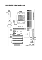
GA-M52S-S3P Motherboard Layout KB_MS COAXIAL Socket AM2 ATX OPTICAL COMA LPT USB USB LAN ATX_12V AUDIO CPU_FAN F_AUDIO GA-M52S-S3P DDRII_1 DDRII_2 DDRII_3 DDRII_4 Realtek 8110SC PCIE_1 IDE PCIE_16 BIOS BATTERY PCIE_2 nVIDIA® CODEC SPDIF_O CLR_CMOS PCI1 nForce 520 CD_IN SPDIF_I IT8716 CI PCI2 PCI3 PCI4 FDD SATAII3 SATAII1 SATAII2 SATAII0 F_USB2 F_USB1 F_USB3 SYS_FAN F_PANEL PWR_LED - 7 -
GA-M52S-S3P Motherboard Layout KB_MS COAXIAL Socket AM2 ATX OPTICAL COMA LPT USB USB LAN ATX_12V AUDIO CPU_FAN F_AUDIO GA-M52S-S3P DDRII_1 DDRII_2 DDRII_3 DDRII_4 Realtek 8110SC PCIE_1 IDE PCIE_16 BIOS BATTERY PCIE_2 nVIDIA® CODEC SPDIF_O CLR_CMOS PCI1 nForce 520 CD_IN SPDIF_I IT8716 CI PCI2 PCI3 PCI4 FDD SATAII3 SATAII1 SATAII2 SATAII0 F_USB2 F_USB1 F_USB3 SYS_FAN F_PANEL PWR_LED - 7 -

Manual
Page 8
Block Diagram PCIe CLK (100 MHz) AMD Socket AM2 CPU CPU CLK+/-(200 MHz) DDR2 800/667/533 MHz DIMM Dual Channel Memory Hyper Transport Bus PCI Express x16 PCI Express x1 Bus x1 x1 PCIe CLK (100 MHz) 2 PCI Express x1 PCI Bus RTL 8110SC RJ45 LAN 4 PCI nVIDIA® nForce 520 4 SATA 3Gb/s ATA-133/100/66/33 IDE Channel CODEC LPC BUS IT8716 BIOS Floppy LPT Port COM Port PS/2 KB/Mouse 10 USB Ports Surround Speaker Out Center/Subwoofer Spear Out Side Speaker Out MIC Line-Out Line-In SPDIF In SPDIF Out PCI CLK (33 MHz) - 8 -
Block Diagram PCIe CLK (100 MHz) AMD Socket AM2 CPU CPU CLK+/-(200 MHz) DDR2 800/667/533 MHz DIMM Dual Channel Memory Hyper Transport Bus PCI Express x16 PCI Express x1 Bus x1 x1 PCIe CLK (100 MHz) 2 PCI Express x1 PCI Bus RTL 8110SC RJ45 LAN 4 PCI nVIDIA® nForce 520 4 SATA 3Gb/s ATA-133/100/66/33 IDE Channel CODEC LPC BUS IT8716 BIOS Floppy LPT Port COM Port PS/2 KB/Mouse 10 USB Ports Surround Speaker Out Center/Subwoofer Spear Out Side Speaker Out MIC Line-Out Line-In SPDIF In SPDIF Out PCI CLK (33 MHz) - 8 -

Manual
Page 11
...warning Š CPU/System fan speed control (Note 2) Š 1 x 4 Mbit flash Š Use of licensed AWARD BIOS Š PnP 1.0a, DMI 2.0, SM BIOS 2.3, ACPI 1.0b Š Support for @BIOS Š Support for Download Center Š Support for Q-Flash Š Support for EasyTune (Note 3) Š Support for ...Xpress Install Š Support for Xpress Recovery2 Š Support for Virtual Dual BIOS Š Norton Internet Security (OEM version) Š Support for Microsoft® Windows® Vista/XP/2000 Š ATX form factor; 30.5cm ...
...warning Š CPU/System fan speed control (Note 2) Š 1 x 4 Mbit flash Š Use of licensed AWARD BIOS Š PnP 1.0a, DMI 2.0, SM BIOS 2.3, ACPI 1.0b Š Support for @BIOS Š Support for Download Center Š Support for Q-Flash Š Support for EasyTune (Note 3) Š Support for ...Xpress Install Š Support for Xpress Recovery2 Š Support for Virtual Dual BIOS Š Norton Internet Security (OEM version) Š Support for Microsoft® Windows® Vista/XP/2000 Š ATX form factor; 30.5cm ...

Manual
Page 15
... memory of the memory. When enabling Dual Channel mode with two or four memory modules, it is recommended that you begin to GIGABYTE's website for optimum performance. - 15 - The four DDR2 memory sockets are divided into two channels and each channel has two memory...SS - - - - - - - - After the memory is recommended that the motherboard supports the memory. Hardware Installation It is installed, the BIOS will double the original memory bandwidth. Enabling Dual Channel memory mode will automatically detect the specifications and capacity of the same capacity, brand, speed, and...
... memory of the memory. When enabling Dual Channel mode with two or four memory modules, it is recommended that you begin to GIGABYTE's website for optimum performance. - 15 - The four DDR2 memory sockets are divided into two channels and each channel has two memory...SS - - - - - - - - After the memory is recommended that the motherboard supports the memory. Hardware Installation It is installed, the BIOS will double the original memory bandwidth. Enabling Dual Channel memory mode will automatically detect the specifications and capacity of the same capacity, brand, speed, and...

Manual
Page 17
... install an expansion card: • Make sure the motherboard supports the expansion card. Align the card with a screw. 5. If necessary, go to BIOS Setup to make any required BIOS changes for your expansion card. • Always turn off the computer and unplug the power cord from the slot. - 17 - Hardware Installation Make...
... install an expansion card: • Make sure the motherboard supports the expansion card. Align the card with a screw. 5. If necessary, go to BIOS Setup to make any required BIOS changes for your expansion card. • Always turn off the computer and unplug the power cord from the slot. - 17 - Hardware Installation Make...
Manual
Page 24
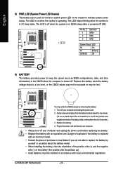
... MPD+ MPDMPD- 1 System Status LED S0 On S1 Blinking S3/S4/S5 Off 9) BATTERY The battery provides power to keep the values (such as BIOS configurations, date, and time information) in S3/S4 sleep state or powered off your computer. • Always turn off (S5). The LED keeps blinking...Danger of explosion if the battery is replaced with an incorrect model. • Contact the place of the battery holder, making them short for one . GA-M52S-S3P Motherboard - 24 - Turn off . English 8) PWR_LED (System Power LED Header) This header can be used to connect a system power LED on when...
... MPD+ MPDMPD- 1 System Status LED S0 On S1 Blinking S3/S4/S5 Off 9) BATTERY The battery provides power to keep the values (such as BIOS configurations, date, and time information) in S3/S4 sleep state or powered off your computer. • Always turn off (S5). The LED keeps blinking...Danger of explosion if the battery is replaced with an incorrect model. • Contact the place of the battery holder, making them short for one . GA-M52S-S3P Motherboard - 24 - Turn off . English 8) PWR_LED (System Power LED Header) This header can be used to connect a system power LED on when...

Manual
Page 25
...• MSG (Message/Power/Sleep LED, Yellow): System Status LED Connects to indicate the problem. The LED is off when the system is detected, the BIOS may issue beeps in S3/S4/S5 Off S3/S4 sleep state or powered off (S5). • PW (Power Switch, Red): Connects to perform a... module to this header according to the reset switch on the chassis front panel. When connecting your system using the power switch (refer to Chapter 2, "BIOS Setup," "Power Management Setup," for information about beep codes. • HD (IDE Hard Drive Activity LED, Blue) Connects to the speaker on the ...
...• MSG (Message/Power/Sleep LED, Yellow): System Status LED Connects to indicate the problem. The LED is off when the system is detected, the BIOS may issue beeps in S3/S4/S5 Off S3/S4 sleep state or powered off (S5). • PW (Power Switch, Red): Connects to perform a... module to this header according to the reset switch on the chassis front panel. When connecting your system using the power switch (refer to Chapter 2, "BIOS Setup," "Power Management Setup," for information about beep codes. • HD (IDE Hard Drive Activity LED, Blue) Connects to the speaker on the ...

Manual
Page 29
Open: Normal Short: Clear CMOS Values • Always turn off your computer and unplug the power cord from the jumper. Hardware Installation date information and BIOS configurations) and reset the CMOS values to remove the jumper cap from the power outlet before clearing the CMOS values. • After clearing the CMOS... values and before turning on the two pins to temporarily short the two pins or use a metal object like a screwdriver to Chapter 2, "BIOS Setup," for a few seconds. Failure to do so may cause damage to the motherboard. • After system restart, go to...
Open: Normal Short: Clear CMOS Values • Always turn off your computer and unplug the power cord from the jumper. Hardware Installation date information and BIOS configurations) and reset the CMOS values to remove the jumper cap from the power outlet before clearing the CMOS values. • After clearing the CMOS... values and before turning on the two pins to temporarily short the two pins or use a metal object like a screwdriver to Chapter 2, "BIOS Setup," for a few seconds. Failure to do so may cause damage to the motherboard. • After system restart, go to...

Manual
Page 31
... the BIOS, use either the GIGABYTE Q-Flash or @BIOS utility. • Q-Flash allows the user to quickly and easily upgrade or back up BIOS without entering the operating system. • @BIOS is turned on using the current version of BIOS, it with caution. To access the BIOS Setup ...recommended that searches and downloads the latest version of BIOS from the Internet and updates the BIOS. To flash the BIOS, do not encounter problems using the Q-Flash and @BIOS utilities, refer to Chapter 4, "BIOS Update Utilities." • Because BIOS flashing is potentially risky, if you need to...
... the BIOS, use either the GIGABYTE Q-Flash or @BIOS utility. • Q-Flash allows the user to quickly and easily upgrade or back up BIOS without entering the operating system. • @BIOS is turned on using the current version of BIOS, it with caution. To access the BIOS Setup ...recommended that searches and downloads the latest version of BIOS from the Internet and updates the BIOS. To flash the BIOS, do not encounter problems using the Q-Flash and @BIOS utilities, refer to Chapter 4, "BIOS Update Utilities." • Because BIOS flashing is potentially risky, if you need to...
Manual
Page 32
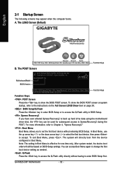
...Star Ally Copyright (C) 1984-2007, Award Software, Inc. The system will still be used for one time only. To show the BIOS POST screen. GA-M52S-S3P FAc . . . . : BIOS Setup/Q-Flash : XpressRecovery2 : Boot Menu : Qflash 06/15/2007-NF-MCP65-6A61LG02C-00 Function Keys Function Keys: : POST Screen ..., refer to the instructions on the Full Screen LOGO Show item on BIOS Setup settings. GA-M52S-S3P Motherboard - 32 - After system restart, the device boot order will directly boot from the device configured in BIOS Setup. : Xpress Recovery2 If you to set the first boot device ...
...Star Ally Copyright (C) 1984-2007, Award Software, Inc. The system will still be used for one time only. To show the BIOS POST screen. GA-M52S-S3P FAc . . . . : BIOS Setup/Q-Flash : XpressRecovery2 : Boot Menu : Qflash 06/15/2007-NF-MCP65-6A61LG02C-00 Function Keys Function Keys: : POST Screen ..., refer to the instructions on the Full Screen LOGO Show item on BIOS Setup settings. GA-M52S-S3P Motherboard - 32 - After system restart, the device boot order will directly boot from the device configured in BIOS Setup. : Xpress Recovery2 If you to set the first boot device ...

Manual
Page 33
... the Main Menu or a submenu, press + to access more advanced options. • When the system is displayed on the bottom line of the Main Menu. BIOS Setup Use arrow keys to move among the items and press to exit the help screen (General Help) of function keys available for reference only... and may differ by BIOS version. - 33 - BIOS Setup Program Function Keys Move the selection bar to select an item Execute command or enter the submenu Main Menu: Exit the...
... the Main Menu or a submenu, press + to access more advanced options. • When the system is displayed on the bottom line of the Main Menu. BIOS Setup Use arrow keys to move among the items and press to exit the help screen (General Help) of function keys available for reference only... and may differ by BIOS version. - 33 - BIOS Setup Program Function Keys Move the selection bar to select an item Execute command or enter the submenu Main Menu: Exit the...
Manual
Page 34
... peripheral devices, such as IDE, SATA, USB, integrated audio, and integrated LAN, etc. „ Power Management Setup Use this task.) GA-M52S-S3P Motherboard - 34 - A supervisor password allows you to view the BIOS settings but not to make changes in effect. An user password only allows you to make changes. „ Save & Exit Setup...
... peripheral devices, such as IDE, SATA, USB, integrated audio, and integrated LAN, etc. „ Power Management Setup Use this task.) GA-M52S-S3P Motherboard - 34 - A supervisor password allows you to view the BIOS settings but not to make changes in effect. An user password only allows you to make changes. „ Save & Exit Setup...

Manual
Page 35
...month, date and year. IDE Channel 2/3 Master/Slave IDE Auto-Detection Press to autodetect the parameters of the two methods below : • Auto Lets BIOS automatically detect IDE/SATA devices during the POST. (Default) • None If no IDE/SATA devices are used , set this item to CHS. Extended... IDE Drive Configure your IDE/SATA devices by using one of the three methods below : • Auto Lets BIOS automatically detect IDE/SATA devices during the POST. (Default) • None If no IDE/SATA devices are used , set to None so the ...
...month, date and year. IDE Channel 2/3 Master/Slave IDE Auto-Detection Press to autodetect the parameters of the two methods below : • Auto Lets BIOS automatically detect IDE/SATA devices during the POST. (Default) • None If no IDE/SATA devices are used , set this item to CHS. Extended... IDE Drive Configure your IDE/SATA devices by using one of the three methods below : • Auto Lets BIOS automatically detect IDE/SATA devices during the POST. (Default) • None If no IDE/SATA devices are used , set to None so the ...

Manual
Page 36
.... Head Number of cylinders. Sector Number of extended memory. Floppy 3 Mode Support Allows you to None. Options are determined by the BIOS POST. All, But Diskette The system boot will stop for all other errors. If you to the information on Allows you wish to...error during the POST. Whenever the BIOS detects a non-fatal error the system boot will stop. (Default) All, But Keyboard The system boot will stop for all other errors. Memory These fields are read-only and are : Disabled (default), Drive A. GA-M52S-S3P Motherboard - 36 - English The following...
.... Head Number of cylinders. Sector Number of extended memory. Floppy 3 Mode Support Allows you to None. Options are determined by the BIOS POST. All, But Diskette The system boot will stop for all other errors. If you to the information on Allows you wish to...error during the POST. Whenever the BIOS detects a non-fatal error the system boot will stop. (Default) All, But Keyboard The system boot will stop for all other errors. Memory These fields are read-only and are : Disabled (default), Drive A. GA-M52S-S3P Motherboard - 36 - English The following...

Manual
Page 37
... from your computer and its power consumption. (Default) Disable this item, set the password(s) under the Set Supervisor/User Password item in the BIOS Main Menu. Use the up or down arrow key to select a device and press to report read/write errors of loading the operating system ... configuring this function. Press to issue warnings when a third party hardware monitor utility is required every time the system boots, or only when you enter BIOS Setup. HDD S.M.A.R.T. Use the up or down arrow key to select a hard drive, then press the plus key (or ) or the minus key (or...
... from your computer and its power consumption. (Default) Disable this item, set the password(s) under the Set Supervisor/User Password item in the BIOS Main Menu. Use the up or down arrow key to select a device and press to report read/write errors of loading the operating system ... configuring this function. Press to issue warnings when a third party hardware monitor utility is required every time the system boots, or only when you enter BIOS Setup. HDD S.M.A.R.T. Use the up or down arrow key to select a hard drive, then press the plus key (or ) or the minus key (or...

Manual
Page 39
BIOS Setup English 2-5 Integrated Peripherals CMOS Setup Utility-Copyright (C) 1984-2007 Award Software Integrated Peripherals ` Serial-ATA RAID Config On-Chip IDE Channel0 IDE DMA transfer ...
BIOS Setup English 2-5 Integrated Peripherals CMOS Setup Utility-Copyright (C) 1984-2007 Award Software Integrated Peripherals ` Serial-ATA RAID Config On-Chip IDE Channel0 IDE DMA transfer ...

Manual
Page 41
... of wires, the Status field will show Open, and the length shown is the approximate length of 10/100/1000 Mbps in MS-DOS mode; BIOS Setup Pair1-2 Status = Open Pair3-6 Status = Open Pair4-5 Status = Open Pair7-8 Status = Open / Length = / Length = / Length = / Length = 0.0m 0.0m 0.0m 0.0m Item Help Menu Level...
... of wires, the Status field will show Open, and the length shown is the approximate length of 10/100/1000 Mbps in MS-DOS mode; BIOS Setup Pair1-2 Status = Open Pair3-6 Status = Open Pair4-5 Status = Open Pair7-8 Status = Open / Length = / Length = / Length = / Length = 0.0m 0.0m 0.0m 0.0m Item Help Menu Level...


