Manual
Page 3
...CO., LTD. All rights reserved. No part of this manual is protected by copyright laws and is 1.0. Disclaimer Information in the use GIGABYTE's unique features, read the User's Manual. For instructions on how to use of the motherboard is the property of the ...the Support\Motherboard\Technology Guide page on your motherboard revision before updating motherboard BIOS, drivers, or when looking for technical information. For product-related information, check on our website at: http://www.gigabyte.com.tw Identifying Your Motherboard Revision The revision number on our website....
...CO., LTD. All rights reserved. No part of this manual is protected by copyright laws and is 1.0. Disclaimer Information in the use GIGABYTE's unique features, read the User's Manual. For instructions on how to use of the motherboard is the property of the ...the Support\Motherboard\Technology Guide page on your motherboard revision before updating motherboard BIOS, drivers, or when looking for technical information. For product-related information, check on our website at: http://www.gigabyte.com.tw Identifying Your Motherboard Revision The revision number on our website....
Manual
Page 4
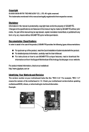
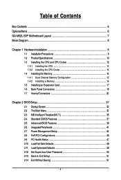
Table of Contents Box Contents ...6 OptionalItems...6 GA-M52L-S3P Motherboard Layout 7 Block Diagram...8 Chapter 1 Hardware Installation 9 1-1 Installation Precautions 9 1-2 Product Specifications 10 1-3 Installing the CPU and CPU Cooler ... Installing an Expansion Card 17 1-6 Back Panel Connectors 18 1-7 Internal Connectors 20 Chapter 2 BIOS Setup 31 2-1 Startup Screen 32 2-2 The Main Menu 33 2-3 MB Intelligent Tweaker(M.I.T 35 2-4 Standard CMOS Features 37 2-5 Advanced BIOS Features 39 2-6 IntegratedPeripherals 41 2-7 Power Management Setup 44 2-8 PnP/PCI Configurations 46 2-9 ...
Table of Contents Box Contents ...6 OptionalItems...6 GA-M52L-S3P Motherboard Layout 7 Block Diagram...8 Chapter 1 Hardware Installation 9 1-1 Installation Precautions 9 1-2 Product Specifications 10 1-3 Installing the CPU and CPU Cooler ... Installing an Expansion Card 17 1-6 Back Panel Connectors 18 1-7 Internal Connectors 20 Chapter 2 BIOS Setup 31 2-1 Startup Screen 32 2-2 The Main Menu 33 2-3 MB Intelligent Tweaker(M.I.T 35 2-4 Standard CMOS Features 37 2-5 Advanced BIOS Features 39 2-6 IntegratedPeripherals 41 2-7 Power Management Setup 44 2-8 PnP/PCI Configurations 46 2-9 ...

Manual
Page 5
... 54 3-3 Technical Manuals 54 3-4 Contact ...55 3-5 System ...55 3-6 Download Center 56 Chapter 4 Unique Features 57 4-1 Xpress Recovery2 57 4-2 BIOS Update Utilities 60 4-2-1 Updating the BIOS with the Q-Flash Utility 60 4-2-2 Updating the BIOS with the @BIOS Utility 63 4-3 EasyTune 5 ...65 Chapter 5 Appendix ...67 5-1 Configuring SATA Hard Drive(s 67 5-1-1 Configuring the Onboard SATA Controller 67...
... 54 3-3 Technical Manuals 54 3-4 Contact ...55 3-5 System ...55 3-6 Download Center 56 Chapter 4 Unique Features 57 4-1 Xpress Recovery2 57 4-2 BIOS Update Utilities 60 4-2-1 Updating the BIOS with the Q-Flash Utility 60 4-2-2 Updating the BIOS with the @BIOS Utility 63 4-3 EasyTune 5 ...65 Chapter 5 Appendix ...67 5-1 Configuring SATA Hard Drive(s 67 5-1-1 Configuring the Onboard SATA Controller 67...
Manual
Page 8
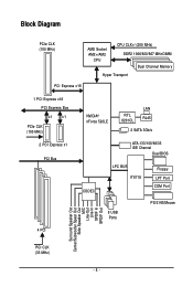
Block Diagram PCIe CLK (100 MHz) AMD Socket AM2+/AM2 CPU CPU CLK+/-(200 MHz) DDR2 1066/800/667 MHz DIMM Dual Channel Memory Hyper Transport PCI Express x16 1 PCI Express x16 PCI Express Bus x1 x1 PCIe CLK (100 MHz) 2 PCI Express x1 PCI Bus 4 PCI NVIDIA® nForce 520LE RTL 8201CL LAN RJ45 2 SATA 3Gb/s ATA-133/100/66/33 IDE Channel Dual BIOS CODEC LPC BUS IT8718 Floppy LPT Port COM Port 8 USB Ports PS/2 KB/Mouse Surround Speaker Out Center/Subwoofer Spear Out Side Speaker Out MIC Line-Out Line-In SPDIF In SPDIF Out PCI CLK (33 MHz) - 8 -
Block Diagram PCIe CLK (100 MHz) AMD Socket AM2+/AM2 CPU CPU CLK+/-(200 MHz) DDR2 1066/800/667 MHz DIMM Dual Channel Memory Hyper Transport PCI Express x16 1 PCI Express x16 PCI Express Bus x1 x1 PCIe CLK (100 MHz) 2 PCI Express x1 PCI Bus 4 PCI NVIDIA® nForce 520LE RTL 8201CL LAN RJ45 2 SATA 3Gb/s ATA-133/100/66/33 IDE Channel Dual BIOS CODEC LPC BUS IT8718 Floppy LPT Port COM Port 8 USB Ports PS/2 KB/Mouse Surround Speaker Out Center/Subwoofer Spear Out Side Speaker Out MIC Line-Out Line-In SPDIF In SPDIF Out PCI CLK (33 MHz) - 8 -
Manual
Page 11
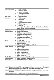
... warning CPU/System fan speed control (Note 2) BIOS 2 x 8 Mbit flash Use of licensed AWARD BIOS Support for DualBIOSTM PnP 1.0a, DMI 2.0, SM BIOS 2.4, ACPI 1.0b Unique Features Support for @BIOS Support for Q-Flash Support for Virtual Dual BIOS Support for Download Center Support for Xpress...
... warning CPU/System fan speed control (Note 2) BIOS 2 x 8 Mbit flash Use of licensed AWARD BIOS Support for DualBIOSTM PnP 1.0a, DMI 2.0, SM BIOS 2.4, ACPI 1.0b Unique Features Support for @BIOS Support for Q-Flash Support for Virtual Dual BIOS Support for Download Center Support for Xpress...
Manual
Page 15
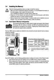
... the same capacity, brand, speed, and chips be installed in the DDR2_1 and DDR2_2 sockets. Dual Channel mode cannot be installed, it is installed, the BIOS will double the original memory bandwidth. DS/SS DS/SS Four Modules DS/SS DS/SS DS/SS DS/SS (SS=Single-Sided, DS=Double...-Sided, "- -"=No Memory) If two memory modules are to GIGABYTE's website for optimum performance. - 15 - It is recommended that you install them in only one DDR2 memory module is recommended that memory of the same...
... the same capacity, brand, speed, and chips be installed in the DDR2_1 and DDR2_2 sockets. Dual Channel mode cannot be installed, it is installed, the BIOS will double the original memory bandwidth. DS/SS DS/SS Four Modules DS/SS DS/SS DS/SS DS/SS (SS=Single-Sided, DS=Double...-Sided, "- -"=No Memory) If two memory modules are to GIGABYTE's website for optimum performance. - 15 - It is recommended that you install them in only one DDR2 memory module is recommended that memory of the same...

Manual
Page 17
...PCI Express x1 slot PCI Express x16 slot PCI slot Follow the steps below to correctly install your expansion card(s). 7. If necessary, go to BIOS Setup to prevent hardware damage. Example: Installing and Removing a PCI Express x16 Graphics Card: • Installing a Graphics Card: Gently push down ... back panel with a screw. 5. 1-5 Installing an Expansion Card Read the following guidelines before installing an expansion card to make any required BIOS changes for your expansion card in your computer. Secure the card's metal bracket to install an expansion card: • Make sure the ...
...PCI Express x1 slot PCI Express x16 slot PCI slot Follow the steps below to correctly install your expansion card(s). 7. If necessary, go to BIOS Setup to prevent hardware damage. Example: Installing and Removing a PCI Express x16 Graphics Card: • Installing a Graphics Card: Gently push down ... back panel with a screw. 5. 1-5 Installing an Expansion Card Read the following guidelines before installing an expansion card to make any required BIOS changes for your expansion card in your computer. Secure the card's metal bracket to install an expansion card: • Make sure the ...
Manual
Page 24
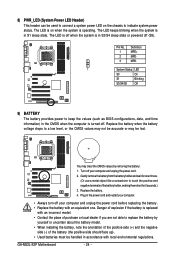
... like a screwdriver to touch the positive and negative terminals of purchase or local dealer if you are not able to keep the values (such as BIOS configurations, date, and time information) in the CMOS when the computer is turned off (S5). 8) PWR_LED (System Power LED Header) This header can ...sleep state. You may be handled in accordance with an incorrect model. • Contact the place of the battery holder, making them short for one . GA-M52L-S3P Motherboard - 24 - The LED is on the chassis to a low level, or the CMOS values may not be accurate or may clear the CMOS ...
... like a screwdriver to touch the positive and negative terminals of purchase or local dealer if you are not able to keep the values (such as BIOS configurations, date, and time information) in the CMOS when the computer is turned off (S5). 8) PWR_LED (System Power LED Header) This header can ...sleep state. You may be handled in accordance with an incorrect model. • Contact the place of the battery holder, making them short for one . GA-M52L-S3P Motherboard - 24 - The LED is on the chassis to a low level, or the CMOS values may not be accurate or may clear the CMOS ...

Manual
Page 25
PW+ PWSPEAK+ SPEAK- 2 20 1 19 HD+ HD- When connecting your system using the power switch (refer to Chapter 2, "BIOS Setup," "Power Management Setup," for information about beep codes. • HD (IDE Hard Drive Activity LED, Blue) Connects to the hard drive activity LED... on the chassis front panel. The S0 On LED is detected, the BIOS may differ by issuing a beep code. Hardware Installation If a problem is on the chassis front panel. 10) F_PANEL (Front Panel Header) Connect the ...
PW+ PWSPEAK+ SPEAK- 2 20 1 19 HD+ HD- When connecting your system using the power switch (refer to Chapter 2, "BIOS Setup," "Power Management Setup," for information about beep codes. • HD (IDE Hard Drive Activity LED, Blue) Connects to the hard drive activity LED... on the chassis front panel. The S0 On LED is detected, the BIOS may differ by issuing a beep code. Hardware Installation If a problem is on the chassis front panel. 10) F_PANEL (Front Panel Header) Connect the ...
Manual
Page 29
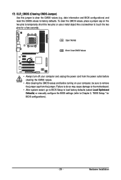
...do so may cause damage to the motherboard. • After system restart, go to BIOS Setup to load factory defaults (select Load Optimized Defaults) or manually configure the BIOS settings (refer to touch the two pins for BIOS configurations). - 29 - Open: Normal Short: Clear CMOS Values • Always turn ...values and before turning on the two pins to temporarily short the two pins or use a metal object like a screwdriver to Chapter 2, "BIOS Setup," for a few seconds. Hardware Installation 17) CLR_CMOS (Clearing CMOS Jumper) Use this jumper to factory defaults. date information and...
...do so may cause damage to the motherboard. • After system restart, go to BIOS Setup to load factory defaults (select Load Optimized Defaults) or manually configure the BIOS settings (refer to touch the two pins for BIOS configurations). - 29 - Open: Normal Short: Clear CMOS Values • Always turn ...values and before turning on the two pins to temporarily short the two pins or use a metal object like a screwdriver to Chapter 2, "BIOS Setup," for a few seconds. Hardware Installation 17) CLR_CMOS (Clearing CMOS Jumper) Use this jumper to factory defaults. date information and...

Manual
Page 31
... or to activate certain system features. Refer to Chapter 5, "Troubleshooting," for how to prevent system instability or other unexpected results. To upgrade the BIOS, use either the GIGABYTE Q-Flash or @BIOS utility. • Q-Flash allows the user to keep the configuration values in the CMOS on . When the power is turned off, the...
... or to activate certain system features. Refer to Chapter 5, "Troubleshooting," for how to prevent system instability or other unexpected results. To upgrade the BIOS, use either the GIGABYTE Q-Flash or @BIOS utility. • Q-Flash allows the user to keep the configuration values in the CMOS on . When the power is turned off, the...

Manual
Page 32
... device, then press to set the first boot device without having to XpressRecovery2 during the POST. To exit Boot Menu, press . The LOGO Screen (Default) B. GA-M52L-S3P Motherboard - 32 - A. To show the BIOS POST screen. Note: The setting in Boot Menu is effective for subsequent access to enter...
... device, then press to set the first boot device without having to XpressRecovery2 during the POST. To exit Boot Menu, press . The LOGO Screen (Default) B. GA-M52L-S3P Motherboard - 32 - A. To show the BIOS POST screen. Note: The setting in Boot Menu is effective for subsequent access to enter...
Manual
Page 33
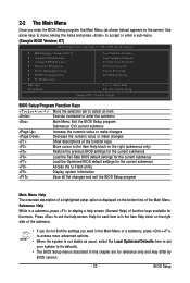
...not stable as shown below) appears on the bottom line of the Main Menu. Submenu Help While in a submenu, press to display a help screen. BIOS Setup Help for each item is displayed on the screen. Press to the Item Help block on the right (submenus only) Restore the previous... right side of function keys available for the current submenus Access the Q-Flash utility Display system information Save all the changes and exit the BIOS Setup program Main Menu Help The onscreen description of a highlighted setup option is in this chapter are for reference only and may differ by...
...not stable as shown below) appears on the bottom line of the Main Menu. Submenu Help While in a submenu, press to display a help screen. BIOS Setup Help for each item is displayed on the screen. Press to the Item Help block on the right (submenus only) Restore the previous... right side of function keys available for the current submenus Access the Q-Flash utility Display system information Save all the changes and exit the BIOS Setup program Main Menu Help The onscreen description of a highlighted setup option is in this chapter are for reference only and may differ by...
Manual
Page 34
... to make changes. Save & Exit Setup Save all the changes made in the BIOS Setup program to the confirmation message will exit BIOS Setup. (Pressing can also carry out this task.) GA-M52L-S3P Motherboard - 34 - MB Intelligent Tweaker(M.I.T.) Use this menu to configure the clock,...Configurations Use this menu to configure the system's PCI & PnP resources. PC Health Status Use this menu to the system and BIOS Setup. An user password only allows you to restrict access to see information about autodetected system/CPU temperature, system voltage and fan speed, etc...
... to make changes. Save & Exit Setup Save all the changes made in the BIOS Setup program to the confirmation message will exit BIOS Setup. (Pressing can also carry out this task.) GA-M52L-S3P Motherboard - 34 - MB Intelligent Tweaker(M.I.T.) Use this menu to configure the clock,...Configurations Use this menu to configure the system's PCI & PnP resources. PC Health Status Use this menu to the system and BIOS Setup. An user password only allows you to restrict access to see information about autodetected system/CPU temperature, system voltage and fan speed, etc...

Manual
Page 35
... CPU. (Note) This item is dependent on the CPU being used . (Default: Auto) CPU NorthBridge Freq. (Note) Allows you to set the PCIe clock frequency. BIOS Setup PCIE Clock (MHz) Allows you to CPU, chipset, or memory and reduce the useful life of these components.
... CPU. (Note) This item is dependent on the CPU being used . (Default: Auto) CPU NorthBridge Freq. (Note) Allows you to set the PCIe clock frequency. BIOS Setup PCIE Clock (MHz) Allows you to CPU, chipset, or memory and reduce the useful life of these components.
Manual
Page 37
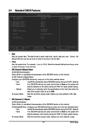
... is 13:0:0. Extended IDE Drive Configure your IDE/SATA devices by using one of the two methods below : • Auto • None Lets BIOS automatically detect IDE/SATA devices during the POST for faster system startup. Time Sets the system time. is week (read-only), month, date and year... drive when the hard drive access mode is set to set this channel. Access Mode Sets the hard drive access mode. For example, 1 p.m. BIOS Setup IDE Channel 0 Master/Slave Configure your IDE/SATA devices by using one of the three methods below : • Auto Lets...
... is 13:0:0. Extended IDE Drive Configure your IDE/SATA devices by using one of the two methods below : • Auto • None Lets BIOS automatically detect IDE/SATA devices during the POST for faster system startup. Time Sets the system time. is week (read-only), month, date and year... drive when the hard drive access mode is set to set this channel. Access Mode Sets the hard drive access mode. For example, 1 p.m. BIOS Setup IDE Channel 0 Master/Slave Configure your IDE/SATA devices by using one of the three methods below : • Auto Lets...

Manual
Page 38
... drive. Base Memory Also called conventional memory. Memory These fields are read-only and are determined by the BIOS POST. GA-M52L-S3P Motherboard - 38 - Precomp Write precompensation cylinder. Landing Zone Landing zone. All Errors Whenever the BIOS detects a non-fatal error the system boot will not stop for a keyboard or a floppy disk drive error...
... drive. Base Memory Also called conventional memory. Memory These fields are read-only and are determined by the BIOS POST. GA-M52L-S3P Motherboard - 38 - Precomp Write precompensation cylinder. Landing Zone Landing zone. All Errors Whenever the BIOS detects a non-fatal error the system boot will not stop for a keyboard or a floppy disk drive error...
Manual
Page 39
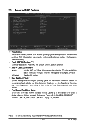
... down arrow key to select a device and press to exit this feature. - 39 - 2-5 Advanced BIOS Features CMOS Setup Utility-Copyright (C) 1984-2008 Award Software Advanced BIOS Features Virtualization Patch AMD TLB Erratum (Note) AMD K8 Cool&Quiet control Hard Disk Boot Priority...Virtualization Virtualization allows a platform to reduce heat output from your computer and its power consumption. (Default) Disabled Disables this function. BIOS Setup Hard Disk Boot Priority Specifies the sequence of loading the operating system from the available devices. Use the up or down ...
... down arrow key to select a device and press to exit this feature. - 39 - 2-5 Advanced BIOS Features CMOS Setup Utility-Copyright (C) 1984-2008 Award Software Advanced BIOS Features Virtualization Patch AMD TLB Erratum (Note) AMD K8 Cool&Quiet control Hard Disk Boot Priority...Virtualization Virtualization allows a platform to reduce heat output from your computer and its power consumption. (Default) Disabled Disables this function. BIOS Setup Hard Disk Boot Priority Specifies the sequence of loading the operating system from the available devices. Use the up or down ...
Manual
Page 40
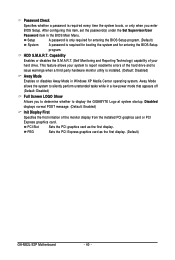
... Display First Specifies the first initiation of your system to report read/write errors of the hard drive and to display the GIGABYTE Logo at system startup. This feature allows your hard drive. Password Check Specifies whether a password is required every time the ... password is installed. (Default: Disabled) Away Mode Enables or disables Away Mode in the BIOS Main Menu. HDD S.M.A.R.T. PCI Slot Sets the PCI graphics card as the first display. (Default) GA-M52L-S3P Motherboard - 40 - Away Mode allows the system to silently perform unattended tasks while in a...
... Display First Specifies the first initiation of your system to report read/write errors of the hard drive and to display the GIGABYTE Logo at system startup. This feature allows your hard drive. Password Check Specifies whether a password is required every time the ... password is installed. (Default: Disabled) Away Mode Enables or disables Away Mode in the BIOS Main Menu. HDD S.M.A.R.T. PCI Slot Sets the PCI graphics card as the first display. (Default) GA-M52L-S3P Motherboard - 40 - Away Mode allows the system to silently perform unattended tasks while in a...
Manual
Page 41
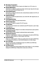
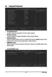
...: Enabled) NV SATA Controller Enables or disables the integrated SATA 3Gb/s controller. (Default: Enabled) IDE Prefetch Mode Enables or disbales prefetch mode for USB devices. BIOS Setup Enabled activates the IDE prefetch buffer to enhance hard drive performance. (Default: Enabled) USB Memory Type Specifies the type of memory allocated for the...
...: Enabled) NV SATA Controller Enables or disables the integrated SATA 3Gb/s controller. (Default: Enabled) IDE Prefetch Mode Enables or disbales prefetch mode for USB devices. BIOS Setup Enabled activates the IDE prefetch buffer to enhance hard drive performance. (Default: Enabled) USB Memory Type Specifies the type of memory allocated for the...


