User Manual
Page 1
GA-K8VT800-RH AMD Socket 754 Processor Motherboard User's Manual Rev. 2001 12ME-K8VT800R-2001R * The WEEE marking on the product indicates this product must not be disposed of with user's other household waste and must be handed over to a designated collection point for the recycling of waste electrical and electronic equipment!! * The WEEE marking applies only in European Union's member states.
GA-K8VT800-RH AMD Socket 754 Processor Motherboard User's Manual Rev. 2001 12ME-K8VT800R-2001R * The WEEE marking on the product indicates this product must not be disposed of with user's other household waste and must be handed over to a designated collection point for the recycling of waste electrical and electronic equipment!! * The WEEE marking applies only in European Union's member states.

User Manual
Page 2
Motherboard GA-K8VT800-RH JUNE. 21, 2006 Motherboard GA-K8VT800-RH June. 21, 2006
Motherboard GA-K8VT800-RH JUNE. 21, 2006 Motherboard GA-K8VT800-RH June. 21, 2006
User Manual
Page 4
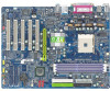
Table of Contents ItemChecklist ...6 OptionalAccessories ...6 GA-K8VT800-RH Motherboard Layout 7 Block Diagram ...8 Chapter 1 Hardware Installation 9 1-1 Considerations Prior to Installation 9 1-2 Feature Summary 10 1-3 Installation of the CPU and Heatsink 12 1-3-1 Installation of the CPU 12 1-3-2 ...
Table of Contents ItemChecklist ...6 OptionalAccessories ...6 GA-K8VT800-RH Motherboard Layout 7 Block Diagram ...8 Chapter 1 Hardware Installation 9 1-1 Considerations Prior to Installation 9 1-2 Feature Summary 10 1-3 Installation of the CPU and Heatsink 12 1-3-1 Installation of the CPU 12 1-3-2 ...

User Manual
Page 9
... computer power during the installation process can become damaged as a result of the motherboard or any metal leads or connectors. 3. Damage due to be an unofficial Gigabyte product. - 9 - Hardware Installation English Chapter 1 Hardware Installation 1-1 Considerations Prior... to Installation Preparing Your Computer The motherboard contains numerous delicate electronic circuits and components which can lead to...
... computer power during the installation process can become damaged as a result of the motherboard or any metal leads or connectors. 3. Damage due to be an unofficial Gigabyte product. - 9 - Hardware Installation English Chapter 1 Hardware Installation 1-1 Considerations Prior... to Installation Preparing Your Computer The motherboard contains numerous delicate electronic circuits and components which can lead to...
User Manual
Page 10
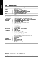
GA-K8VT800-RH Motherboard - 10 - English 1-2 Feature Summary CPU Chipset Memory Slots IDE Connections FDD Connections Onboard SATA Peripherals Onboard LAN Onboard Audio I/O Control Hardware Monitor Š Socket 754 ...
GA-K8VT800-RH Motherboard - 10 - English 1-2 Feature Summary CPU Chipset Memory Slots IDE Connections FDD Connections Onboard SATA Peripherals Onboard LAN Onboard Audio I/O Control Hardware Monitor Š Socket 754 ...
User Manual
Page 12
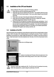
... the processor. Please add an even layer of the CPU. If you install the CPU in Figure 1.(90o to the plane of the motherboard) prior to the locked position while holding pressure on the Socket and Processor. Do not force the processor into place. Fig.2 Pin 1...system use, otherwise overheating and permanent damage of the CPU may occur. 5. Align the processor to set the CPU host frequency in Figure 2. GA-K8VT800-RH Motherboard - 12 - English 1-3 Installation of the CPU and Heatsink Before installing the CPU, please comply with the processor specifications. Please make sure the...
... the processor. Please add an even layer of the CPU. If you install the CPU in Figure 1.(90o to the plane of the motherboard) prior to the locked position while holding pressure on the Socket and Processor. Do not force the processor into place. Fig.2 Pin 1...system use, otherwise overheating and permanent damage of the CPU may occur. 5. Align the processor to set the CPU host frequency in Figure 2. GA-K8VT800-RH Motherboard - 12 - English 1-3 Installation of the CPU and Heatsink Before installing the CPU, please comply with the processor specifications. Please make sure the...
User Manual
Page 13
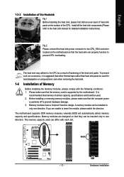
...sink may adhere to the CPU as a result of hardening of Memory Before installing the memory modules, please comply with each slot. The motherboard supports DDR memory modules, whereby BIOS will automatically detect memory capacity and specifications. If you are designed so that they can be installed ... 1-3-2 Installation of the Heatsink Fig.1 Before installing the heat sink, please first add an even layer of heat sink paste on the motherboard so that the heat sink can properly function to prevent CPU overheating. Install all the heat sink components (Please refer to the heat sink...
...sink may adhere to the CPU as a result of hardening of Memory Before installing the memory modules, please comply with each slot. The motherboard supports DDR memory modules, whereby BIOS will automatically detect memory capacity and specifications. If you are designed so that they can be installed ... 1-3-2 Installation of the Heatsink Fig.1 Before installing the heat sink, please first add an even layer of heat sink paste on the motherboard so that the heat sink can properly function to prevent CPU overheating. Install all the heat sink components (Please refer to the heat sink...
User Manual
Page 14
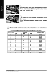
... 400 DDR 400 DDR 400 DDR 400 DDR 400 DDR 400 DDR 400 DDR 400 DDR 400 DDR 333 DDR 400 DDR 400 DDR 333 GA-K8VT800-RH Motherboard - 14 - English Fig.1 The DIMM socket has a notch, so the DIMM memory module can only fit in one direction.
... 400 DDR 400 DDR 400 DDR 400 DDR 400 DDR 400 DDR 400 DDR 400 DDR 400 DDR 333 DDR 400 DDR 400 DDR 333 GA-K8VT800-RH Motherboard - 14 - English Fig.1 The DIMM socket has a notch, so the DIMM memory module can only fit in one direction.
User Manual
Page 15
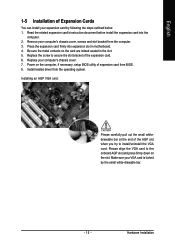
... Expansion Cards You can install your computer's chassis cover. 7. Press the expansion card firmly into the computer. 2. Power on the card are indeed seated in motherboard. 4. Please align the VGA card to install/uninstall the VGA card. Hardware Installation Replace the screw to secure the slot bracket of expansion card from...
... Expansion Cards You can install your computer's chassis cover. 7. Press the expansion card firmly into the computer. 2. Power on the card are indeed seated in motherboard. 4. Please align the VGA card to install/uninstall the VGA card. Hardware Installation Replace the screw to secure the slot bracket of expansion card from...
User Manual
Page 16
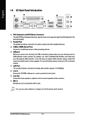
.../2 Mouse Connector To install a PS/2 port keyboard and mouse, plug the mouse to the upper port (green) and the keyboard to configure 2-/4-/6-/8-channel audio function. GA-K8VT800-RH Motherboard - 16 - Parallel Port The parallel port allows connection of 10/100Mbps.
.../2 Mouse Connector To install a PS/2 port keyboard and mouse, plug the mouse to the upper port (green) and the keyboard to configure 2-/4-/6-/8-channel audio function. GA-K8VT800-RH Motherboard - 16 - Parallel Port The parallel port allows connection of 10/100Mbps.
User Manual
Page 18
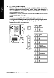
... are properly installed. Align the power connector with its proper location on /off) 15 GND 16 GND 17 GND 18 -5V 19 +5V 20 +5V GA-K8VT800-RH Motherboard - 18 - The ATX_12V power connector mainly supplies power to handle the system voltage requirements. Definition 11 1 1 3.3V 2 3.3V 3 GND 4 +5V...GND 8 Power Good 9 5V SB (stand by +5V) 20 10 10 +12V 11 3.3V 12 -12V 13 GND 14 PS_ON(soft on the motherboard and connect tightly. If a power supply is able to the CPU. If the ATX_12V power connector is unable to start . English 1/2) ATX_12V / ...
... are properly installed. Align the power connector with its proper location on /off) 15 GND 16 GND 17 GND 18 -5V 19 +5V 20 +5V GA-K8VT800-RH Motherboard - 18 - The ATX_12V power connector mainly supplies power to handle the system voltage requirements. Definition 11 1 1 3.3V 2 3.3V 3 GND 4 +5V...GND 8 Power Good 9 5V SB (stand by +5V) 20 10 10 +12V 11 3.3V 12 -12V 13 GND 14 PS_ON(soft on the motherboard and connect tightly. If a power supply is able to the CPU. If the ATX_12V power connector is unable to start . English 1/2) ATX_12V / ...

User Manual
Page 20
... connects to the FDD drive. Before attaching the FDD cable, please take note of the foolproof groove in the IDE connector. 39 1 IDE1 IDE2 40 2 GA-K8VT800-RH Motherboard - 20 - English 5) FDD (FDD Connector) The FDD connector is used to connect the FDD cable while the other as Slave (for information on settings...
... connects to the FDD drive. Before attaching the FDD cable, please take note of the foolproof groove in the IDE connector. 39 1 IDE1 IDE2 40 2 GA-K8VT800-RH Motherboard - 20 - English 5) FDD (FDD Connector) The FDD connector is used to connect the FDD cable while the other as Slave (for information on settings...
User Manual
Page 22
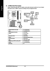
... NC RST- Pin 3: NC Pin 4: Data(-) Open: Normal Close: Reset Hardware System Open: Normal Close: Power On/Off Pin 1: LED anode(+) Pin 2: LED cathode(-) NC GA-K8VT800-RH Motherboard - 22 - RST+ Reset Switch HD (IDE Hard Disk Active LED) (Blue) SPEAK (Speaker Connector) (Amber) RES (Reset Switch) (Green) PW (Power Switch) (Red) MSG...
... NC RST- Pin 3: NC Pin 4: Data(-) Open: Normal Close: Reset Hardware System Open: Normal Close: Power On/Off Pin 1: LED anode(+) Pin 2: LED cathode(-) NC GA-K8VT800-RH Motherboard - 22 - RST+ Reset Switch HD (IDE Hard Disk Active LED) (Blue) SPEAK (Speaker Connector) (Amber) RES (Reset Switch) (Green) PW (Power Switch) (Red) MSG...

User Manual
Page 24
... feature only when your nearest dealer for optional SUR_CEN cable. 2 8 1 7 Pin No. 1 2 3 4 5 6 7 8 Definition SUR OUTL SUR OUTR GND No Pin CENTER_OUT BASS_OUT AUX_L AUX_R GA-K8VT800-RH Motherboard - 24 - For optional SPDIF cable, please contact your local dealer. 26 15 Pin No. 1 2 3 4 5 6 Definition Power No Pin SPDIF SPDIFI GND GND 13) SUR_CEN (Surround...
... feature only when your nearest dealer for optional SUR_CEN cable. 2 8 1 7 Pin No. 1 2 3 4 5 6 7 8 Definition SUR OUTL SUR OUTR GND No Pin CENTER_OUT BASS_OUT AUX_L AUX_R GA-K8VT800-RH Motherboard - 24 - For optional SPDIF cable, please contact your local dealer. 26 15 Pin No. 1 2 3 4 5 6 Definition Power No Pin SPDIF SPDIFI GND GND 13) SUR_CEN (Surround...
User Manual
Page 26
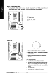
To clear CMOS, temporarily short 1-2 pin. Open: Normal 1 Short: Clear CMOS 1 17) BATTERY GA-K8VT800-RH Motherboard Danger of used batteries according to prevent from improper use a metal object to connect the positive and negative pins in and turn on the computer. - ...
To clear CMOS, temporarily short 1-2 pin. Open: Normal 1 Short: Clear CMOS 1 17) BATTERY GA-K8VT800-RH Motherboard Danger of used batteries according to prevent from improper use a metal object to connect the positive and negative pins in and turn on the computer. - ...
User Manual
Page 29
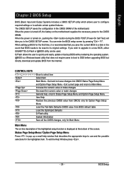
... to the CMOS SETUP screen. Status Page Setup Menu / Option Page Setup Menu Press to the CMOS SRAM. If you to a new BIOS, either GIGABYTE's Q-Flash or @BIOS utility can enter the BIOS setup screen by pressing "Ctrl + F1". When the power is turned on -line description of the...System Information Save all the CMOS changes, only for the highlighted item. Exit current page and return to a disk in the CMOS SRAM of the motherboard. To exit the Help Window press . - 29 - Quit and not save the current BIOS to Main Menu Increase the numeric value or make changes...
... to the CMOS SETUP screen. Status Page Setup Menu / Option Page Setup Menu Press to the CMOS SRAM. If you to a new BIOS, either GIGABYTE's Q-Flash or @BIOS utility can enter the BIOS setup screen by pressing "Ctrl + F1". When the power is turned on -line description of the...System Information Save all the CMOS changes, only for the highlighted item. Exit current page and return to a disk in the CMOS SRAM of the motherboard. To exit the Help Window press . - 29 - Quit and not save the current BIOS to Main Menu Increase the numeric value or make changes...
User Manual
Page 30
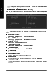
... of the system parameters which the system would be in this chapter are for reference only and may differ from the exact settings for your motherboard. The Main Menu (For example: BIOS Ver. : E8) Once you wish to accept or enter the sub-menu. English The BIOS Setup menus described in... and frequency ratio. „ Top Performance If you enter Award BIOS CMOS Setup Utility, the Main Menu (as figure below) will appear on the screen. GA-K8VT800-RH Motherboard - 30 -
... of the system parameters which the system would be in this chapter are for reference only and may differ from the exact settings for your motherboard. The Main Menu (For example: BIOS Ver. : E8) Once you wish to accept or enter the sub-menu. English The BIOS Setup menus described in... and frequency ratio. „ Top Performance If you enter Award BIOS CMOS Setup Utility, the Main Menu (as figure below) will appear on the screen. GA-K8VT800-RH Motherboard - 30 -
User Manual
Page 32
... correct settings. Jan. Day The day, from Sun to set the access mode for automatic device detection. The four options are : Large/Auto(default:Auto) GA-K8VT800-RH Motherboard - 32 - Week Month The week, from 1 to select this if no IDE devices are used and the system will skip the automatic detection step...
... correct settings. Jan. Day The day, from Sun to set the access mode for automatic device detection. The four options are : Large/Auto(default:Auto) GA-K8VT800-RH Motherboard - 32 - Week Month The week, from 1 to select this if no IDE devices are used and the system will skip the automatic detection step...

User Manual
Page 33
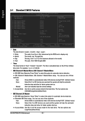
...types of memory located above 1 MB in the system. Halt on The category determines whether the computer will be labeled on the motherboard. Memory The category is display-only which is detected during the POST. Total Memory This item displays the memory size that has ... If a hard disk has not been installed, select NONE and press . Hard drive information should be prompted. Enter the appropriate option based on the motherboard, or 640K for a keyboard error; None No floppy drive installed 360K, 5.25" 5.25 inch PC-type standard drive; 360K byte capacity. 1.2M...
...types of memory located above 1 MB in the system. Halt on The category determines whether the computer will be labeled on the motherboard. Memory The category is display-only which is detected during the POST. Total Memory This item displays the memory size that has ... If a hard disk has not been installed, select NONE and press . Hard drive information should be prompted. Enter the appropriate option based on the motherboard, or 640K for a keyboard error; None No floppy drive installed 360K, 5.25" 5.25 inch PC-type standard drive; 360K byte capacity. 1.2M...

User Manual
Page 34
... system can not boot and can not access to Setup will be denied if the correct password is not entered at the prompt. (Default value) GA-K8VT800-RH Motherboard - 34 - Setup The system will boot, but access to Setup page will be denied if the correct password is not entered at the prompt...
... system can not boot and can not access to Setup will be denied if the correct password is not entered at the prompt. (Default value) GA-K8VT800-RH Motherboard - 34 - Setup The system will boot, but access to Setup page will be denied if the correct password is not entered at the prompt...


