
User Manual
Page 1
The author assumes no responsibility for any labels on motherboard, this may void the warranty of this motherboard. Notice Please do not remove any errors or omissions that may be out of date before publication of GBT. Due to update the ... nor does the author make a commitment to rapid change in technology, some of the specifications might be reproduced or transmitted in this booklet. GA-K8VNXP AMD Socket 754 Processor Motherboard User's Manual Rev. 1002 12ME-K8VNXP-1002 Copyright © 2005 GIGABYTE TECHNOLOGY CO., LTD Copyright by GIGA-BYTE TECHNOLOGY CO., LTD. ("GBT").
The author assumes no responsibility for any labels on motherboard, this may void the warranty of this motherboard. Notice Please do not remove any errors or omissions that may be out of date before publication of GBT. Due to update the ... nor does the author make a commitment to rapid change in technology, some of the specifications might be reproduced or transmitted in this booklet. GA-K8VNXP AMD Socket 754 Processor Motherboard User's Manual Rev. 1002 12ME-K8VNXP-1002 Copyright © 2005 GIGABYTE TECHNOLOGY CO., LTD Copyright by GIGA-BYTE TECHNOLOGY CO., LTD. ("GBT").

User Manual
Page 3
Motherboard GA-K8VNXP August 29, 2003
Motherboard GA-K8VNXP August 29, 2003

User Manual
Page 4
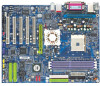
English Read Me First! Please insert an AGP 4X/8X card. If your AGP card is not supported by VIA K8T800. GA-K8VNXP Motherboard - 4 - AGP 4X/8X notch Caution: AGP 2X card is AGP 4X/8X. You might experience system unable to boot up normally. When you installing AGP card, please make sure your AGP card has "AGP 4X/8X (1.5V) notch" (show below), please make sure the following notice is fully understood and practiced.
English Read Me First! Please insert an AGP 4X/8X card. If your AGP card is not supported by VIA K8T800. GA-K8VNXP Motherboard - 4 - AGP 4X/8X notch Caution: AGP 2X card is AGP 4X/8X. You might experience system unable to boot up normally. When you installing AGP card, please make sure your AGP card has "AGP 4X/8X (1.5V) notch" (show below), please make sure the following notice is fully understood and practiced.

User Manual
Page 5
... near by the edges and try not touch the IC chips, leads or connectors, or other components. 4. Installing the motherboard to the mounting holes. In this way you can still attach the motherboard to a metal object, such as the power supply case. 3. Be careful, don't let the screw contact any printed... circuit write or parts on the motherboard. Sometimes you plug in or remove the ATX power connector on the PCB that the ATX power supply is switched off , so be careful of ...
... near by the edges and try not touch the IC chips, leads or connectors, or other components. 4. Installing the motherboard to the mounting holes. In this way you can still attach the motherboard to a metal object, such as the power supply case. 3. Be careful, don't let the screw contact any printed... circuit write or parts on the motherboard. Sometimes you plug in or remove the ATX power connector on the PCB that the ATX power supply is switched off , so be careful of ...

User Manual
Page 6
English Table of Content Read Me First 4 Chapter 1 Introduction 8 Item Checklist 8 Features Summary 8 GA-K8VNXP Motherboard Layout 11 Block Diagram 12 Chapter 2 Hardware Installation Process 15 Step 1: Install the Central Processing Unit (CPU 16 Step 2: Install Memory Modules 18 Step 3: Install ... (For example: BIOS Ver. : F1a 40 Standard CMOS Features 42 Advanced BIOS Features 45 Integrated Peripherals 47 Power Management Setup 52 PnP/PCI Configurations 55 GA-K8VNXP Motherboard - 6 -
English Table of Content Read Me First 4 Chapter 1 Introduction 8 Item Checklist 8 Features Summary 8 GA-K8VNXP Motherboard Layout 11 Block Diagram 12 Chapter 2 Hardware Installation Process 15 Step 1: Install the Central Processing Unit (CPU 16 Step 2: Install Memory Modules 18 Step 3: Install ... (For example: BIOS Ver. : F1a 40 Standard CMOS Features 42 Advanced BIOS Features 45 Integrated Peripherals 47 Power Management Setup 52 PnP/PCI Configurations 55 GA-K8VNXP Motherboard - 6 -
User Manual
Page 8
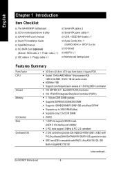
...4cm ATX size form factor, 4 layers PCB y Socket 754 for motherboard driver & utility GA-K8VNXP user's manual Quick PC Installation Guide GigaRAID manual GC-SATA Card (optional) (Manual; English Chapter 1 Introduction Item Checklist The GA-K8VNXP motherboard CD for AMD Althlon™ 64 processor (K8) 128K L1&... 256K / 512K / 1M L2 cache on die y 800MHz FSB y Support core frequencies in GigaRAID IT8212F to be continued... GA-K8VNXP Motherboard - 8 - SATA cable x 1; Bus/AGP/VLINK Controller y VIA VT8237R Integrated Peripheral Controller (PSIPC) y 3 184-pin DDR DIMM sockets y ...
...4cm ATX size form factor, 4 layers PCB y Socket 754 for motherboard driver & utility GA-K8VNXP user's manual Quick PC Installation Guide GigaRAID manual GC-SATA Card (optional) (Manual; English Chapter 1 Introduction Item Checklist The GA-K8VNXP motherboard CD for AMD Althlon™ 64 processor (K8) 128K L1&... 256K / 512K / 1M L2 cache on die y 800MHz FSB y Support core frequencies in GigaRAID IT8212F to be continued... GA-K8VNXP Motherboard - 8 - SATA cable x 1; Bus/AGP/VLINK Controller y VIA VT8237R Integrated Peripheral Controller (PSIPC) y 3 184-pin DDR DIMM sockets y ...

User Manual
Page 10
GA-K8VNXP Motherboard - 10 - We don't recommend you to set the system bus frequency over -current protection y Supports Thermal Shutdown function y Supports @BIOS y Supports EasyTune 4 y Over Voltage (CPU/...
GA-K8VNXP Motherboard - 10 - We don't recommend you to set the system bus frequency over -current protection y Supports Thermal Shutdown function y Supports @BIOS y Supports EasyTune 4 y Over Voltage (CPU/...

User Manual
Page 12
Bus 800MHz 5 PCI PCICLK (33MHz) LAN2 RJ45 LAN1 RJ45 VIA K8T800 DDR RAM 400/333/266/200MHz 33 MHz 14.318 MHz RTL8201 RTL8110S BIOS GigaRAID IT8212 VIA VT8237 LPC BUS IT8705 Ti1394B IR Game Port Floppy LPT Port AC97 Link IDE3 IDE4 2 Serial ATA 6 Channel CODEC 8 USB Ports 24 MHz 33 MHz 3 IEEE1394 ATA33/66/100/133 IDE Channels PS/2 KB/Mouse 2 COM Ports MIC LINE-IN LINE-OUT GA-K8VNXP Motherboard - 12 - English Block Diagram AGPCLK (66MHz) AGP 4X/8X AMD AlthlonTM 64 processor (K8) CPUCLK+/- (200MHz) H.T.
Bus 800MHz 5 PCI PCICLK (33MHz) LAN2 RJ45 LAN1 RJ45 VIA K8T800 DDR RAM 400/333/266/200MHz 33 MHz 14.318 MHz RTL8201 RTL8110S BIOS GigaRAID IT8212 VIA VT8237 LPC BUS IT8705 Ti1394B IR Game Port Floppy LPT Port AC97 Link IDE3 IDE4 2 Serial ATA 6 Channel CODEC 8 USB Ports 24 MHz 33 MHz 3 IEEE1394 ATA33/66/100/133 IDE Channels PS/2 KB/Mouse 2 COM Ports MIC LINE-IN LINE-OUT GA-K8VNXP Motherboard - 12 - English Block Diagram AGPCLK (66MHz) AGP 4X/8X AMD AlthlonTM 64 processor (K8) CPUCLK+/- (200MHz) H.T.

User Manual
Page 16
... matches up to inserting the processor. Please make sure the CPU type is designated on the processor by the motherboard. 5. English Step 1: Install the Central Processing Unit (CPU) Before installing the processor and cooling fan, adhere... overheat without the heatsink and/or fan, resulting in Figure 1 & Figure 2.(90o to the plane of the motherboard) prior to a triangle on the socket as shown in permanent irreparable damage. 2. The processor will cause improper installation... rod to the unlocked position as shown in four main steps: Step 1-1. GA-K8VNXP Motherboard Figure 3.
... matches up to inserting the processor. Please make sure the CPU type is designated on the processor by the motherboard. 5. English Step 1: Install the Central Processing Unit (CPU) Before installing the processor and cooling fan, adhere... overheat without the heatsink and/or fan, resulting in Figure 1 & Figure 2.(90o to the plane of the motherboard) prior to a triangle on the socket as shown in permanent irreparable damage. 2. The processor will cause improper installation... rod to the unlocked position as shown in four main steps: Step 1-1. GA-K8VNXP Motherboard Figure 3.

User Manual
Page 17
... strong adhesive forces between your CPU and heatsink. (The CPU cooling fan might pull the processor out of Thermal Grease to the header on the motherboard as shown in Figure 5&6. Align the heatsink assembly with the support frame mating with the cooling fan, and might damage the processor. Hardware Installation Process...
... strong adhesive forces between your CPU and heatsink. (The CPU cooling fan might pull the processor out of Thermal Grease to the header on the motherboard as shown in Figure 5&6. Align the heatsink assembly with the support frame mating with the cooling fan, and might damage the processor. Hardware Installation Process...

User Manual
Page 18
...-bitsx4 banks) Size Per CS 64 Mbyte 32 Mbyte 128 Mbyte 64 Mbyte 256 Mbyte 128 Mbyte 512 Mbyte 256 Mbyte 1 Gbyte 512 Mbyte GA-K8VNXP Motherboard - 18 - The motherboard has 3 dual inline memory module (DIMM) sockets. The DIMM module can only fit in one direction due to the one direction due to the...
...-bitsx4 banks) Size Per CS 64 Mbyte 32 Mbyte 128 Mbyte 64 Mbyte 256 Mbyte 128 Mbyte 512 Mbyte 256 Mbyte 1 Gbyte 512 Mbyte GA-K8VNXP Motherboard - 18 - The motherboard has 3 dual inline memory module (DIMM) sockets. The DIMM module can only fit in one direction due to the one direction due to the...

User Manual
Page 20
... to the onboard AGP slot and press firmly down on the slot. Power on the card are indeed seated in motherboard. 4. Please align the AGP card to install / uninstall the AGP card. GA-K8VNXP Motherboard - 20 - Press the expansion card firmly into the computer. 2. Install related driver from the computer. 3. Replace your AGP card...
... to the onboard AGP slot and press firmly down on the slot. Power on the card are indeed seated in motherboard. 4. Please align the AGP card to install / uninstall the AGP card. GA-K8VNXP Motherboard - 20 - Press the expansion card firmly into the computer. 2. Install related driver from the computer. 3. Replace your AGP card...

User Manual
Page 21
... with the clip. 4. Hardware Installation Process How to remove the K8DPS. - 21 - The K8DPS can work in a Dual Power System: • Parallel Mode : K8DPS and motherboard CPU power can only fit in one direction. 2. Insert the K8DPS vertically into the socket and then push it down. 3. Reverse the installation steps if... System) is K8 DPS ? A cool stylish neon blue K8DPS that supply a total 6-phase power circuit design, delivers a high durable power design for the new generation motherboard.
... with the clip. 4. Hardware Installation Process How to remove the K8DPS. - 21 - The K8DPS can work in a Dual Power System: • Parallel Mode : K8DPS and motherboard CPU power can only fit in one direction. 2. Insert the K8DPS vertically into the socket and then push it down. 3. Reverse the installation steps if... System) is K8 DPS ? A cool stylish neon blue K8DPS that supply a total 6-phase power circuit design, delivers a high durable power design for the new generation motherboard.

User Manual
Page 22
... 1 LAN1 USB 2 USB 3 Before you connect your device(s) into USB connector(s), please make sure your device (s) such as USB keyboard,mouse, scanner, zip, speaker...etc. GA-K8VNXP Motherboard - 22 - Also make sure your OS supports USB controller. For more information please contact your OS does not support USB controller, please contact OS vendor...
... 1 LAN1 USB 2 USB 3 Before you connect your device(s) into USB connector(s), please make sure your device (s) such as USB keyboard,mouse, scanner, zip, speaker...etc. GA-K8VNXP Motherboard - 22 - Also make sure your OS supports USB controller. For more information please contact your OS does not support USB controller, please contact OS vendor...

User Manual
Page 24
English Step 4-2: Connectors Introduction 1 3 2 7 13 5 6 21 18 14 16 17 22 15 1) ATX_12V 2) ATX (Power Connector) 3) CPU_FAN 4) SYS_FAN 5) PWR_FAN 6) NB_FAN 7) FDD 8) IDE1 / IDE2 9) IDE3 / IDE4 10) SATA0 / SATA1 11) F_PANEL 12) PWR_LED 13) RAM_LED 8 28 10 4 24 23 25 9 12 20 19 11 14) F_AUDIO 15) SUR_CEN 16) SPDIF_IO 17) CD_IN 18) AUX_IN 19) F_USB1 / F_USB2 20) F1_1394 / F2_1394 21) IR 22) GAME 23) INFO_LINK 24) CLR_PWD 25) BAT GA-K8VNXP Motherboard - 24 -
English Step 4-2: Connectors Introduction 1 3 2 7 13 5 6 21 18 14 16 17 22 15 1) ATX_12V 2) ATX (Power Connector) 3) CPU_FAN 4) SYS_FAN 5) PWR_FAN 6) NB_FAN 7) FDD 8) IDE1 / IDE2 9) IDE3 / IDE4 10) SATA0 / SATA1 11) F_PANEL 12) PWR_LED 13) RAM_LED 8 28 10 4 24 23 25 9 12 20 19 11 14) F_AUDIO 15) SUR_CEN 16) SPDIF_IO 17) CD_IN 18) AUX_IN 19) F_USB1 / F_USB2 20) F1_1394 / F2_1394 21) IR 22) GAME 23) INFO_LINK 24) CLR_PWD 25) BAT GA-K8VNXP Motherboard - 24 -

User Manual
Page 25
...) AC power cord should only be connected to your power supply unit after ATX power cable and other related devices are firmly connected to the motherboard. Pin No. Definition 1 3.3V 2 3.3V 3 GND 11 1 4 VCC 5 GND 6 VCC 7 GND 8 Power Good 9 5V SB (stand by +5V) 10 +12V 11 3.3V 12 -12V 13...
...) AC power cord should only be connected to your power supply unit after ATX power cable and other related devices are firmly connected to the motherboard. Pin No. Definition 1 3.3V 2 3.3V 3 GND 11 1 4 VCC 5 GND 6 VCC 7 GND 8 Power Good 9 5V SB (stand by +5V) 10 +12V 11 3.3V 12 -12V 13...

User Manual
Page 26
English 3) CPU_FAN (CPU Fan Connector) Please note, a proper installation of the CPU cooler is essential to lower the system temperature. Pin No. Definition 1 1 GND 2 +12V 3 Sense GA-K8VNXP Motherboard - 26 - Definition 1 1 GND 2 +12V 3 Sense 4) SYS_FAN (System Fan Connector) This connector allows you to link with the cooling fan on the system case to prevent the CPU from running under abnormal condition or damaged by overheating. The CPU fan connector supports Max. Pin No. current up to 600 mA.
English 3) CPU_FAN (CPU Fan Connector) Please note, a proper installation of the CPU cooler is essential to lower the system temperature. Pin No. Definition 1 1 GND 2 +12V 3 Sense GA-K8VNXP Motherboard - 26 - Definition 1 1 GND 2 +12V 3 Sense 4) SYS_FAN (System Fan Connector) This connector allows you to link with the cooling fan on the system case to prevent the CPU from running under abnormal condition or damaged by overheating. The CPU fan connector supports Max. Pin No. current up to 600 mA.

User Manual
Page 28
English 7) FDD (Floppy Connector) Please connect the floppy drive ribbon cables to IDE2. It supports 360K, 1.2M, 720K, 1.44M and 2.88M bytes floppy disk types. The red stripe of the ribbon cable must be the same side with the Pin1. 40 39 GA-K8VNXP Motherboard 2 IDE2 1 IDE1 - 28 - The red stripe of the ribbon cable must be the same side with the Pin1. 34 33 2 1 8) IDE1 / IDE2 (IDE1 / IDE2 Connector) Important Notice: Please connect first hard disk to IDE1 and connect CD-ROM to FDD.
English 7) FDD (Floppy Connector) Please connect the floppy drive ribbon cables to IDE2. It supports 360K, 1.2M, 720K, 1.44M and 2.88M bytes floppy disk types. The red stripe of the ribbon cable must be the same side with the Pin1. 40 39 GA-K8VNXP Motherboard 2 IDE2 1 IDE1 - 28 - The red stripe of the ribbon cable must be the same side with the Pin1. 34 33 2 1 8) IDE1 / IDE2 (IDE1 / IDE2 Connector) Important Notice: Please connect first hard disk to IDE1 and connect CD-ROM to FDD.

User Manual
Page 30
...- Pin 3: NC Pin 4: Data(-) Open: Normal Operation Close: Reset Hardware System Open: Normal Operation Close: Power On/Off Pin 1: LED anode(+) Pin 2: LED cathode(-) NC GA-K8VNXP Motherboard - 30 - RESRES+ NC Reset Switch IDE Hard Disk Active LED HD (IDE Hard Disk Active LED) (Blue) SPK (Speaker Connector) (Amber) RES (Reset Switch) (Green...
...- Pin 3: NC Pin 4: Data(-) Open: Normal Operation Close: Reset Hardware System Open: Normal Operation Close: Power On/Off Pin 1: LED anode(+) Pin 2: LED cathode(-) NC GA-K8VNXP Motherboard - 30 - RESRES+ NC Reset Switch IDE Hard Disk Active LED HD (IDE Hard Disk Active LED) (Blue) SPK (Speaker Connector) (Amber) RES (Reset Switch) (Green...

User Manual
Page 32
... audio connector, please contact your nearest dealer for optional SUR_CEN cable. 26 15 Pin No. 1 2 3 4 5 6 Definition SUR OUTL SUR OUTR GND No Pin CENTER_OUT BASS_OUT GA-K8VNXP Motherboard - 32 - To find out if the chassis you can have front audio connector. Also please make sure the pin assigment on the cable is the...
... audio connector, please contact your nearest dealer for optional SUR_CEN cable. 26 15 Pin No. 1 2 3 4 5 6 Definition SUR OUTL SUR OUTR GND No Pin CENTER_OUT BASS_OUT GA-K8VNXP Motherboard - 32 - To find out if the chassis you can have front audio connector. Also please make sure the pin assigment on the cable is the...


