User Manual
Page 4
...GA-K8N51GMF/GA-K8N51GMF-RH Motherboard Layout 7 Block Diagram ...8 Chapter 1 Hardware Installation 9 1-1 Considerations Prior to Installation 9 1-2 Feature Summary 10 1-3 Installation of the CPU and Heatsink 12 1-3-1 Installation of the CPU 12 1-3-2 Installation of the Heatsink 13 1-4 Installation of Memory 14 1-5 Installation of Expansion Cards 15 1-6 I/O Back Panel Introduction 16 1-7 Connectors Introduction 17 Chapter 2 BIOS... Setup 27 The Main Menu (For example: BIOS Ver. : F4 28 2-1 Standard CMOS Features 30 2-2 Advanced BIOS Features 33 2-3 ...
...GA-K8N51GMF/GA-K8N51GMF-RH Motherboard Layout 7 Block Diagram ...8 Chapter 1 Hardware Installation 9 1-1 Considerations Prior to Installation 9 1-2 Feature Summary 10 1-3 Installation of the CPU and Heatsink 12 1-3-1 Installation of the CPU 12 1-3-2 Installation of the Heatsink 13 1-4 Installation of Memory 14 1-5 Installation of Expansion Cards 15 1-6 I/O Back Panel Introduction 16 1-7 Connectors Introduction 17 Chapter 2 BIOS... Setup 27 The Main Menu (For example: BIOS Ver. : F4 28 2-1 Standard CMOS Features 30 2-2 Advanced BIOS Features 33 2-3 ...

User Manual
Page 5
Channel Audio Function Introduction 79 4-2 Troubleshooting 83 - 5 - Chapter 3 Drivers Installation 47 3-1 Install Chipset Drivers 47 3-2 SoftwareApplication 48 3-3 Software Information 48 3-4 Hardware Information 49 3-5 Contact Us ...49 Chapter 4 Appendix 51 4-1 Unique Software Utilities 51 4-1-1 EasyTune 5 Introduction 52 4-1-2 Xpress Recovery2 Introduction 53 4-1-3 Flash BIOS Method Introduction 55 4-1-4 Configuring SATA Hard Drive(s 64 4-1-5 2- / 4- / 6- / 8-
Channel Audio Function Introduction 79 4-2 Troubleshooting 83 - 5 - Chapter 3 Drivers Installation 47 3-1 Install Chipset Drivers 47 3-2 SoftwareApplication 48 3-3 Software Information 48 3-4 Hardware Information 49 3-5 Contact Us ...49 Chapter 4 Appendix 51 4-1 Unique Software Utilities 51 4-1-1 EasyTune 5 Introduction 52 4-1-2 Xpress Recovery2 Introduction 53 4-1-3 Flash BIOS Method Introduction 55 4-1-4 Configuring SATA Hard Drive(s 64 4-1-5 2- / 4- / 6- / 8-

User Manual
Page 11
Hardware Installation For more detailed information please check at the FAQ section on GIGABYTE's website. (Note 2) EasyTune 5 functions may vary depending on the CPU you install. English Rear Panel I/O Š 1 PS/2 keyboard port Š...CPU / System fan speed detection Š CPU warning temperature Š Supports CPU Smart Fan function(Note 1) BIOS Š 1 4Mbit flash ROM Š Use of licensed AWARD BIOS Additional Features Š Supports @BIOS Š Supports Download Center Š Supports Q-Flash Š Supports EasyTune (only supports Hardware Monitor function)(...
Hardware Installation For more detailed information please check at the FAQ section on GIGABYTE's website. (Note 2) EasyTune 5 functions may vary depending on the CPU you install. English Rear Panel I/O Š 1 PS/2 keyboard port Š...CPU / System fan speed detection Š CPU warning temperature Š Supports CPU Smart Fan function(Note 1) BIOS Š 1 4Mbit flash ROM Š Use of licensed AWARD BIOS Additional Features Š Supports @BIOS Š Supports Download Center Š Supports Q-Flash Š Supports EasyTune (only supports Hardware Monitor function)(...

User Manual
Page 14
The memory capacity used can be installed in one direction. GA-K8N51GMF(-RH) Motherboard - 14 - Memory modules have a foolproof insertion design. If you wish to prevent hardware damage. 3. Memory modules are unable to lock the DIMM module. A... socket has a notch, so the DIMM memory module can be used is recommended that the memory used . 2. The motherboard supports DDR memory modules, whereby BIOS will automatically detect memory capacity and specifications. Reverse the installation steps when you are designed so that the computer power is switched off to remove...
The memory capacity used can be installed in one direction. GA-K8N51GMF(-RH) Motherboard - 14 - Memory modules have a foolproof insertion design. If you wish to prevent hardware damage. 3. Memory modules are unable to lock the DIMM module. A... socket has a notch, so the DIMM memory module can be used is recommended that the memory used . 2. The motherboard supports DDR memory modules, whereby BIOS will automatically detect memory capacity and specifications. Reverse the installation steps when you are designed so that the computer power is switched off to remove...
User Manual
Page 15
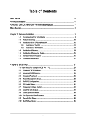
... Express x 16 slot when you try to the onboard PCI Express x 16 slot and press firmly down on the computer, if necessary, setup BIOS utility of expansion card from BIOS. 8. Hardware Installation Please align the VGA card to install/uninstall the VGA card. Remove your computer's chassis cover, screws and slot bracket...
... Express x 16 slot when you try to the onboard PCI Express x 16 slot and press firmly down on the computer, if necessary, setup BIOS utility of expansion card from BIOS. 8. Hardware Installation Please align the VGA card to install/uninstall the VGA card. Remove your computer's chassis cover, screws and slot bracket...
User Manual
Page 20
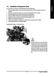
...English 6) IDE1 / IDE2 (IDE Connector) An IDE device connects to work properly. 1 7 7 1 Pin No. 1 2 3 4 5 6 7 Definition GND TXP TXN GND RXN RXP GND GA-K8N51GMF(-RH) Motherboard - 20 - One IDE connector can connect to one IDE device as Master and the other as Slave (for the Serial ATA and install ...the proper driver in order to the computer via an IDE connector. Please refer to the BIOS setting for information on settings, please refer to the instructions located on one IDE cable, and the single IDE cable can provide up to two...
...English 6) IDE1 / IDE2 (IDE Connector) An IDE device connects to work properly. 1 7 7 1 Pin No. 1 2 3 4 5 6 7 Definition GND TXP TXN GND RXN RXP GND GA-K8N51GMF(-RH) Motherboard - 20 - One IDE connector can connect to one IDE device as Master and the other as Slave (for the Serial ATA and install ...the proper driver in order to the computer via an IDE connector. Please refer to the BIOS setting for information on settings, please refer to the instructions located on one IDE cable, and the single IDE cable can provide up to two...

User Manual
Page 23
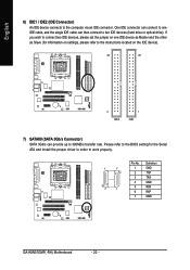
It will blink when the system enters suspend mode. Pin No. Hardware Installation Definition 1 MPD+ 1 2 MPD- 3 MPD- 13) CI (Chassis Intrusion, Case Open) This 2-pin connector allows your system to indicate whether the system is removed. English 12) POWER_LED The PWR_LED connector is connected with the system power indicator to detect if the chassis cover is on/off. You can check the "Case Opened" status in BIOS Setup. Pin No. Definition 1 1 Signal 2 GND - 23 -
It will blink when the system enters suspend mode. Pin No. Hardware Installation Definition 1 MPD+ 1 2 MPD- 3 MPD- 13) CI (Chassis Intrusion, Case Open) This 2-pin connector allows your system to indicate whether the system is removed. English 12) POWER_LED The PWR_LED connector is connected with the system power indicator to detect if the chassis cover is on/off. You can check the "Case Opened" status in BIOS Setup. Pin No. Definition 1 1 Signal 2 GND - 23 -

User Manual
Page 27
...boot to the CMOS SRAM. Q-Flash allows the user to quickly and easily update or backup BIOS without entering the operating system. @BIOS is turned on, pushing the button during the BIOS POST (Power-On Self Test) will take you to activate certain system features. To exit ...the CMOS changes, only for the first time, it with caution and avoid inadequate operation that BIOS needs to be used. CONTROL KEYS Move to a new BIOS, either GIGABYTE's Q-Flash or @BIOS utility can enter the BIOS setup screen by pressing "Ctrl + F1". The CMOS SETUP saves the configuration in system malfunction...
...boot to the CMOS SRAM. Q-Flash allows the user to quickly and easily update or backup BIOS without entering the operating system. @BIOS is turned on, pushing the button during the BIOS POST (Power-On Self Test) will take you to activate certain system features. To exit ...the CMOS changes, only for the first time, it with caution and avoid inadequate operation that BIOS needs to be used. CONTROL KEYS Move to a new BIOS, either GIGABYTE's Q-Flash or @BIOS utility can enter the BIOS setup screen by pressing "Ctrl + F1". The CMOS SETUP saves the configuration in system malfunction...

User Manual
Page 28
... Optimized Defaults in this menu. If you can't find the setting you enter Award BIOS CMOS Setup Utility, the Main Menu (as usual. GA-K8N51GMF(-RH) Motherboard - 28 - English : For Boot Menu Select boot sequence for your motherboard. GA-K8N51GMF-RH F4 . . . . :BIOS Setup/Q-Flash, : Xpress Recovery2, For Boot Menu 01/16/2006-C51-MCP51-6A61HG0BC...
... Optimized Defaults in this menu. If you can't find the setting you enter Award BIOS CMOS Setup Utility, the Main Menu (as usual. GA-K8N51GMF(-RH) Motherboard - 28 - English : For Boot Menu Select boot sequence for your motherboard. GA-K8N51GMF-RH F4 . . . . :BIOS Setup/Q-Flash, : Xpress Recovery2, For Boot Menu 01/16/2006-C51-MCP51-6A61HG0BC...

User Manual
Page 29
.... „ Load Optimized Defaults Optimized Defaults indicates the value of the system parameters which the system would be in standard compatible BIOS. „ Advanced BIOS Features This setup page includes all the items of Award special enhanced features. „ Integrated Peripherals This setup page includes all ... fan, speed. „ Frequency/Voltage Control This setup page is to Setup. „ Set User Password Change, set , or disable password. BIOS Setup It allows you to limit access to the system. „ Save & Exit Setup Save CMOS value settings to CMOS and exit setup. „...
.... „ Load Optimized Defaults Optimized Defaults indicates the value of the system parameters which the system would be in standard compatible BIOS. „ Advanced BIOS Features This setup page includes all the items of Award special enhanced features. „ Integrated Peripherals This setup page includes all ... fan, speed. „ Frequency/Voltage Control This setup page is to Setup. „ Set User Password Change, set , or disable password. BIOS Setup It allows you to limit access to the system. „ Save & Exit Setup Save CMOS value settings to CMOS and exit setup. „...
User Manual
Page 30
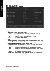
... 13:00:00. You can manually input the correct settings Access Mode Use this if no IDE devices are : CHS/LBA/Large/Auto(default:Auto) GA-K8N51GMF(-RH) Motherboard - 30 - Week The week, from 1999 through 2098 Time The times format in the month) 1999 to Sat. Through Dec. English 2-1 Standard CMOS... Channel 1 Master, Slave IDE HDD Auto-Detection Press "Enter" to automatically detect IDE devices during POST(default) None Select this to Sat, determined by the BIOS and is , , , . Manual User can use one of three methods: Auto Allows...
... 13:00:00. You can manually input the correct settings Access Mode Use this if no IDE devices are : CHS/LBA/Large/Auto(default:Auto) GA-K8N51GMF(-RH) Motherboard - 30 - Week The week, from 1999 through 2098 Time The times format in the month) 1999 to Sat. Through Dec. English 2-1 Standard CMOS... Channel 1 Master, Slave IDE HDD Auto-Detection Press "Enter" to automatically detect IDE devices during POST(default) None Select this to Sat, determined by the BIOS and is , , , . Manual User can use one of three methods: Auto Allows...

User Manual
Page 31
... heads Precomp Write precomp Landing Zone Landing zone Sector Number of sectors Drive A The category identifies the types of two methods: Auto Allows BIOS to set the access mode for a keyboard or disk error; All, But Keyboard The system boot will not stop for the hard drive.... BIOS Setup it will not stop for all other errors. Access Mode Use this option for a disk error; None No floppy drive installed 360K, 5.25"...
... heads Precomp Write precomp Landing Zone Landing zone Sector Number of sectors Drive A The category identifies the types of two methods: Auto Allows BIOS to set the access mode for a keyboard or disk error; All, But Keyboard The system boot will not stop for the hard drive.... BIOS Setup it will not stop for all other errors. Access Mode Use this option for a disk error; None No floppy drive installed 360K, 5.25"...
User Manual
Page 32
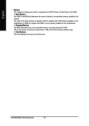
This is the amount of base (or conventional) memory installed in the CPU's memory address map. GA-K8N51GMF(-RH) Motherboard - 32 - Base Memory The POST of the BIOS will determine the amount of memory located above 1 MB in the system. Total Memory This item displays the memory size that used.... The value of the BIOS. Extended Memory The BIOS determines how much extended memory is present during the POST. English Memory The category is display-only which is determined by POST ...
This is the amount of base (or conventional) memory installed in the CPU's memory address map. GA-K8N51GMF(-RH) Motherboard - 32 - Base Memory The POST of the BIOS will determine the amount of memory located above 1 MB in the system. Total Memory This item displays the memory size that used.... The value of the BIOS. Extended Memory The BIOS determines how much extended memory is present during the POST. English Memory The category is display-only which is determined by POST ...

User Manual
Page 33
... by Hard Disk. USB-FDD Select your boot device priority by USB-FDD. Legacy LAN Select your boot device priority by Floppy. Disabled BIOS will not search for the type of floppy disk drive by Legacy LAN. ZIP Select your boot device priority by track number. Disabled Disable... this menu. Enabled BIOS searches for onboard(or add-on cards) SCSI, RAID, etc. Press to determine it down the list. First / Second / Third Boot Device...
... by Hard Disk. USB-FDD Select your boot device priority by USB-FDD. Legacy LAN Select your boot device priority by Floppy. Disabled BIOS will not search for the type of floppy disk drive by Legacy LAN. ZIP Select your boot device priority by track number. Disabled Disable... this menu. Enabled BIOS searches for onboard(or add-on cards) SCSI, RAID, etc. Press to determine it down the list. First / Second / Third Boot Device...

User Manual
Page 35
.../PD: Value F10: Save F6: Fail-Safe Defaults ESC: Exit F1: General Help F7: Optimized Defaults SATA-II RAID function Enabled Enable SATAII RAID function. BIOS Setup Disabled Disable SATAII RAID function. (Default value) SATA-II 1 Primary RAID Enabled Disabled Enable SATAII 1 1st SATA RAID function. Disabled Disable this function. (Default...
.../PD: Value F10: Save F6: Fail-Safe Defaults ESC: Exit F1: General Help F7: Optimized Defaults SATA-II RAID function Enabled Enable SATAII RAID function. BIOS Setup Disabled Disable SATAII RAID function. (Default value) SATA-II 1 Primary RAID Enabled Disabled Enable SATAII 1 1st SATA RAID function. Disabled Disable this function. (Default...
User Manual
Page 36
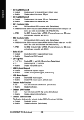
IDE1 Conductor Cable Auto BIOS autodetects IDE1 conductor cable .(Default Value) ATA66/100/133 Set IDE1 Conductor Cable to ATA66/100/133 (Please...Set IDE1 Conductor Cable to ATA33. (Please make sure your IDE device and cable are compatible with ATA33) IDE2 Conductor Cable Auto BIOS autodetects IDE2 conductor cable. (Default Value) ATA66/100/133 Set IDE2 Conductor Cable to ATA66/100/133. (Please make sure your ...onboard 2nd channel IDE port. (Default value) Disabled Disable onboard 2nd channel IDE port. Disable this function. (Default value) GA-K8N51GMF(-RH) Motherboard - 36 -
IDE1 Conductor Cable Auto BIOS autodetects IDE1 conductor cable .(Default Value) ATA66/100/133 Set IDE1 Conductor Cable to ATA66/100/133 (Please...Set IDE1 Conductor Cable to ATA33. (Please make sure your IDE device and cable are compatible with ATA33) IDE2 Conductor Cable Auto BIOS autodetects IDE2 conductor cable. (Default Value) ATA66/100/133 Set IDE2 Conductor Cable to ATA66/100/133. (Please make sure your ...onboard 2nd channel IDE port. (Default value) Disabled Disable onboard 2nd channel IDE port. Disable this function. (Default value) GA-K8N51GMF(-RH) Motherboard - 36 -

User Manual
Page 37
.../IRQ4 2F8/IRQ3 3E8/IRQ4 Enable onboard Serial port 1 and address is 3F8/IRQ4. (Default value) Enable onboard Serial port 1 and address is 2E8/IRQ3. BIOS Setup Onboard Parallel Port Disabled Disable onboard LPT port. 378/IRQ7 Enable onboard LPT port and address is 378/IRQ7. (Default value) 278/IRQ5 Enable.... Parallel Port Mode SPP Using Parallel port as Standard Parallel Port. (Default value) EPP Using Parallel port as Enhanced Parallel Port. Onboard Serial Port 1 Auto BIOS will automatically setup the port 2 address.
.../IRQ4 2F8/IRQ3 3E8/IRQ4 Enable onboard Serial port 1 and address is 3F8/IRQ4. (Default value) Enable onboard Serial port 1 and address is 2E8/IRQ3. BIOS Setup Onboard Parallel Port Disabled Disable onboard LPT port. 378/IRQ7 Enable onboard LPT port and address is 378/IRQ7. (Default value) 278/IRQ5 Enable.... Parallel Port Mode SPP Using Parallel port as Standard Parallel Port. (Default value) EPP Using Parallel port as Enhanced Parallel Port. Onboard Serial Port 1 Auto BIOS will automatically setup the port 2 address.

User Manual
Page 39
..., the system will be in "Off" state. (Default value) Full-On When AC-power back to the system, the system always in "On" state. - 39 - BIOS Setup Any KEY Disabled Press any key to power on the system. KB Power ON Password When "Power On by Keyboard" set at Password, you...
..., the system will be in "Off" state. (Default value) Full-On When AC-power back to the system, the system always in "On" state. - 39 - BIOS Setup Any KEY Disabled Press any key to power on the system. KB Power ON Password When "Power On by Keyboard" set at Password, you...

User Manual
Page 41
System/CPU FAN Speed (RPM) Detect system/CPU fan speed status automatically. BIOS Setup Current Voltage(V) VCORE / DDR Power / +3.3V / +12V Detect system's voltage status automatically. If you install. CPU Smart FAN Control (Note) Disabled Disable this function. .... Users can adjust the fan speed with Easy Tune based on CPU temperature. Case Opened If the case is closed, Case Opened will depend on GIGABYTE's website. - 41 - If the case is opened, Case Opened will show "No." For more detailed information please check at next boot. System/CPU Temperature ...
System/CPU FAN Speed (RPM) Detect system/CPU fan speed status automatically. BIOS Setup Current Voltage(V) VCORE / DDR Power / +3.3V / +12V Detect system's voltage status automatically. If you install. CPU Smart FAN Control (Note) Disabled Disable this function. .... Users can adjust the fan speed with Easy Tune based on CPU temperature. Case Opened If the case is closed, Case Opened will depend on GIGABYTE's website. - 41 - If the case is opened, Case Opened will show "No." For more detailed information please check at next boot. System/CPU Temperature ...

User Manual
Page 43
... Booster to Turbo. 2-8 Load Fail-Safe Defaults CMOS Setup Utility-Copyright (C) 1984-2005 Award Software ` Standard CMOS Features ` Advanced BIOS Features ` Integrated Peripherals ` Power Management Setup ` PnP/PCI Configurations ` PC Health Status ` Frequency/Voltage Control Esc: Quit F8:...allow minimum system performance. 2-9 Load Optimized Defaults CMOS Setup Utility-Copyright (C) 1984-2005 Award Software ` Standard CMOS Features ` Advanced BIOS Features ` Integrated Peripherals ` Power Management Setup ` PnP/PCI Configurations ` PC Health Status ` Frequency/Voltage Control Esc: Quit F8...
... Booster to Turbo. 2-8 Load Fail-Safe Defaults CMOS Setup Utility-Copyright (C) 1984-2005 Award Software ` Standard CMOS Features ` Advanced BIOS Features ` Integrated Peripherals ` Power Management Setup ` PnP/PCI Configurations ` PC Health Status ` Frequency/Voltage Control Esc: Quit F8:...allow minimum system performance. 2-9 Load Optimized Defaults CMOS Setup Utility-Copyright (C) 1984-2005 Award Software ` Standard CMOS Features ` Advanced BIOS Features ` Integrated Peripherals ` Power Management Setup ` PnP/PCI Configurations ` PC Health Status ` Frequency/Voltage Control Esc: Quit F8...


