Manual
Page 1
GA-H67MA-UD2H LGA1155 socket motherboard for Intel® Core™ i7 processors/ Intel® Core™ i5 processors/Intel® Core™ i3 processors/ Intel® Pentium® processors/Intel® Celeron® processors User's Manual Rev. 1002 12ME-H67UD2H-1002R
GA-H67MA-UD2H LGA1155 socket motherboard for Intel® Core™ i7 processors/ Intel® Core™ i5 processors/Intel® Core™ i3 processors/ Intel® Pentium® processors/Intel® Celeron® processors User's Manual Rev. 1002 12ME-H67UD2H-1002R
Manual
Page 2
Motherboard GA-H67MA-UD2H Oct. 29, 2010 Motherboard GA-H67MA-UD2H Oct. 29, 2010
Motherboard GA-H67MA-UD2H Oct. 29, 2010 Motherboard GA-H67MA-UD2H Oct. 29, 2010
Manual
Page 3
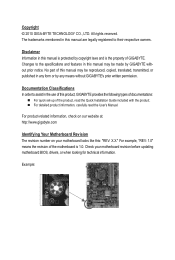
... Disclaimer Information in any form or by any means without prior notice. For example, "REV: 1.0" means the revision of GIGABYTE. Example: Check your motherboard looks like this manual are legally registered to the specifications and features in this manual is 1.0. No part of this manual ...transmitted, or published in this manual may be made by copyright laws and is the property of the motherboard is protected by GIGABYTE without GIGABYTE's prior written permission. Changes to their respective owners. For product-related information, check on our website at: http://...
... Disclaimer Information in any form or by any means without prior notice. For example, "REV: 1.0" means the revision of GIGABYTE. Example: Check your motherboard looks like this manual are legally registered to the specifications and features in this manual is 1.0. No part of this manual ...transmitted, or published in this manual may be made by copyright laws and is the property of the motherboard is protected by GIGABYTE without GIGABYTE's prior written permission. Changes to their respective owners. For product-related information, check on our website at: http://...
Manual
Page 4
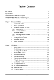
Table of Contents Box Contents...6 Optional Items...6 GA-H67MA-UD2H Motherboard Layout 7 GA-H67MA-UD2H Motherboard Block Diagram 8 Chapter 1 Hardware Installation 9 1-1 Installation Precautions 9 1-2 Product Specifications 10 1-3 Installing the CPU and CPU Cooler 13 1-3-1 Installing the CPU 13 1-3-2 Installing the CPU Cooler ...
Table of Contents Box Contents...6 Optional Items...6 GA-H67MA-UD2H Motherboard Layout 7 GA-H67MA-UD2H Motherboard Block Diagram 8 Chapter 1 Hardware Installation 9 1-1 Installation Precautions 9 1-2 Product Specifications 10 1-3 Installing the CPU and CPU Cooler 13 1-3-1 Installing the CPU 13 1-3-2 Installing the CPU Cooler ...
Manual
Page 6
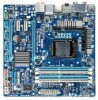
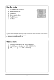
The box contents are for reference only. Box Contents GA-H67MA-UD2H motherboard Motherboard driver disk User's Manual Quick Installation Guide Four SATA cables I/O Shield • The box contents above are subject to change without notice. • The motherboard image is for reference only and the actual items shall depend on the product package you obtain. Optional Items 2-port USB 2.0 bracket (Part No. 12CR1-1UB030-5*R) 2-port SATA power cable (Part No. 12CF1-2SERPW-0*R) COM port cable (Part No. 12CF1-1CM001-3*R) - 6 -
The box contents are for reference only. Box Contents GA-H67MA-UD2H motherboard Motherboard driver disk User's Manual Quick Installation Guide Four SATA cables I/O Shield • The box contents above are subject to change without notice. • The motherboard image is for reference only and the actual items shall depend on the product package you obtain. Optional Items 2-port USB 2.0 bracket (Part No. 12CR1-1UB030-5*R) 2-port SATA power cable (Part No. 12CF1-2SERPW-0*R) COM port cable (Part No. 12CF1-1CM001-3*R) - 6 -
Manual
Page 7
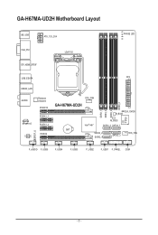
GA-H67MA-UD2H Motherboard Layout KB_USB ATX_12V_2X4 PHASE LED VGA_DVI LGA1155 DP_HDMI_SPDIF USB_ESATA ATX USB30_LAN AUDIO Realtek RTL8111E CODEC Renesas D720200 PCIEX16 PCIEX1_1 PCIEX1_2 PCIEX4 CPU_FAN DDR3_4 GA-H67MA-UD2H CLR_CMOS B_BIOS DDR3_1 DDR3_2 DDR3_3 iTE IT8728 M_BIOS Intel® H67 SATA3_0 SATA3_1 BAT SATA2_2 SATA2_4 SATA2_3 SYS_FAN SPDIF_O F_AUDIO F_USB5 F_USB4 F_USB3 F_USB2 F_USB1 F_PANEL COM - 7 -
GA-H67MA-UD2H Motherboard Layout KB_USB ATX_12V_2X4 PHASE LED VGA_DVI LGA1155 DP_HDMI_SPDIF USB_ESATA ATX USB30_LAN AUDIO Realtek RTL8111E CODEC Renesas D720200 PCIEX16 PCIEX1_1 PCIEX1_2 PCIEX4 CPU_FAN DDR3_4 GA-H67MA-UD2H CLR_CMOS B_BIOS DDR3_1 DDR3_2 DDR3_3 iTE IT8728 M_BIOS Intel® H67 SATA3_0 SATA3_1 BAT SATA2_2 SATA2_4 SATA2_3 SYS_FAN SPDIF_O F_AUDIO F_USB5 F_USB4 F_USB3 F_USB2 F_USB1 F_PANEL COM - 7 -
Manual
Page 8
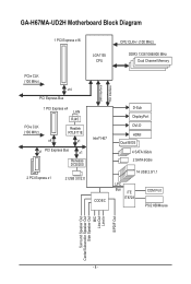
GA-H67MA-UD2H Motherboard Block Diagram 1 PCI Express x16 LGA1155 CPU CPU CLK+/- (100 MHz) DDR3 1333/1066/800 MHz Dual Channel Memory PCIe CLK (100 MHz) x16 PCI ...
GA-H67MA-UD2H Motherboard Block Diagram 1 PCI Express x16 LGA1155 CPU CPU CLK+/- (100 MHz) DDR3 1333/1066/800 MHz Dual Channel Memory PCIe CLK (100 MHz) x16 PCI ...

Manual
Page 9
...internal connectors on the computer power during the installation process can become damaged as a motherboard, CPU or memory. Hardware Installation Chapter 1 Hardware Installation 1-1 Installation Precautions The motherboard contains numerous delicate electronic circuits and components which can lead to damage to system ... ESD wrist strap, keep your hands dry and first touch a metal object to eliminate static electricity. • Prior to installing the motherboard, please have a problem related to the use of the product, please consult a certified computer technician. - 9 - If you are...
...internal connectors on the computer power during the installation process can become damaged as a motherboard, CPU or memory. Hardware Installation Chapter 1 Hardware Installation 1-1 Installation Precautions The motherboard contains numerous delicate electronic circuits and components which can lead to damage to system ... ESD wrist strap, keep your hands dry and first touch a metal object to eliminate static electricity. • Prior to installing the motherboard, please have a problem related to the use of the product, please consult a certified computer technician. - 9 - If you are...
Manual
Page 12
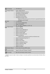
... for Cloud OC Support for Q-Share Bundled Software w Norton Internet Security (OEM version) Operating System w Support for EasyTune * Available functions in EasyTune may differ by motherboard model. I/O Controller w iTE IT8728 chip Hardware Monitor w w w w w w BIOS w w w w Unique Features w w w w w w w w ...XP Form Factor w Micro ATX Form Factor; 24.4cm x 24.4cm * GIGABYTE reserves the right to make any changes to the product specifications and product-related information without prior notice....
... for Cloud OC Support for Q-Share Bundled Software w Norton Internet Security (OEM version) Operating System w Support for EasyTune * Available functions in EasyTune may differ by motherboard model. I/O Controller w iTE IT8728 chip Hardware Monitor w w w w w w BIOS w w w w Unique Features w w w w w w w w ...XP Form Factor w Micro ATX Form Factor; 24.4cm x 24.4cm * GIGABYTE reserves the right to make any changes to the product specifications and product-related information without prior notice....
Manual
Page 13
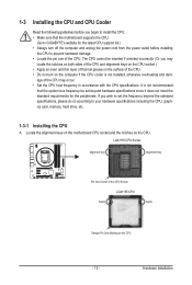
...(Or you wish to set beyond the standard specifications, please do so according to GIGABYTE's website for the peripherals. It is not installed, otherwise overheating and dam- Locate the alignment keys on the motherboard CPU socket and the notches on the surface of the CPU. The CPU cannot ... age of the CPU Socket LGA1155 CPU Notch Notch Triangle Pin One Marking on the computer if the CPU cooler is not recommended that the motherboard supports the CPU. (Go to your hardware specifications including the CPU, graphics card, memory, hard drive, etc. 1-3-1 Installing the CPU A....
...(Or you wish to set beyond the standard specifications, please do so according to GIGABYTE's website for the peripherals. It is not installed, otherwise overheating and dam- Locate the alignment keys on the motherboard CPU socket and the notches on the surface of the CPU. The CPU cannot ... age of the CPU Socket LGA1155 CPU Notch Notch Triangle Pin One Marking on the computer if the CPU cooler is not recommended that the motherboard supports the CPU. (Go to your hardware specifications including the CPU, graphics card, memory, hard drive, etc. 1-3-1 Installing the CPU A....

Manual
Page 14
... CPU socket, always replace the protective socket cover when the CPU is under the shoulder screw. Step 5: Push the CPU socket lever back into the motherboard CPU socket. NOTE: Hold the CPU socket lever by the handle, not the lever base portion. Before installing the CPU, make sure the front end...
... CPU socket, always replace the protective socket cover when the CPU is under the shoulder screw. Step 5: Push the CPU socket lever back into the motherboard CPU socket. NOTE: Hold the CPU socket lever by the handle, not the lever base portion. Before installing the CPU, make sure the front end...

Manual
Page 15
... power connector of the CPU cooler to the CPU fan header (CPU_FAN) on installing the cooler.) Step 5: After the installation, check the back of the motherboard. Check that the Male and Female push pins are joined closely. (Refer to your CPU cooler installation manual for instructions on the... motherboard. If the push pin is inserted as the example cooler.) Direction of the Arrow Sign on the Male Push Pin Male Push Pin The Top ...
... power connector of the CPU cooler to the CPU fan header (CPU_FAN) on installing the cooler.) Step 5: After the installation, check the back of the motherboard. Check that the Male and Female push pins are joined closely. (Refer to your CPU cooler installation manual for instructions on the... motherboard. If the push pin is inserted as the example cooler.) Direction of the Arrow Sign on the Male Push Pin Male Push Pin The Top ...
Manual
Page 16
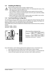
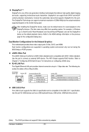
...two memory sockets as following guidelines before installing the memory to insert the memory, switch the direction. Dual Channel Memory Configuration This motherboard provides four DDR3 memory sockets and supports Dual Channel Technology. When enabling Dual Channel mode with two or four memory modules, it...Due to install the memory: • Make sure that memory of the same capacity, brand, speed, and chips be used . (Go to GIGABYTE's website for optimum performance. It is recommended that memory of the memory. If you begin to CPU limitations, read the following : Channel 0: ...
...two memory sockets as following guidelines before installing the memory to insert the memory, switch the direction. Dual Channel Memory Configuration This motherboard provides four DDR3 memory sockets and supports Dual Channel Technology. When enabling Dual Channel mode with two or four memory modules, it...Due to install the memory: • Make sure that memory of the same capacity, brand, speed, and chips be used . (Go to GIGABYTE's website for optimum performance. It is recommended that memory of the memory. If you begin to CPU limitations, read the following : Channel 0: ...

Manual
Page 17
... down on the socket. DDR3 and DDR2 DIMMs are not compatible to each other or DDR DIMMs. Be sure to install DDR3 DIMMs on this motherboard.
... down on the socket. DDR3 and DDR2 DIMMs are not compatible to each other or DDR DIMMs. Be sure to install DDR3 DIMMs on this motherboard.
Manual
Page 18
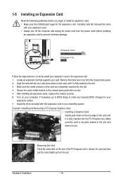
... with your expansion card(s). 7. Remove the metal slot cover from the power outlet before you begin to install an expansion card: • Make sure the motherboard supports the expansion card. If necessary, go to BIOS Setup to make any required BIOS changes for your expansion card. • Always turn off the...
... with your expansion card(s). 7. Remove the metal slot cover from the power outlet before you begin to install an expansion card: • Make sure the motherboard supports the expansion card. If necessary, go to BIOS Setup to make any required BIOS changes for your expansion card. • Always turn off the...
Manual
Page 20
... is compatible with SATA 1.5Gb/s standard. Dual monitor configurations are supported in Windows 7, go to Chapter 5, "Configuring SATA Hard Drive(s)," for the Onboard Graphics: This motherboard provides three video output ports: D-Sub, DVI-D, and HDMI. Connection/ Speed LED Activity LED LAN Port Connection/Speed LED: State Description Orange 1 Gbps data rate...
... is compatible with SATA 1.5Gb/s standard. Dual monitor configurations are supported in Windows 7, go to Chapter 5, "Configuring SATA Hard Drive(s)," for the Onboard Graphics: This motherboard provides three video output ports: D-Sub, DVI-D, and HDMI. Connection/ Speed LED Activity LED LAN Port Connection/Speed LED: State Description Orange 1 Gbps data rate...

Manual
Page 21
... 2/4/5.1/7.1-Channel Audio." • When removing the cable connected to a back panel connector, first remove the cable from your device and then remove it from the motherboard. • When removing the cable, pull it side to side to prevent an electrical short inside the cable connector. - 21 - Line In Jack (Blue) The...
... 2/4/5.1/7.1-Channel Audio." • When removing the cable connected to a back panel connector, first remove the cable from your device and then remove it from the motherboard. • When removing the cable, pull it side to side to prevent an electrical short inside the cable connector. - 21 - Line In Jack (Blue) The...

Manual
Page 22
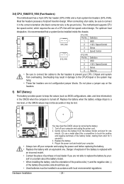
... 3) CPU_FAN 4) SYS_FAN 5) BAT 6) SATA3_0/1 7) SATA2_2/3/4 8) F_PANEL 9) F_AUDIO 10) SPDIF_O 11) F_USB1/2/3/4/5 12) COM 13) CLR_CMOS 14) PHASE_LED Read the following guidelines before turning on the motherboard.
... 3) CPU_FAN 4) SYS_FAN 5) BAT 6) SATA3_0/1 7) SATA2_2/3/4 8) F_PANEL 9) F_AUDIO 10) SPDIF_O 11) F_USB1/2/3/4/5 12) COM 13) CLR_CMOS 14) PHASE_LED Read the following guidelines before turning on the motherboard.

Manual
Page 23
... system. 8 4 5 1 ATX_12V_2X4 ATX_12V_2X4: Pin No. The power connector possesses a foolproof design. To meet expansion requirements, it is turned off and all the components on the motherboard. If the 12V power connector is used (500W or greater). If a power supply is not connected, the computer will not start.
... system. 8 4 5 1 ATX_12V_2X4 ATX_12V_2X4: Pin No. The power connector possesses a foolproof design. To meet expansion requirements, it is turned off and all the components on the motherboard. If the 12V power connector is used (500W or greater). If a power supply is not connected, the computer will not start.
Manual
Page 24
3/4) CPU_FAN/SYS_FAN (Fan Headers) The motherboard has a 4-pin CPU fan header (CPU_FAN) and a 4-pin system fan headers (SYS_FAN). Overheating may result in damage to a low level, or the CMOS values may ..., making them short for one . You may hang. • These fan headers are not able to prevent your computer and unplug the power cord. 2. The motherboard supports CPU fan speed control, which requires the use a metal object like a screwdriver to touch the positive and negative terminals of purchase or local dealer...
3/4) CPU_FAN/SYS_FAN (Fan Headers) The motherboard has a 4-pin CPU fan header (CPU_FAN) and a 4-pin system fan headers (SYS_FAN). Overheating may result in damage to a low level, or the CMOS values may ..., making them short for one . You may hang. • These fan headers are not able to prevent your computer and unplug the power cord. 2. The motherboard supports CPU fan speed control, which requires the use a metal object like a screwdriver to touch the positive and negative terminals of purchase or local dealer...


