Manual
Page 2
Motherboard GA-G41MT-S2PT Jul. 22, 2011 Motherboard GA-G41MT-S2PT Jul. 22, 2011
Motherboard GA-G41MT-S2PT Jul. 22, 2011 Motherboard GA-G41MT-S2PT Jul. 22, 2011
Manual
Page 3
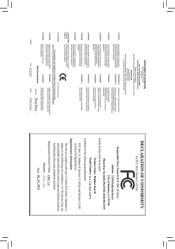
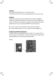
...order to their respective owners. For example, "REV: 1.0" means the revision of GIGABYTE. Check your motherboard looks like this manual is protected by copyright laws and is the property of the motherboard is 1.0. Changes to the specifications and features in this : "REV: X.X." No ... User's Manual. For product-related information, check on our website at: http://www.gigabyte.com Identifying Your Motherboard Revision The revision number on your motherboard revision before updating motherboard BIOS, drivers, or when looking for technical information. All rights reserved.
...order to their respective owners. For example, "REV: 1.0" means the revision of GIGABYTE. Check your motherboard looks like this manual is protected by copyright laws and is the property of the motherboard is 1.0. Changes to the specifications and features in this : "REV: X.X." No ... User's Manual. For product-related information, check on our website at: http://www.gigabyte.com Identifying Your Motherboard Revision The revision number on your motherboard revision before updating motherboard BIOS, drivers, or when looking for technical information. All rights reserved.
Manual
Page 4
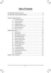
Table of Contents GA-G41MT-S2PT Motherboard Layout 5 GA-G41MT-S2PT Motherboard Block Diagram 6 Chapter 1 Hardware Installation 7 1-1 Installation Precautions 7 1-2 Product Specifications 8 1-3 Installing the CPU 10 1-4 Installing the Memory 11 1-5 Installing an Expansion Card 11 1-6 Back Panel Connectors ...
Table of Contents GA-G41MT-S2PT Motherboard Layout 5 GA-G41MT-S2PT Motherboard Block Diagram 6 Chapter 1 Hardware Installation 7 1-1 Installation Precautions 7 1-2 Product Specifications 8 1-3 Installing the CPU 10 1-4 Installing the Memory 11 1-5 Installing an Expansion Card 11 1-6 Back Panel Connectors ...
Manual
Page 5
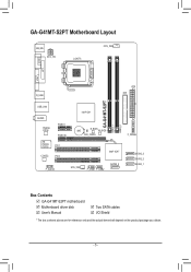
GA-G41MT-S2PT Motherboard Layout KB_MS ATX_12V LGA775 CPU_FAN VGA COM LPT GA-G41MT-S2PT DDR3_1 DDR3_2 R_USB ATX IDE USB_LAN AUDIO Realtek 8111E iTE IT8720/ IT8718 PCIEX1 PCIEX16 PCI1 CODEC PCI2 Intel® G41 BAT B_BIOS M_BIOS CLR_CMOS Intel® ICH7 F_AUDIO SYS_FAN F_USB1 F_USB2 SATA2_0 F_PANEL SATA2_3 SATA2_2 SATA2_1 Box Contents GA-G41MT-S2PT motherboard Motherboard driver disk User's Manual Two SATA cables I/O Shield * The box contents above are for reference only and the actual items shall depend on the product package you obtain. - 5 -
GA-G41MT-S2PT Motherboard Layout KB_MS ATX_12V LGA775 CPU_FAN VGA COM LPT GA-G41MT-S2PT DDR3_1 DDR3_2 R_USB ATX IDE USB_LAN AUDIO Realtek 8111E iTE IT8720/ IT8718 PCIEX1 PCIEX16 PCI1 CODEC PCI2 Intel® G41 BAT B_BIOS M_BIOS CLR_CMOS Intel® ICH7 F_AUDIO SYS_FAN F_USB1 F_USB2 SATA2_0 F_PANEL SATA2_3 SATA2_2 SATA2_1 Box Contents GA-G41MT-S2PT motherboard Motherboard driver disk User's Manual Two SATA cables I/O Shield * The box contents above are for reference only and the actual items shall depend on the product package you obtain. - 5 -
Manual
Page 6
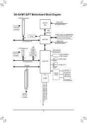
GA-G41MT-S2PT Motherboard Block Diagram 1 PCI Express x16 PCIe CLK (100 MHz) D-Sub x16 PCI Express x16 LGA775 CPU CPU CLK+/(333/266/200 MHz) Host Interface Intel&#...
GA-G41MT-S2PT Motherboard Block Diagram 1 PCI Express x16 PCIe CLK (100 MHz) D-Sub x16 PCI Express x16 LGA775 CPU CPU CLK+/(333/266/200 MHz) Host Interface Intel&#...
Manual
Page 7
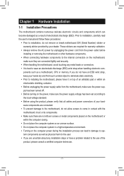
...remove the AC power by your hands dry and first touch a metal object to eliminate static electricity. •• Prior to installing the motherboard, please have it on top of an antistatic pad or within the computer casing. •• Do not place the computer system on an...) wrist strap when handling electronic com- ponents such as a result of your hardware components are connected. •• To prevent damage to the motherboard, do not allow screws to come in a high-temperature environment. •• Turning on the power, make sure they are uncertain about any ...
...remove the AC power by your hands dry and first touch a metal object to eliminate static electricity. •• Prior to installing the motherboard, please have it on top of an antistatic pad or within the computer casing. •• Do not place the computer system on an...) wrist strap when handling electronic com- ponents such as a result of your hardware components are connected. •• To prevent damage to the motherboard, do not allow screws to come in a high-temperature environment. •• Turning on the power, make sure they are uncertain about any ...
Manual
Page 9
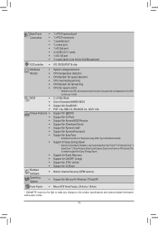
... Xpress Recovery2 ŠŠ Support for EasyTune * Available functions in EasyTune may differ by motherboard model. ŠŠ Support for Microsoft® Windows 7/Vista/XP Form Factor ŠŠ Micro ATX Form Factor; 24.4cm x 19.4cm * GIGABYTE reserves the right to make any changes to the hardware limitation, you install. Back...
... Xpress Recovery2 ŠŠ Support for EasyTune * Available functions in EasyTune may differ by motherboard model. ŠŠ Support for Microsoft® Windows 7/Vista/XP Form Factor ŠŠ Micro ATX Form Factor; 24.4cm x 19.4cm * GIGABYTE reserves the right to make any changes to the hardware limitation, you install. Back...
Manual
Page 10
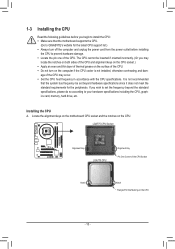
... CPU host frequency in accordance with the CPU specifications. Locate the alignment keys on the motherboard CPU socket and the notches on the CPU - 10 - It is not recommended that the motherboard supports the CPU. (Go to GIGABYTE's website for the latest CPU support list.) •• Always turn on the computer if...
... CPU host frequency in accordance with the CPU specifications. Locate the alignment keys on the motherboard CPU socket and the notches on the CPU - 10 - It is not recommended that the motherboard supports the CPU. (Go to GIGABYTE's website for the latest CPU support list.) •• Always turn on the computer if...
Manual
Page 11
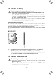
... Technology. The two DDR3 memory sockets are unable to insert the memory, switch the direction. It is recommended that the motherboard supports the memory. Enabling Dual Channel memory mode will automatically detect the specifications and capacity of the same capacity, brand, speed...the following guidelines before you begin to install an expansion card: •• Make sure the motherboard supports the expansion card. A memory module can be used . (Go to GIGABYTE's website for optimum performance. 1-5 Installing an Expansion Card Read the following guidelines before you begin ...
... Technology. The two DDR3 memory sockets are unable to insert the memory, switch the direction. It is recommended that the motherboard supports the memory. Enabling Dual Channel memory mode will automatically detect the specifications and capacity of the same capacity, brand, speed...the following guidelines before you begin to install an expansion card: •• Make sure the motherboard supports the expansion card. A memory module can be used . (Go to GIGABYTE's website for optimum performance. 1-5 Installing an Expansion Card Read the following guidelines before you begin ...
Manual
Page 12
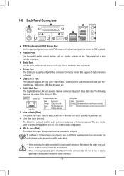
... Ethernet LAN port provides Internet connection at up to a back panel connector, first remove the cable from your device and then remove it from the motherboard. •• When removing the cable, pull it side to side to connect front speakers in devices such as a USB keyboard/mouse, USB printer, USB...
... Ethernet LAN port provides Internet connection at up to a back panel connector, first remove the cable from your device and then remove it from the motherboard. •• When removing the cable, pull it side to side to connect front speakers in devices such as a USB keyboard/mouse, USB printer, USB...
Manual
Page 13
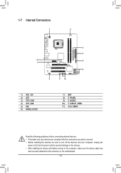
... Connectors 1 3 5 2 11 8 7 6 9 4 10 1) ATX_12V 2) ATX 3) CPU_FAN 4) SYS_FAN 5) IDE 6) SATA2_0/1/2/3 7) BAT 8) F_PANEL 9) F_AUDIO 10) F_USB1/F_USB2 11) CLR_CMOS Read the following guidelines before turning on the motherboard. - 13 -
... Connectors 1 3 5 2 11 8 7 6 9 4 10 1) ATX_12V 2) ATX 3) CPU_FAN 4) SYS_FAN 5) IDE 6) SATA2_0/1/2/3 7) BAT 8) F_PANEL 9) F_AUDIO 10) F_USB1/F_USB2 11) CLR_CMOS Read the following guidelines before turning on the motherboard. - 13 -
Manual
Page 14
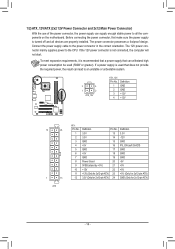
... the power supply is not connected, the computer will not start. If the 12V power connector is turned off and all the components on the motherboard. Connect the power supply cable to an unstable or unbootable system. 3 4 1 2 ATX_12V ATX_12V: Pin No. 1 2 3 4 Definition GND GND +12V +12V 12 24 1 13 ATX ATX...
... the power supply is not connected, the computer will not start. If the 12V power connector is turned off and all the components on the motherboard. Connect the power supply cable to an unstable or unbootable system. 3 4 1 2 ATX_12V ATX_12V: Pin No. 1 2 3 4 Definition GND GND +12V +12V 12 24 1 13 ATX ATX...
Manual
Page 15
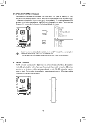
... connector supports up to prevent your CPU and system from the device manufacturers.) 40 39 2 1 - 15 - Do not place a jumper cap on the connector. The motherboard supports CPU fan speed control, which requires the use of the IDE devices (for example, master or slave). (For information about configuring master/slave settings... sure to connect fan cables to the fan headers to two IDE devices such as hard drives and optical drives. 3/4) CPU_FAN/SYS_FAN (Fan Headers) The motherboard has a 4-pin CPU fan header (CPU_FAN) and a 3-pin system fan header (SYS_FAN).
... connector supports up to prevent your CPU and system from the device manufacturers.) 40 39 2 1 - 15 - Do not place a jumper cap on the connector. The motherboard supports CPU fan speed control, which requires the use of the IDE devices (for example, master or slave). (For information about configuring master/slave settings... sure to connect fan cables to the fan headers to two IDE devices such as hard drives and optical drives. 3/4) CPU_FAN/SYS_FAN (Fan Headers) The motherboard has a 4-pin CPU fan header (CPU_FAN) and a 3-pin system fan header (SYS_FAN).
Manual
Page 18
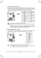
... audio header supports Intel High Definition audio (HD) and AC'97 audio. Incorrect connection between the module connector and the motherboard header will be sure to turn off your chassis front panel audio module to this header. Each USB header can provide two... contact the chassis manufacturer. 10) F_USB1/F_USB2 (USB 2.0/1.1 Headers) The headers conform to installing the USB bracket, be present on each wire instead of the motherboard header. Definition Pin No. For purchasing the optional USB bracket, please contact the local dealer. 9 1 10 2 Pin No. 1 2 3 4 5 6 7 8 9 ...
... audio header supports Intel High Definition audio (HD) and AC'97 audio. Incorrect connection between the module connector and the motherboard header will be sure to turn off your chassis front panel audio module to this header. Each USB header can provide two... contact the chassis manufacturer. 10) F_USB1/F_USB2 (USB 2.0/1.1 Headers) The headers conform to installing the USB bracket, be present on each wire instead of the motherboard header. Definition Pin No. For purchasing the optional USB bracket, please contact the local dealer. 9 1 10 2 Pin No. 1 2 3 4 5 6 7 8 9 ...
Manual
Page 19
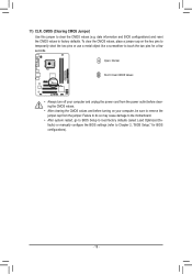
... defaults. 11) CLR_CMOS (Clearing CMOS Jumper) Use this jumper to Chapter 2, "BIOS Setup," for a few seconds. Failure to do so may cause damage to the motherboard. •• After system restart, go to BIOS Setup to load factory defaults (select Load Optimized Defaults) or manually configure the BIOS settings (refer to...
... defaults. 11) CLR_CMOS (Clearing CMOS Jumper) Use this jumper to Chapter 2, "BIOS Setup," for a few seconds. Failure to do so may cause damage to the motherboard. •• After system restart, go to BIOS Setup to load factory defaults (select Load Optimized Defaults) or manually configure the BIOS settings (refer to...
Manual
Page 20
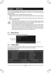
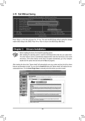
To upgrade the BIOS, use either the GIGABYTE Q-Flash or @BIOS utility. •• Q-Flash allows the...Inadequate BIOS flashing may appear when the computer boots. Inadequately altering the settings may result in Chapter 1 for how to boot. G41MT-S2PT E13 . . . . : BIOS Setup : XpressRecovery2 : Boot Menu : Qflash 07/04/2011-G41-6A79PG0RC-00 Function Keys ... is recommended that you enter the BIOS Setup program, the Main Menu (as shown below) appears on . Motherboard Model BIOS Version Award Modular BIOS v6.00PG Copyright (C) 1984-2011, Award Software, Inc. To flash the ...
To upgrade the BIOS, use either the GIGABYTE Q-Flash or @BIOS utility. •• Q-Flash allows the...Inadequate BIOS flashing may appear when the computer boots. Inadequately altering the settings may result in Chapter 1 for how to boot. G41MT-S2PT E13 . . . . : BIOS Setup : XpressRecovery2 : Boot Menu : Qflash 07/04/2011-G41-6A79PG0RC-00 Function Keys ... is recommended that you enter the BIOS Setup program, the Main Menu (as shown below) appears on . Motherboard Model BIOS Version Award Modular BIOS v6.00PG Copyright (C) 1984-2011, Award Software, Inc. To flash the ...
Manual
Page 30
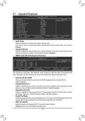
...; Move Enter: Select F5: Previous Values +/-/PU/PD: Value F10: Save F6: Fail-Safe Defaults ESC: Exit F1: General Help F7: Optimized Defaults This motherboard incorporates cable diagnostic feature designed to detect the status of the attached LAN cable. Options are : SPP (Standard Parallel Port) (default), EPP (Enhanced Parallel Port...
...; Move Enter: Select F5: Previous Values +/-/PU/PD: Value F10: Save F6: Fail-Safe Defaults ESC: Exit F1: General Help F7: Optimized Defaults This motherboard incorporates cable diagnostic feature designed to detect the status of the attached LAN cable. Options are : SPP (Standard Parallel Port) (default), EPP (Enhanced Parallel Port...
Manual
Page 33
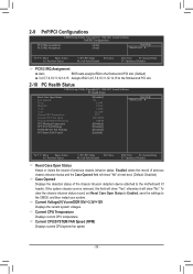
... current CPU/system fan speed. - 33 - To clear the chassis intrusion status record, set Reset Case Open Status to Enabled, save the settings to the motherboard CI header. If the system chassis cover is removed, this field will show "Yes", otherwise it will show "No". Current CPU Temperature Displays current CPU...
... current CPU/system fan speed. - 33 - To clear the chassis intrusion status record, set Reset Case Open Status to Enabled, save the settings to the motherboard CI header. If the system chassis cover is removed, this field will show "Yes", otherwise it will show "No". Current CPU Temperature Displays current CPU...
Manual
Page 34
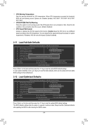
CPU Warning Temperature Sets the warning threshold for the motherboard. 2-12 Load Optimized Defaults CMOS Setup Utility-Copyright (C) 1984-2011 Award Software MB Intelligent Tweaker(M.I .T.) PC Health Status Standard CMOS Features Load ...
CPU Warning Temperature Sets the warning threshold for the motherboard. 2-12 Load Optimized Defaults CMOS Setup Utility-Copyright (C) 1984-2011 Award Software MB Intelligent Tweaker(M.I .T.) PC Health Status Standard CMOS Features Load ...
Manual
Page 36
... optical drive. Chapter 3 Drivers Installation •• Before installing the drivers, first install the operating system. •• After installing the operating system, insert the motherboard driver disk into your system and then list all Data F11: Save CMOS to BIOS F12: Load CMOS from BIOS Press on this item and...
... optical drive. Chapter 3 Drivers Installation •• Before installing the drivers, first install the operating system. •• After installing the operating system, insert the motherboard driver disk into your system and then list all Data F11: Save CMOS to BIOS F12: Load CMOS from BIOS Press on this item and...


