

Manual
Page 5
... ...7 Box Contents ...7 GA-G33M-DS2R/S2 Motherboard Layout 8 Block Diagram ...9 Chapter 1 Hardware Installation 11 1-1 Installation Precautions 11 1-2 Product Specifications 12 1-3 Installing the CPU and CPU Cooler 15 1-3-1 Installing the CPU 15 1-3-2 Installing the CPU Cooler 17 1-4 Installing the Memory 18 1-4-1 Dual Channel Memory Configuration 18 1-4-2 Installing a Memory 19 1-5 Installing an Expansion Card 20 1-6 Back Panel Connectors 21 1-7 Internal Connectors 23 Chapter 2 BIOS Setup 35 2-1 Startup Screen 36 2-2 The Main Menu 37 2-3 Standard CMOS Features 39 2-4 Advanced...
... ...7 Box Contents ...7 GA-G33M-DS2R/S2 Motherboard Layout 8 Block Diagram ...9 Chapter 1 Hardware Installation 11 1-1 Installation Precautions 11 1-2 Product Specifications 12 1-3 Installing the CPU and CPU Cooler 15 1-3-1 Installing the CPU 15 1-3-2 Installing the CPU Cooler 17 1-4 Installing the Memory 18 1-4-1 Dual Channel Memory Configuration 18 1-4-2 Installing a Memory 19 1-5 Installing an Expansion Card 20 1-6 Back Panel Connectors 21 1-7 Internal Connectors 23 Chapter 2 BIOS Setup 35 2-1 Startup Screen 36 2-2 The Main Menu 37 2-3 Standard CMOS Features 39 2-4 Advanced...
Manual
Page 12
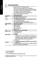
.... Support for SATA RAID 0, RAID 1, RAID 5, and RAID 10 Š JMicron 368 chip: - 1 x IDE connector supporting ATA-133/100/66/33 and up to 4 SATA 3Gb/s devices(Note 2) - GA-G33M-DS2R/S2 Motherboard - 12 - TSB43AB23 chip Š Up to 3 IEEE 1394a ports (1 on the back panel, 2 via the IEEE 1394 bracket connected to 2 IDE devices Š T.I. English 1-2 Product Specifications CPU Front Side Bus Chipset Memory Onboard Graphics Audio LAN Expansion Slots Storage Interface IEEE 1394 Š Support for an Intel® CoreTM 2 Extreme processor/ Intel...
.... Support for SATA RAID 0, RAID 1, RAID 5, and RAID 10 Š JMicron 368 chip: - 1 x IDE connector supporting ATA-133/100/66/33 and up to 4 SATA 3Gb/s devices(Note 2) - GA-G33M-DS2R/S2 Motherboard - 12 - TSB43AB23 chip Š Up to 3 IEEE 1394a ports (1 on the back panel, 2 via the IEEE 1394 bracket connected to 2 IDE devices Š T.I. English 1-2 Product Specifications CPU Front Side Bus Chipset Memory Onboard Graphics Audio LAN Expansion Slots Storage Interface IEEE 1394 Š Support for an Intel® CoreTM 2 Extreme processor/ Intel...

Manual
Page 14
... enable hot plug capability for the SATA connectors (SATAII0, SATAII1, SATAII4, SATAII5) controlled by the ICH9 South Bridge, you must install Windows Vista (on ICH9, hot plug is supported in Windows Vista only) and configure the SATA connectors for AHCI mode. (Refer to Chapter 2, "BIOS Setup," "Integrated Peripherals," for details on enabling AHCI.) (Note 3) Available functions in Easytune may differ by motherboard model. (Note 4) Due to chipset limitation, Intel ICH9R RAID driver does not support Windows...
... enable hot plug capability for the SATA connectors (SATAII0, SATAII1, SATAII4, SATAII5) controlled by the ICH9 South Bridge, you must install Windows Vista (on ICH9, hot plug is supported in Windows Vista only) and configure the SATA connectors for AHCI mode. (Refer to Chapter 2, "BIOS Setup," "Integrated Peripherals," for details on enabling AHCI.) (Note 3) Available functions in Easytune may differ by motherboard model. (Note 4) Due to chipset limitation, Intel ICH9R RAID driver does not support Windows...

Manual
Page 18
...; Flex Memory Technology offers greater flexibility to upgrade by allowing different memory sizes to chipset limitation, read the following guidelines before installing the memory in only one DDR2 memory module is installed, the BIOS will double the original memory bandwidth. GA-G33M-DS2R/S2 Motherboard - 18 - Enabling Dual Channel memory mode will automatically detect the specifications and capacity of different capacity and chips are divided into two channels and each channel has two memory sockets as following: Channel...
...; Flex Memory Technology offers greater flexibility to upgrade by allowing different memory sizes to chipset limitation, read the following guidelines before installing the memory in only one DDR2 memory module is installed, the BIOS will double the original memory bandwidth. GA-G33M-DS2R/S2 Motherboard - 18 - Enabling Dual Channel memory mode will automatically detect the specifications and capacity of different capacity and chips are divided into two channels and each channel has two memory sockets as following: Channel...
Manual
Page 20
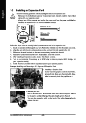
... the PCI Express x16 slot. Locate an expansion slot that came with the expansion card in the expansion slot. 1. Secure the card's metal bracket to the chassis back panel with the slot, and press down on your operating system. Install the driver provided with your expansion card. • Always turn off the computer and unplug the power cord from the chassis back panel. 2. GA-G33M-DS2R/S2 Motherboard - 20 - Remove the metal slot cover...
... the PCI Express x16 slot. Locate an expansion slot that came with the expansion card in the expansion slot. 1. Secure the card's metal bracket to the chassis back panel with the slot, and press down on your operating system. Install the driver provided with your expansion card. • Always turn off the computer and unplug the power cord from the chassis back panel. 2. GA-G33M-DS2R/S2 Motherboard - 20 - Remove the metal slot cover...

Manual
Page 25
... Installation The motherboard supports CPU fan speed control, which requires the use of floppy disk drives supported are not configuration jumper blocks. Before connecting a floppy disk drive, locate the foolproof groove on the headers. 5) FDD (Floppy Disk Drive Connector) This connector is used to prevent your CPU and system from overheating. Each fan header supplies a +12V power voltage and possesses a foolproof insertion design. CPU_FAN 1 1 SYS_FAN Pin No. 1 2 3 4 Definition GND +12V / Speed Control Sense Speed Control • Be sure to connect fan cables to the fan headers...
... Installation The motherboard supports CPU fan speed control, which requires the use of floppy disk drives supported are not configuration jumper blocks. Before connecting a floppy disk drive, locate the foolproof groove on the headers. 5) FDD (Floppy Disk Drive Connector) This connector is used to prevent your CPU and system from overheating. Each fan header supplies a +12V power voltage and possesses a foolproof insertion design. CPU_FAN 1 1 SYS_FAN Pin No. 1 2 3 4 Definition GND +12V / Speed Control Sense Speed Control • Be sure to connect fan cables to the fan headers...

Manual
Page 31
... motherboard driver disk and your operating system has been updated with the latest Service Pack for Windows before installing the graphics card driver. - 31 - For purchasing the optional S/PDIF in and out cable, please contact the local dealer. 26 15 Pin No. 1 2 3 4 5 6 Definition Power No Pin SPDIF SPDIFI GND GND 14) HDMI_AC (HDMI Adapter Audio Cable Connector) When the HDMI adapter is installed in . Hardware Installation English 13) SPDIF_IO (S/PDIF In/Out Header) This header supports...
... motherboard driver disk and your operating system has been updated with the latest Service Pack for Windows before installing the graphics card driver. - 31 - For purchasing the optional S/PDIF in and out cable, please contact the local dealer. 26 15 Pin No. 1 2 3 4 5 6 Definition Power No Pin SPDIF SPDIFI GND GND 14) HDMI_AC (HDMI Adapter Audio Cable Connector) When the HDMI adapter is installed in . Hardware Installation English 13) SPDIF_IO (S/PDIF In/Out Header) This header supports...
Manual
Page 38
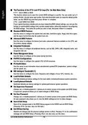
..., hard drive types, floppy disk drive types, and the type of errors that stop the system boot, etc. „ Advanced BIOS Features Use this menu to configure the device boot order, advanced features available on the CPU, and the primary display adapter. „ Integrated Peripherals Use this menu to configure all peripheral devices, such as IDE, SATA, USB, integrated audio, and integrated LAN, etc. „ Power Management Setup Use this menu to configure all changes and the previous settings remain in BIOS Setup. „ Set User Password Change, set , or disable password. An user password...
..., hard drive types, floppy disk drive types, and the type of errors that stop the system boot, etc. „ Advanced BIOS Features Use this menu to configure the device boot order, advanced features available on the CPU, and the primary display adapter. „ Integrated Peripherals Use this menu to configure all peripheral devices, such as IDE, SATA, USB, integrated audio, and integrated LAN, etc. „ Power Management Setup Use this menu to configure all changes and the previous settings remain in BIOS Setup. „ Set User Password Change, set , or disable password. An user password...

Manual
Page 41
... Technology. Setup A password is only required for entering the BIOS Setup program. (Default) System A password is required for booting the system and for operating systems that supports this feature. HDD S.M.A.R.T. to 3 (Note) No-Execute Memory Protect (Note) CPU Enhanced Halt (C1E) (Note) CPU Thermal Monitor 2(TM2) (Note) CPU EIST Function (Note) Virtualization Technology (Note) Init Display First Onboard VGA On-Chip Frame Buffer Size [Press Enter] [Floppy] [Hard Disk] [CDROM] [Setup] [Disabled] [Enabled] [Disabled] [Enabled] [Enabled] [Enabled] [Enabled] [Enabled] [PCI] [Enable...
... Technology. Setup A password is only required for entering the BIOS Setup program. (Default) System A password is required for booting the system and for operating systems that supports this feature. HDD S.M.A.R.T. to 3 (Note) No-Execute Memory Protect (Note) CPU Enhanced Halt (C1E) (Note) CPU Thermal Monitor 2(TM2) (Note) CPU EIST Function (Note) Virtualization Technology (Note) Init Display First Onboard VGA On-Chip Frame Buffer Size [Press Enter] [Floppy] [Hard Disk] [CDROM] [Setup] [Disabled] [Enabled] [Disabled] [Enabled] [Enabled] [Enabled] [Enabled] [Enabled] [PCI] [Enable...

Manual
Page 42
Depending on CPU loading, Intel® EIST technology can function as multiple virtual systems. (Default: Enabled) Init Display First Specifies the first initiation of the monitor display from the installed PCI graphics card, PCI Express graphics card, or the onboard VGA. PCI Sets the PCI graphics card as the first display. (Default) Onboard Sets the onboard VGA as Windows NT4.0. (Default: Disabled) No-Execute Memory Protect (Note) Enables or disables Intel® Execute Disable Bit function. GA-G33M-DS2R/S2 Motherboard - 42 - Set this item to Disabled for the computer, ...
Depending on CPU loading, Intel® EIST technology can function as multiple virtual systems. (Default: Enabled) Init Display First Specifies the first initiation of the monitor display from the installed PCI graphics card, PCI Express graphics card, or the onboard VGA. PCI Sets the PCI graphics card as the first display. (Default) Onboard Sets the onboard VGA as Windows NT4.0. (Default: Disabled) No-Execute Memory Protect (Note) Enables or disables Intel® Execute Disable Bit function. GA-G33M-DS2R/S2 Motherboard - 42 - Set this item to Disabled for the computer, ...

Manual
Page 43
... buffer size is installed. MS-DOS, for example, will use only this item to set up a dual view configuration, set this memory for display. Options are: 8MB+1~2MB for GTT (default), 1MB+1~2MB for the onboard graphics controller. English Onboard VGA Enables or disables the onboard VGA function. If you wish to Always Enable. BIOS Setup Enable If No Ext PEG Activates the onboard VGA only if no PCI Express VGA card is installed. (Default) Always Enable Always activates the onboard VGA, whether or not a PCI Express card...
... buffer size is installed. MS-DOS, for example, will use only this item to set up a dual view configuration, set this memory for display. Options are: 8MB+1~2MB for GTT (default), 1MB+1~2MB for the onboard graphics controller. English Onboard VGA Enables or disables the onboard VGA function. If you wish to Always Enable. BIOS Setup Enable If No Ext PEG Activates the onboard VGA only if no PCI Express VGA card is installed. (Default) Always Enable Always activates the onboard VGA, whether or not a PCI Express card...

Manual
Page 44
...and hot plug. English 2-5 Integrated Peripherals CMOS Setup Utility-Copyright (C) 1984-2007 Award Software Integrated Peripherals SATA RAID/AHCI Mode 1 SATA AHCI Mode 2 SATA Port0-3 Native Mode USB Controller USB 2.0 Controller USB Keyboard Support USB Mouse Support Legacy USB storage detect Azalia Codec Onboard H/W 1394 Onboard H/W LAN ` SMART LAN OnBoard LAN Boot ROM Onboard IDE Controller Onboard Serial Port 1 Onboard Serial Port 2 Onboard Parallel Port Parallel Port Mode [Disabled] [Disabled] [Disabled] [Enabled] [Enabled] [Disabled] [Disabled] [Enabled] [Auto] [Enabled] [Enabled...
...and hot plug. English 2-5 Integrated Peripherals CMOS Setup Utility-Copyright (C) 1984-2007 Award Software Integrated Peripherals SATA RAID/AHCI Mode 1 SATA AHCI Mode 2 SATA Port0-3 Native Mode USB Controller USB 2.0 Controller USB Keyboard Support USB Mouse Support Legacy USB storage detect Azalia Codec Onboard H/W 1394 Onboard H/W LAN ` SMART LAN OnBoard LAN Boot ROM Onboard IDE Controller Onboard Serial Port 1 Onboard Serial Port 2 Onboard Parallel Port Parallel Port Mode [Disabled] [Disabled] [Disabled] [Enabled] [Enabled] [Disabled] [Disabled] [Enabled] [Auto] [Enabled] [Enabled...

Manual
Page 47
... operating mode for the onboard parallel (LPT) port. Onboard Serial Port 2 Enables or disables the second serial port and specifies its base I /O address and corresponding interrupt. BIOS Setup Options are : Auto, 3F8/IRQ4 (default), 2F8/IRQ3, 3E8/IRQ4, 2E8/IRQ3, Disabled. English Onboard LAN Boot ROM Allows you to decide whether to activate the boot ROM integrated with the onboard LAN chip. (Default: Disabled) Onboard IDE Controller (JMicron 368 Chip) Enables or disables the IDE controller integrated in the JMicron 368 chip. (Default: Enabled) Onboard Serial Port 1 Enables or disables...
... operating mode for the onboard parallel (LPT) port. Onboard Serial Port 2 Enables or disables the second serial port and specifies its base I /O address and corresponding interrupt. BIOS Setup Options are : Auto, 3F8/IRQ4 (default), 2F8/IRQ3, 3E8/IRQ4, 2E8/IRQ3, Disabled. English Onboard LAN Boot ROM Allows you to decide whether to activate the boot ROM integrated with the onboard LAN chip. (Default: Disabled) Onboard IDE Controller (JMicron 368 Chip) Enables or disables the IDE controller integrated in the JMicron 368 chip. (Default: Enabled) Onboard Serial Port 1 Enables or disables...

Manual
Page 52
... full speed. However, for a 3-pin CPU fan or a 4-pin CPU fan. PWM Sets PWM mode for a 3-pin CPU fan. GA-G33M-DS2R/S2 Motherboard - 52 - A small portion of system memory will be controlled by the Intel Quiet System Technology (QST). This feature requires the installation of CPU fan installed and sets the optimal CPU fan control mode. (Default) Voltage Sets Voltage mode for a 4-pin CPU fan. Note: The Voltage mode can be set to run at least DDRII1 or DDRII2 socket in Channel 0 is set for a 4-pin CPU fan that is enabled. Disabled Forces CPU fan to Enabled...
... full speed. However, for a 3-pin CPU fan or a 4-pin CPU fan. PWM Sets PWM mode for a 3-pin CPU fan. GA-G33M-DS2R/S2 Motherboard - 52 - A small portion of system memory will be controlled by the Intel Quiet System Technology (QST). This feature requires the installation of CPU fan installed and sets the optimal CPU fan control mode. (Default) Voltage Sets Voltage mode for a 4-pin CPU fan. Note: The Voltage mode can be set to run at least DDRII1 or DDRII2 socket in Channel 0 is set for a 4-pin CPU fan that is enabled. Disabled Forces CPU fan to Enabled...

Manual
Page 53
... components. mode based on system configurations. The item is present only if a CPU with unlocked clock ratio is recommended that you install a CPU that supports this occurs, clear the CMOS values and reset the board to automatically set the System Voltage Control item to Auto to alter the clock ratio for the installed CPU. Enabled will allow for automated system reboot, or clear the CMOS values to reset the board to default values. (Default: Disabled) (Note...
... components. mode based on system configurations. The item is present only if a CPU with unlocked clock ratio is recommended that you install a CPU that supports this occurs, clear the CMOS values and reset the board to automatically set the System Voltage Control item to Auto to alter the clock ratio for the installed CPU. Enabled will allow for automated system reboot, or clear the CMOS values to reset the board to default values. (Default: Disabled) (Note...
Manual
Page 58
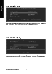
... Saving CMOS Setup Utility-Copyright (C) 1984-2007 Award Software ` Standard CMOS Features Load Fail-Safe Defaults ` Advanced BIOS Features Load Optimized Defaults ` Integrated Peripherals Set Supervisor Password ` Power Management Setup Quit Without Saving (SYe/tNU)?sNer Password ` PnP/PCI Configurations Save & Exit Setup ` PC Health Status Exit Without Saving ` MB Intelligent Tweaker(M.I .T.) ESC: Quit F8: Q-Flash KLJI: Select Item F10: Save & Exit Setup F11: Save CMOS to the CMOS and exits the BIOS Setup program. GA-G33M-DS2R/S2 Motherboard...
... Saving CMOS Setup Utility-Copyright (C) 1984-2007 Award Software ` Standard CMOS Features Load Fail-Safe Defaults ` Advanced BIOS Features Load Optimized Defaults ` Integrated Peripherals Set Supervisor Password ` Power Management Setup Quit Without Saving (SYe/tNU)?sNer Password ` PnP/PCI Configurations Save & Exit Setup ` PC Health Status Exit Without Saving ` MB Intelligent Tweaker(M.I .T.) ESC: Quit F8: Q-Flash KLJI: Select Item F10: Save & Exit Setup F11: Save CMOS to the CMOS and exits the BIOS Setup program. GA-G33M-DS2R/S2 Motherboard...
Manual
Page 75
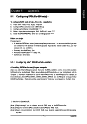
...to "Chapter 1," "Hardware Installation," to identify the SATA controller for GA-G33M-DS2R. (Note 1) Skip this motherboard, the SATAII0, SATAII1, SATAII2, SATAII3, SATAII4 and SATAII5 ports are supported by ICH9R Southbridge.) Then connect the power connector from your computer Attach one hard drive. • An empty formatted floppy disk. • Windows Vista/XP/2000 (Note 3) setup disk. • Motherboard driver disk. 5-1-1 Configuring Intel® ICH9R SATA Controllers A. Appendix Configure SATA controller mode in RAID BIOS. (Note 1) D. Install the SATA RAID/AHCI driver and operating...
...to "Chapter 1," "Hardware Installation," to identify the SATA controller for GA-G33M-DS2R. (Note 1) Skip this motherboard, the SATAII0, SATAII1, SATAII2, SATAII3, SATAII4 and SATAII5 ports are supported by ICH9R Southbridge.) Then connect the power connector from your computer Attach one hard drive. • An empty formatted floppy disk. • Windows Vista/XP/2000 (Note 3) setup disk. • Motherboard driver disk. 5-1-1 Configuring Intel® ICH9R SATA Controllers A. Appendix Configure SATA controller mode in RAID BIOS. (Note 1) D. Install the SATA RAID/AHCI driver and operating...

Manual
Page 76
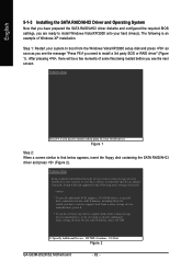
CMOS Setup Utility-Copyright (C) 1984-2007 Award Software Integrated Peripherals SATA RAID/AHCI Mode 1 SATA AHCI Mode 2 SATA Port0-3 Native Mode USB Controller USB 2.0 Controller USB Keyboard Support USB Mouse Support Legacy USB storage detect Azalia Codec Onboard H/W 1394 Onboard H/W LAN ` SMART LAN OnBoard LAN Boot ROM Onboard IDE Controller Onboard Serial Port 1 Onboard Serial Port 2 Onboard Parallel Port Parallel Port Mode [RAID] [Disabled] [Disabled] [Enabled] [Enabled] [Disabled] [Disabled] [Enabled] [Auto] [Enabled] [Enabled] [Press Enter] [Disabled] [Enabled] [3F8/IRQ4] [2F8/IRQ3] ...
CMOS Setup Utility-Copyright (C) 1984-2007 Award Software Integrated Peripherals SATA RAID/AHCI Mode 1 SATA AHCI Mode 2 SATA Port0-3 Native Mode USB Controller USB 2.0 Controller USB Keyboard Support USB Mouse Support Legacy USB storage detect Azalia Codec Onboard H/W 1394 Onboard H/W LAN ` SMART LAN OnBoard LAN Boot ROM Onboard IDE Controller Onboard Serial Port 1 Onboard Serial Port 2 Onboard Parallel Port Parallel Port Mode [RAID] [Disabled] [Disabled] [Enabled] [Enabled] [Disabled] [Disabled] [Enabled] [Auto] [Enabled] [Enabled] [Press Enter] [Disabled] [Enabled] [3F8/IRQ4] [2F8/IRQ3] ...
Manual
Page 82
... RAID driver. S=Specify Additional Device ENTER=Continue F3=Exit Figure 2 GA-G33M-DS2R/S2 Motherboard - 82 - After pressing , there will load support for which you have a device support disk from the Windows Vista/XP/2000 setup disk and press as soon as you see the next screen. Currently, Setup will be a few moments of Windows XP installation. The following mass storage devices(s) * To specify additional SCSI adapters, CD-ROM drives, or special disk controllers for use with Windows...
... RAID driver. S=Specify Additional Device ENTER=Continue F3=Exit Figure 2 GA-G33M-DS2R/S2 Motherboard - 82 - After pressing , there will load support for which you have a device support disk from the Windows Vista/XP/2000 setup disk and press as soon as you see the next screen. Currently, Setup will be a few moments of Windows XP installation. The following mass storage devices(s) * To specify additional SCSI adapters, CD-ROM drives, or special disk controllers for use with Windows...

Manual
Page 92
... possible computer problems. (For reference only.) 1 short: System boots successfully 2 short: CMOS setting error 1 long, 1 short: Memory or motherboard error 1 long, 2 short: Monitor or graphics card error 1 long, 3 short: Keyboard error 1 long, 9 short: BIOS ROM error Continuous long beeps: Graphics card not inserted properly Continuous short beeps: Power error GA-G33M-DS2R/S2 Motherboard - 92 - A: Some motherboard provides a small amount of the battery holder, making them short for 5 seconds.) 3. A: Some advanced options are some BIOS options missing? Plug in Chapter 1.
... possible computer problems. (For reference only.) 1 short: System boots successfully 2 short: CMOS setting error 1 long, 1 short: Memory or motherboard error 1 long, 2 short: Monitor or graphics card error 1 long, 3 short: Keyboard error 1 long, 9 short: BIOS ROM error Continuous long beeps: Graphics card not inserted properly Continuous short beeps: Power error GA-G33M-DS2R/S2 Motherboard - 92 - A: Some motherboard provides a small amount of the battery holder, making them short for 5 seconds.) 3. A: Some advanced options are some BIOS options missing? Plug in Chapter 1.


