
Manual
Page 1
GA-G31M-ES2L/ GA-G31M-ES2C LGA775 socket motherboard for Intel® CoreTM processor family/ Intel® Pentium® processor family/Intel® Celeron® processor family User's Manual Rev. 2301 12ME-G31MES2L-2301R
GA-G31M-ES2L/ GA-G31M-ES2C LGA775 socket motherboard for Intel® CoreTM processor family/ Intel® Pentium® processor family/Intel® Celeron® processor family User's Manual Rev. 2301 12ME-G31MES2L-2301R
Manual
Page 2
Motherboard GA-G31M-ES2L/GA-G31M-ES2C May 20, 2010 Motherboard GA-G31M-ES2L/ GA-G31M-ES2C May 20, 2010
Motherboard GA-G31M-ES2L/GA-G31M-ES2C May 20, 2010 Motherboard GA-G31M-ES2L/ GA-G31M-ES2C May 20, 2010

Manual
Page 3
... features, read the User's Manual. For instructions on how to assist in any form or by GIGABYTE without GIGABYTE's prior written permission. Check your motherboard looks like this product, GIGABYTE provides the following types of this : "REV: X.X." Changes to their respective owners. Copyright © 2010 GIGA-BYTE TECHNOLOGY CO., LTD. Documentation Classifications In...
... features, read the User's Manual. For instructions on how to assist in any form or by GIGABYTE without GIGABYTE's prior written permission. Check your motherboard looks like this product, GIGABYTE provides the following types of this : "REV: X.X." Changes to their respective owners. Copyright © 2010 GIGA-BYTE TECHNOLOGY CO., LTD. Documentation Classifications In...
Manual
Page 4
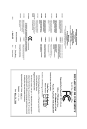
Table of Contents Box Contents ...6 OptionalItems...6 GA-G31M-ES2L/GA-G31M-ES2C Motherboard Layout 7 Block Diagram...8 Chapter 1 Hardware Installation 9 1-1 Installation Precautions 9 1-2 Product Specifications 10 1-3 Installing the CPU and CPU Cooler 13 1-3-1 Installing the CPU 13 1-3-2 Installing the CPU ...
Table of Contents Box Contents ...6 OptionalItems...6 GA-G31M-ES2L/GA-G31M-ES2C Motherboard Layout 7 Block Diagram...8 Chapter 1 Hardware Installation 9 1-1 Installation Precautions 9 1-2 Product Specifications 10 1-3 Installing the CPU and CPU Cooler 13 1-3-1 Installing the CPU 13 1-3-2 Installing the CPU ...
Manual
Page 6
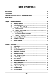
The box contents are for reference only. Optional Items Floppy disk drive cable (Part No. 12CF1-1FD001-7*R) 2-port USB 2.0 bracket (Part No. 12CR1-1UB030-5*R) 2-port SATA power cable (Part No. 12CF1-2SERPW-0*R) S/PDIF out cable (Part No. 12CR1-1SPOUT-0*R) - 6 - Box Contents GA-G31M-ES2L or GA-G31M-ES2C motherboard Motherboard driver disk User's Manual One IDE cable Two SATA cables I/O Shield • The box contents above are subject to change without notice. • The motherboard image is for reference only and the actual items shall depend on product package you obtain.
The box contents are for reference only. Optional Items Floppy disk drive cable (Part No. 12CF1-1FD001-7*R) 2-port USB 2.0 bracket (Part No. 12CR1-1UB030-5*R) 2-port SATA power cable (Part No. 12CF1-2SERPW-0*R) S/PDIF out cable (Part No. 12CR1-1SPOUT-0*R) - 6 - Box Contents GA-G31M-ES2L or GA-G31M-ES2C motherboard Motherboard driver disk User's Manual One IDE cable Two SATA cables I/O Shield • The box contents above are subject to change without notice. • The motherboard image is for reference only and the actual items shall depend on product package you obtain.
Manual
Page 7
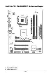
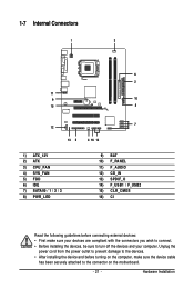
Only for GA-G31M-ES2L. GA-G31M-ES2L/GA-G31M-ES2C Motherboard Layout KB_MS ATX_12V LGA775 CPU_FAN COMA GA-G31M-ES2L/GA-G31M-ES2C DDRII1 DDRII2 PWR_LED F_PANEL LPT LAN VGA R_USB ATX IDE USB AUDIO F_AUDIO AR8131 AR8132 PCIE_1 PCIE_16 IT8718 PCI1 CODEC PCI2 CD_IN SPDIF_O FDD Intel® G31 BAT B_BIOS M_BIOS CLR_CMOS CI SYS_FAN F_USB1F_USB2 Intel® ICH7 SATAII3 SATAII2 SATAII1 SATAII0 Only for GA-G31M-ES2C. - 7 -
Only for GA-G31M-ES2L. GA-G31M-ES2L/GA-G31M-ES2C Motherboard Layout KB_MS ATX_12V LGA775 CPU_FAN COMA GA-G31M-ES2L/GA-G31M-ES2C DDRII1 DDRII2 PWR_LED F_PANEL LPT LAN VGA R_USB ATX IDE USB AUDIO F_AUDIO AR8131 AR8132 PCIE_1 PCIE_16 IT8718 PCI1 CODEC PCI2 CD_IN SPDIF_O FDD Intel® G31 BAT B_BIOS M_BIOS CLR_CMOS CI SYS_FAN F_USB1F_USB2 Intel® ICH7 SATAII3 SATAII2 SATAII1 SATAII0 Only for GA-G31M-ES2C. - 7 -
Manual
Page 9
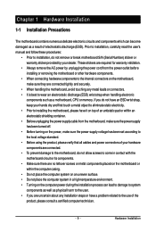
...has been turned off. • Before turning on the power, make sure they are connected tightly and securely. • When handling the motherboard, avoid touching any metal leads or connectors. • It is best to wear an electrostatic discharge (ESD) wrist strap when handling electronic... an electrostatic shielding container. • Before unplugging the power supply cable from the power outlet before installing or removing the motherboard or other hardware components. • When connecting hardware components to the internal connectors on the computer power during the installation ...
...has been turned off. • Before turning on the power, make sure they are connected tightly and securely. • When handling the motherboard, avoid touching any metal leads or connectors. • It is best to wear an electrostatic discharge (ESD) wrist strap when handling electronic... an electrostatic shielding container. • Before unplugging the power supply cable from the power outlet before installing or removing the motherboard or other hardware components. • When connecting hardware components to the internal connectors on the computer power during the installation ...
Manual
Page 10
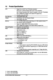
.../ Intel® Pentium® processor/Intel® Celeron® processor in the LGA 775 package (Go to GIGABYTE's website for the latest CPU support list.) L2 cache varies with CPU 1333/1066/800 ...Note 1) Dual channel memory architecture Support for DDR2 800/667 MHz memory modules (Go to GIGABYTE's website for the latest memory support list.) Integrated in the North Bridge Realtek ALC883/888B codec...the USB brackets connected to the internal USB headers) Only for GA-G31M-ES2C. GA-G31M-ES2L/ES2C Motherboard - 10 - Only for GA-G31M-ES2L.
.../ Intel® Pentium® processor/Intel® Celeron® processor in the LGA 775 package (Go to GIGABYTE's website for the latest CPU support list.) L2 cache varies with CPU 1333/1066/800 ...Note 1) Dual channel memory architecture Support for DDR2 800/667 MHz memory modules (Go to GIGABYTE's website for the latest memory support list.) Integrated in the North Bridge Realtek ALC883/888B codec...the USB brackets connected to the internal USB headers) Only for GA-G31M-ES2C. GA-G31M-ES2L/ES2C Motherboard - 10 - Only for GA-G31M-ES2L.
Manual
Page 12
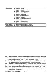
For example, 4 GB of memory size will depend on the CPU you install. (Note 4) Available functions in EasyTune may differ by motherboard model. (Note 5) Due to the hardware limitation, you need connect with the port of memory is less than the stated amount. Unique Features Bundled Software .../ Celeron Dual-Core/ Celeron 400 Series CPU to enable support for system usage and therefore the actual memory size is reserved for Easy Energy Saver. GA-G31M-ES2L/ES2C Motherboard - 12 -
For example, 4 GB of memory size will depend on the CPU you install. (Note 4) Available functions in EasyTune may differ by motherboard model. (Note 5) Due to the hardware limitation, you need connect with the port of memory is less than the stated amount. Unique Features Bundled Software .../ Celeron Dual-Core/ Celeron 400 Series CPU to enable support for system usage and therefore the actual memory size is reserved for Easy Energy Saver. GA-G31M-ES2L/ES2C Motherboard - 12 -
Manual
Page 13
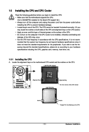
mended that the motherboard supports the CPU. (Go to GIGABYTE's website for the peripherals. Hardware Installation It is not installed, otherwise overheating and damage of the CPU may locate the notches on both sides of ... if oriented incorrectly. (Or you may occur. • Set the CPU host frequency in accordance with the CPU specifications. Locate the alignment keys on the motherboard CPU socket and the notches on the CPU - 13 - If you wish to set beyond the standard specifications, please do so according to prevent hardware...
mended that the motherboard supports the CPU. (Go to GIGABYTE's website for the peripherals. Hardware Installation It is not installed, otherwise overheating and damage of the CPU may locate the notches on both sides of ... if oriented incorrectly. (Or you may occur. • Set the CPU host frequency in accordance with the CPU specifications. Locate the alignment keys on the motherboard CPU socket and the notches on the CPU - 13 - If you wish to set beyond the standard specifications, please do so according to prevent hardware...
Manual
Page 14
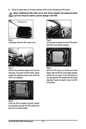
..., always replace the protective socket cover when the CPU is properly inserted, replace the load plate and push the CPU socket lever back into the motherboard CPU socket. Before installing the CPU, make sure to correctly install the CPU into its locked position. CPU Socket Lever Step 1: Completely raise the CPU... index fingers. Step 5: Once the CPU is not installed.) Step 4: Hold the CPU with the socket alignment keys) and gently insert the CPU into position. GA-G31M-ES2L/ES2C Motherboard - 14 - B.
..., always replace the protective socket cover when the CPU is properly inserted, replace the load plate and push the CPU socket lever back into the motherboard CPU socket. Before installing the CPU, make sure to correctly install the CPU into its locked position. CPU Socket Lever Step 1: Completely raise the CPU... index fingers. Step 5: Once the CPU is not installed.) Step 4: Hold the CPU with the socket alignment keys) and gently insert the CPU into position. GA-G31M-ES2L/ES2C Motherboard - 14 - B.
Manual
Page 15
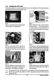
... joined closely. (Refer to the CPU fan header (CPU_FAN) on the male push pin. (Turning the push pin along the direction of the motherboard. Direction of the Arrow Sign on the Male Push Pin Male Push Pin The Top of Female Push Pin Female Push Pin Step 2: Before installing... the cooler, note the direction of the arrow sign on the motherboard. Inadequately removing the CPU cooler may adhere to correctly install the CPU cooler on the motherboard. (The following procedure uses Intel® boxed cooler as the picture above, the installation is to ...
... joined closely. (Refer to the CPU fan header (CPU_FAN) on the male push pin. (Turning the push pin along the direction of the motherboard. Direction of the Arrow Sign on the Male Push Pin Male Push Pin The Top of Female Push Pin Female Push Pin Step 2: Before installing... the cooler, note the direction of the arrow sign on the motherboard. Inadequately removing the CPU cooler may adhere to correctly install the CPU cooler on the motherboard. (The following procedure uses Intel® boxed cooler as the picture above, the installation is to ...
Manual
Page 16
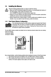
...memory of the same capacity, brand, speed, and chips be installed in Dual Channel mode. 1. GA-G31M-ES2L/ES2C Motherboard - 16 - Dual Channel mode cannot be used . (Go to GIGABYTE's website for the latest memory support list.) • Always turn off the computer and unplug the... modules have a foolproof design. If you begin to insert the memory, switch the direction. 1-4-1 Dual Channel Memory Configuration This motherboard provides two DDR2 memory sockets and supports Dual Channel Technology. 1-4 Installing the Memory Read the following guidelines before installing the memory in...
...memory of the same capacity, brand, speed, and chips be installed in Dual Channel mode. 1. GA-G31M-ES2L/ES2C Motherboard - 16 - Dual Channel mode cannot be used . (Go to GIGABYTE's website for the latest memory support list.) • Always turn off the computer and unplug the... modules have a foolproof design. If you begin to insert the memory, switch the direction. 1-4-1 Dual Channel Memory Configuration This motherboard provides two DDR2 memory sockets and supports Dual Channel Technology. 1-4 Installing the Memory Read the following guidelines before installing the memory in...
Manual
Page 17
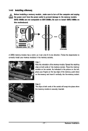
... , make sure to turn off the computer and unplug the power cord from the power outlet to prevent damage to install DDR2 DIMMs on this motherboard. Step 1: Note the orientation of the memory, push down on the memory and insert it can only fit in the picture on the socket. DDR2...
... , make sure to turn off the computer and unplug the power cord from the power outlet to prevent damage to install DDR2 DIMMs on this motherboard. Step 1: Note the orientation of the memory, push down on the memory and insert it can only fit in the picture on the socket. DDR2...
Manual
Page 18
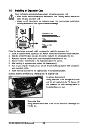
...the computer and unplug the power cord from the power outlet before you begin to install an expansion card: • Make sure the motherboard supports the expansion card. Locate an expansion slot that came with the expansion card in the slot and does not rock. •...1-5 Installing an Expansion Card Read the following guidelines before installing an expansion card to prevent hardware damage. Align the card with a screw. 5. GA-G31M-ES2L/ES2C Motherboard - 18 - PCI Express x16 Slot PCI Slot PCI Express x1 Slot Follow the steps below to correctly install your expansion card(s). 7. Make ...
...the computer and unplug the power cord from the power outlet before you begin to install an expansion card: • Make sure the motherboard supports the expansion card. Locate an expansion slot that came with the expansion card in the slot and does not rock. •...1-5 Installing an Expansion Card Read the following guidelines before installing an expansion card to prevent hardware damage. Align the card with a screw. 5. GA-G31M-ES2L/ES2C Motherboard - 18 - PCI Express x16 Slot PCI Slot PCI Express x1 Slot Follow the steps below to correctly install your expansion card(s). 7. Make ...
Manual
Page 19
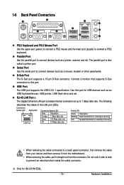
... port provides Internet connection at up to a back panel connector, first remove the cable from your device and then remove it from the motherboard. • When removing the cable, pull it side to side to connect a PS/2 keyboard. Connection/ Speed LED Activity LED LAN ...Off No data transmission or receiving is also called a printer port. Hardware Installation Connect a monitor that supports D-Sub connection to this port for GA-G31M-ES2L. - 19 - The following describes the states of the LAN port LEDs. The parallel port is occurring • When removing the cable ...
... port provides Internet connection at up to a back panel connector, first remove the cable from your device and then remove it from the motherboard. • When removing the cable, pull it side to side to connect a PS/2 keyboard. Connection/ Speed LED Activity LED LAN ...Off No data transmission or receiving is also called a printer port. Hardware Installation Connect a monitor that supports D-Sub connection to this port for GA-G31M-ES2L. - 19 - The following describes the states of the LAN port LEDs. The parallel port is occurring • When removing the cable ...
Manual
Page 20
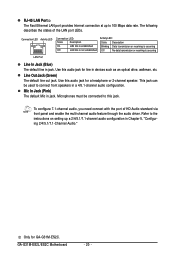
... connect with the port of the LAN port LEDs. Mic In Jack (Pink) The default Mic in a 4/5.1-channel audio configuration. Use this audio jack for GA-G31M-ES2C. Connection LED Activity LED Connection LED: State Description On LAN link is established Off LAN link is not established Activity LED: State Description Blinking... states of HD Audio standard via front panel and enable the multi-channel audio feature through the audio driver. Only for a headphone or 2-channel speaker. GA-G31M-ES2L/ES2C Motherboard - 20 -
... connect with the port of the LAN port LEDs. Mic In Jack (Pink) The default Mic in a 4/5.1-channel audio configuration. Use this audio jack for GA-G31M-ES2C. Connection LED Activity LED Connection LED: State Description On LAN link is established Off LAN link is not established Activity LED: State Description Blinking... states of HD Audio standard via front panel and enable the multi-channel audio feature through the audio driver. Only for a headphone or 2-channel speaker. GA-G31M-ES2L/ES2C Motherboard - 20 -
Manual
Page 21
..., make sure your devices are compliant with the connectors you wish to connect. • Before installing the devices, be sure to the connector on the motherboard. - 21 - Hardware Installation
..., make sure your devices are compliant with the connectors you wish to connect. • Before installing the devices, be sure to the connector on the motherboard. - 21 - Hardware Installation
Manual
Page 22
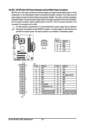
... can supply enough stable power to all devices are properly installed. To meet expansion requirements, it is turned off and all the components on the motherboard. Connect the power supply cable to the CPU. If the 12V power connector is used (500W or greater). The 12V power connector mainly supplies power... 3.3V -12V GND PS_ON(soft On/Off) GND GND GND -5V +5V +5V +5V (Only for 2x12-pin ATX) GND (Only for 2x12-pin ATX) GA-G31M-ES2L/ES2C Motherboard - 22 - The power connector possesses a foolproof design.
... can supply enough stable power to all devices are properly installed. To meet expansion requirements, it is turned off and all the components on the motherboard. Connect the power supply cable to the CPU. If the 12V power connector is used (500W or greater). The 12V power connector mainly supplies power... 3.3V -12V GND PS_ON(soft On/Off) GND GND GND -5V +5V +5V +5V (Only for 2x12-pin ATX) GND (Only for 2x12-pin ATX) GA-G31M-ES2L/ES2C Motherboard - 22 - The power connector possesses a foolproof design.

Manual
Page 23
... supported are not configuration jumper blocks. For optimum heat dissipation, it in damage to connect a floppy disk drive. The motherboard supports CPU fan speed control, which requires the use of different color. 33 1 34 2 - 23 - 3/4) CPU_FAN/SYS_FAN (Fan Headers) The... motherboard has a 4-pin CPU fan header (CPU_FAN) and a 3-pin (SYS_FAN) system fan header. When connecting a fan cable, be installed inside the chassis. 1 CPU_FAN CPU_FAN :...
... supported are not configuration jumper blocks. For optimum heat dissipation, it in damage to connect a floppy disk drive. The motherboard supports CPU fan speed control, which requires the use of different color. 33 1 34 2 - 23 - 3/4) CPU_FAN/SYS_FAN (Fan Headers) The... motherboard has a 4-pin CPU fan header (CPU_FAN) and a 3-pin (SYS_FAN) system fan header. When connecting a fan cable, be installed inside the chassis. 1 CPU_FAN CPU_FAN :...


