
Manual
Page 1
GA-G31M-ES2L/ GA-G31M-ES2C LGA775 socket motherboard for Intel® CoreTM processor family/ Intel® Pentium® processor family/Intel® Celeron® processor family User's Manual Rev. 2301 12ME-G31MES2L-2301R
GA-G31M-ES2L/ GA-G31M-ES2C LGA775 socket motherboard for Intel® CoreTM processor family/ Intel® Pentium® processor family/Intel® Celeron® processor family User's Manual Rev. 2301 12ME-G31MES2L-2301R
Manual
Page 2
Motherboard GA-G31M-ES2L/GA-G31M-ES2C May 20, 2010 Motherboard GA-G31M-ES2L/ GA-G31M-ES2C May 20, 2010
Motherboard GA-G31M-ES2L/GA-G31M-ES2C May 20, 2010 Motherboard GA-G31M-ES2L/ GA-G31M-ES2C May 20, 2010

Manual
Page 3
... mentioned in any means without prior notice. Disclaimer Information in this : "REV: X.X." For product-related information, check on our website at: http://www.gigabyte.com.tw Identifying Your Motherboard Revision The revision number on how to their respective owners. Copyright © 2010 GIGA-BYTE TECHNOLOGY CO., LTD. All rights reserved. For example...
... mentioned in any means without prior notice. Disclaimer Information in this : "REV: X.X." For product-related information, check on our website at: http://www.gigabyte.com.tw Identifying Your Motherboard Revision The revision number on how to their respective owners. Copyright © 2010 GIGA-BYTE TECHNOLOGY CO., LTD. All rights reserved. For example...
Manual
Page 4
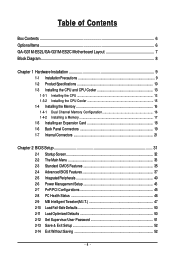
Table of Contents Box Contents ...6 OptionalItems...6 GA-G31M-ES2L/GA-G31M-ES2C Motherboard Layout 7 Block Diagram...8 Chapter 1 Hardware Installation 9 1-1 Installation Precautions 9 1-2 Product Specifications 10 1-3 Installing the CPU and CPU Cooler 13 1-3-1 Installing the CPU 13 1-3-2 Installing the CPU ...
Table of Contents Box Contents ...6 OptionalItems...6 GA-G31M-ES2L/GA-G31M-ES2C Motherboard Layout 7 Block Diagram...8 Chapter 1 Hardware Installation 9 1-1 Installation Precautions 9 1-2 Product Specifications 10 1-3 Installing the CPU and CPU Cooler 13 1-3-1 Installing the CPU 13 1-3-2 Installing the CPU ...
Manual
Page 6
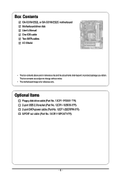
The box contents are for reference only. Box Contents GA-G31M-ES2L or GA-G31M-ES2C motherboard Motherboard driver disk User's Manual One IDE cable Two SATA cables I/O Shield • The box contents above are subject to change without notice. • The motherboard image is for reference only and the actual items shall depend on product package you obtain. Optional Items Floppy disk drive cable (Part No. 12CF1-1FD001-7*R) 2-port USB 2.0 bracket (Part No. 12CR1-1UB030-5*R) 2-port SATA power cable (Part No. 12CF1-2SERPW-0*R) S/PDIF out cable (Part No. 12CR1-1SPOUT-0*R) - 6 -
The box contents are for reference only. Box Contents GA-G31M-ES2L or GA-G31M-ES2C motherboard Motherboard driver disk User's Manual One IDE cable Two SATA cables I/O Shield • The box contents above are subject to change without notice. • The motherboard image is for reference only and the actual items shall depend on product package you obtain. Optional Items Floppy disk drive cable (Part No. 12CF1-1FD001-7*R) 2-port USB 2.0 bracket (Part No. 12CR1-1UB030-5*R) 2-port SATA power cable (Part No. 12CF1-2SERPW-0*R) S/PDIF out cable (Part No. 12CR1-1SPOUT-0*R) - 6 -
Manual
Page 7
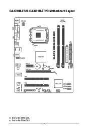
Only for GA-G31M-ES2L. GA-G31M-ES2L/GA-G31M-ES2C Motherboard Layout KB_MS ATX_12V LGA775 CPU_FAN COMA GA-G31M-ES2L/GA-G31M-ES2C DDRII1 DDRII2 PWR_LED F_PANEL LPT LAN VGA R_USB ATX IDE USB AUDIO F_AUDIO AR8131 AR8132 PCIE_1 PCIE_16 IT8718 PCI1 CODEC PCI2 CD_IN SPDIF_O FDD Intel® G31 BAT B_BIOS M_BIOS CLR_CMOS CI SYS_FAN F_USB1F_USB2 Intel® ICH7 SATAII3 SATAII2 SATAII1 SATAII0 Only for GA-G31M-ES2C. - 7 -
Only for GA-G31M-ES2L. GA-G31M-ES2L/GA-G31M-ES2C Motherboard Layout KB_MS ATX_12V LGA775 CPU_FAN COMA GA-G31M-ES2L/GA-G31M-ES2C DDRII1 DDRII2 PWR_LED F_PANEL LPT LAN VGA R_USB ATX IDE USB AUDIO F_AUDIO AR8131 AR8132 PCIE_1 PCIE_16 IT8718 PCI1 CODEC PCI2 CD_IN SPDIF_O FDD Intel® G31 BAT B_BIOS M_BIOS CLR_CMOS CI SYS_FAN F_USB1F_USB2 Intel® ICH7 SATAII3 SATAII2 SATAII1 SATAII0 Only for GA-G31M-ES2C. - 7 -
Manual
Page 9
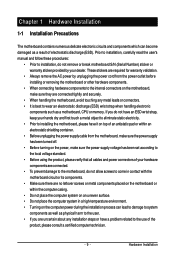
... validation. • Always remove the AC power by your dealer. If you are connected tightly and securely. • When handling the motherboard, avoid touching any installation steps or have it on top of an antistatic pad or within an electrostatic shielding container. • Before unplugging...the computer system on an uneven surface. • Do not place the computer system in a high-temperature environment. • Turning on the motherboard, make sure they are uncertain about any metal leads or connectors. • It is best to wear an electrostatic discharge (ESD) wrist strap...
... validation. • Always remove the AC power by your dealer. If you are connected tightly and securely. • When handling the motherboard, avoid touching any installation steps or have it on top of an antistatic pad or within an electrostatic shielding container. • Before unplugging...the computer system on an uneven surface. • Do not place the computer system in a high-temperature environment. • Turning on the motherboard, make sure they are uncertain about any metal leads or connectors. • It is best to wear an electrostatic discharge (ESD) wrist strap...
Manual
Page 10
... processor/ Intel® Pentium® processor/Intel® Celeron® processor in the LGA 775 package (Go to GIGABYTE's website for the latest CPU support list.) L2 cache varies with CPU 1333/1066/800 MHz ... (Note 1) Dual channel memory architecture Support for DDR2 800/667 MHz memory modules (Go to GIGABYTE's website for the latest memory support list.) Integrated in the North Bridge Realtek ALC883/888B codec ...4 via the USB brackets connected to the internal USB headers) Only for GA-G31M-ES2C. GA-G31M-ES2L/ES2C Motherboard - 10 -
... processor/ Intel® Pentium® processor/Intel® Celeron® processor in the LGA 775 package (Go to GIGABYTE's website for the latest CPU support list.) L2 cache varies with CPU 1333/1066/800 MHz ... (Note 1) Dual channel memory architecture Support for DDR2 800/667 MHz memory modules (Go to GIGABYTE's website for the latest memory support list.) Integrated in the North Bridge Realtek ALC883/888B codec ...4 via the USB brackets connected to the internal USB headers) Only for GA-G31M-ES2C. GA-G31M-ES2L/ES2C Motherboard - 10 -
Manual
Page 12
.../ Celeron Dual-Core/ Celeron 400 Series CPU to enable support for system usage and therefore the actual memory size is reserved for Easy Energy Saver. GA-G31M-ES2L/ES2C Motherboard - 12 - Unique Features Bundled Software Operating System Form Factor Support for @BIOS Support for Q-Flash Support for Xpress BIOS Rescue ...
.../ Celeron Dual-Core/ Celeron 400 Series CPU to enable support for system usage and therefore the actual memory size is reserved for Easy Energy Saver. GA-G31M-ES2L/ES2C Motherboard - 12 - Unique Features Bundled Software Operating System Form Factor Support for @BIOS Support for Q-Flash Support for Xpress BIOS Rescue ...
Manual
Page 13
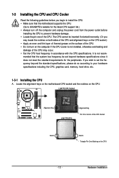
Locate the alignment keys on the motherboard CPU socket and the notches on the computer if the CPU cooler is not recom- Hardware Installation LGA775 CPU Socket Alignment Key LGA 775 CPU ... installing the CPU to your hardware specifications including the CPU, graphics card, memory, hard drive, etc. 1-3-1 Installing the CPU A. mended that the motherboard supports the CPU. (Go to GIGABYTE's website for the peripherals. 1-3 Installing the CPU and CPU Cooler Read the following guidelines before you begin to install the CPU: • Make...
Locate the alignment keys on the motherboard CPU socket and the notches on the computer if the CPU cooler is not recom- Hardware Installation LGA775 CPU Socket Alignment Key LGA 775 CPU ... installing the CPU to your hardware specifications including the CPU, graphics card, memory, hard drive, etc. 1-3-1 Installing the CPU A. mended that the motherboard supports the CPU. (Go to GIGABYTE's website for the peripherals. 1-3 Installing the CPU and CPU Cooler Read the following guidelines before you begin to install the CPU: • Make...
Manual
Page 14
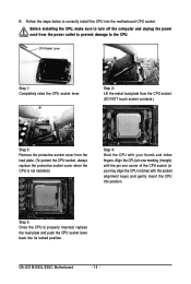
... socket lever. Step 5: Once the CPU is not installed.) Step 4: Hold the CPU with the socket alignment keys) and gently insert the CPU into position. GA-G31M-ES2L/ES2C Motherboard - 14 - Before installing the CPU, make sure to the CPU. Step 2: Lift the metal load plate from the CPU socket. (DO NOT touch socket..., always replace the protective socket cover when the CPU is properly inserted, replace the load plate and push the CPU socket lever back into the motherboard CPU socket. B.
... socket lever. Step 5: Once the CPU is not installed.) Step 4: Hold the CPU with the socket alignment keys) and gently insert the CPU into position. GA-G31M-ES2L/ES2C Motherboard - 14 - Before installing the CPU, make sure to the CPU. Step 2: Lift the metal load plate from the CPU socket. (DO NOT touch socket..., always replace the protective socket cover when the CPU is properly inserted, replace the load plate and push the CPU socket lever back into the motherboard CPU socket. B.
Manual
Page 15
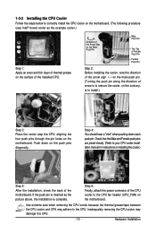
1-3-2 Installing the CPU Cooler Follow the steps below to correctly install the CPU cooler on the motherboard. (The following procedure uses Intel® boxed cooler as the picture above, the installation is to install.) Step 3: Place the cooler atop the CPU, aligning ... the cooler.) Step 5: After the installation, check the back of arrow is to the CPU fan header (CPU_FAN) on the motherboard. Step 4: You should hear a "click" when pushing down on the motherboard. If the push pin is inserted as the example cooler.) Step 1: Apply an even and thin layer of thermal grease...
1-3-2 Installing the CPU Cooler Follow the steps below to correctly install the CPU cooler on the motherboard. (The following procedure uses Intel® boxed cooler as the picture above, the installation is to install.) Step 3: Place the cooler atop the CPU, aligning ... the cooler.) Step 5: After the installation, check the back of arrow is to the CPU fan header (CPU_FAN) on the motherboard. Step 4: You should hear a "click" when pushing down on the motherboard. If the push pin is inserted as the example cooler.) Step 1: Apply an even and thin layer of thermal grease...
Manual
Page 16
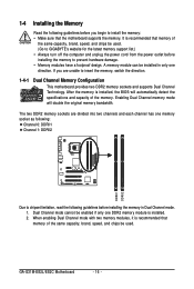
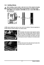
After the memory is recommended that the motherboard supports the memory. GA-G31M-ES2L/ES2C Motherboard - 16 - 1-4 Installing the Memory Read the following guidelines before you are divided into two channels and each channel has one memory socket as following: Channel 0:... sockets are unable to install the memory: • Make sure that memory of the same capacity, brand, speed, and chips be used . (Go to GIGABYTE's website for the latest memory support list.) • Always turn off the computer and unplug the power cord from the power outlet before installing the...
After the memory is recommended that the motherboard supports the memory. GA-G31M-ES2L/ES2C Motherboard - 16 - 1-4 Installing the Memory Read the following guidelines before you are divided into two channels and each channel has one memory socket as following: Channel 0:... sockets are unable to install the memory: • Make sure that memory of the same capacity, brand, speed, and chips be used . (Go to GIGABYTE's website for the latest memory support list.) • Always turn off the computer and unplug the power cord from the power outlet before installing the...
Manual
Page 17
... indicated in the picture on the memory and insert it can only fit in the memory sockets. Hardware Installation Place the memory module on this motherboard. Notch DDR2 DIMM A DDR2 memory module has a notch, so it vertically into place when the memory module is securely inserted. - 17 - Spread the retaining clips...
... indicated in the picture on the memory and insert it can only fit in the memory sockets. Hardware Installation Place the memory module on this motherboard. Notch DDR2 DIMM A DDR2 memory module has a notch, so it vertically into place when the memory module is securely inserted. - 17 - Spread the retaining clips...
Manual
Page 18
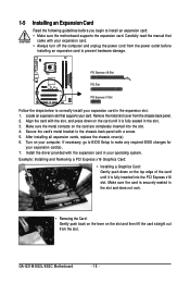
... your operating system. Turn on the card are completely inserted into the PCI Express x16 slot. Make sure the metal contacts on your expansion card(s). 7. GA-G31M-ES2L/ES2C Motherboard - 18 - Make sure the card is fully inserted into the slot. 4. PCI Express x16 Slot PCI Slot PCI Express x1 Slot Follow the steps...
... your operating system. Turn on the card are completely inserted into the PCI Express x16 slot. Make sure the metal contacts on your expansion card(s). 7. GA-G31M-ES2L/ES2C Motherboard - 18 - Make sure the card is fully inserted into the slot. 4. PCI Express x16 Slot PCI Slot PCI Express x1 Slot Follow the steps...
Manual
Page 19
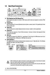
...occurring • When removing the cable connected to a back panel connector, first remove the cable from your device and then remove it from the motherboard. • When removing the cable, pull it side to side to connect devices such as an USB keyboard/mouse, USB printer, USB flash drive... (green) to connect a PS/2 mouse and the lower port (purple) to 1 Gbps data rate. Parallel Port Use the parallel port to this port for GA-G31M-ES2L. - 19 - Connect a monitor that supports D-Sub connection to connect devices such as a printer, scanner and etc. USB Port The USB port supports ...
...occurring • When removing the cable connected to a back panel connector, first remove the cable from your device and then remove it from the motherboard. • When removing the cable, pull it side to side to connect devices such as an USB keyboard/mouse, USB printer, USB flash drive... (green) to connect a PS/2 mouse and the lower port (purple) to 1 Gbps data rate. Parallel Port Use the parallel port to this port for GA-G31M-ES2L. - 19 - Connect a monitor that supports D-Sub connection to connect devices such as a printer, scanner and etc. USB Port The USB port supports ...
Manual
Page 20
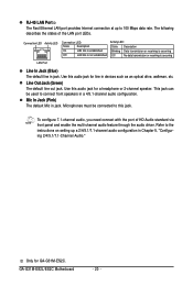
... or receiving is occurring LAN Port Line In Jack (Blue) The default line in jack. GA-G31M-ES2L/ES2C Motherboard - 20 - This jack can be connected to connect front speakers in a 4/5.1-channel audio configuration. Use this audio jack for GA-G31M-ES2C. To configure 7.1-channel audio, you need connect with the port of the LAN port LEDs...
... or receiving is occurring LAN Port Line In Jack (Blue) The default line in jack. GA-G31M-ES2L/ES2C Motherboard - 20 - This jack can be connected to connect front speakers in a 4/5.1-channel audio configuration. Use this audio jack for GA-G31M-ES2C. To configure 7.1-channel audio, you need connect with the port of the LAN port LEDs...
Manual
Page 21
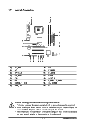
... / 1 / 2 / 3 8) PWR_LED 9) BAT 10) F_PANEL 11) F_AUDIO 12) CD_IN 13) SPDIF_O 14) F_USB1 / F_USB2 15) CLR_CMOS 16) CI Read the following guidelines before turning on the motherboard. - 21 - Unplug the power cord from the power outlet to prevent damage to the devices. • After installing the device and before connecting external devices...
... / 1 / 2 / 3 8) PWR_LED 9) BAT 10) F_PANEL 11) F_AUDIO 12) CD_IN 13) SPDIF_O 14) F_USB1 / F_USB2 15) CLR_CMOS 16) CI Read the following guidelines before turning on the motherboard. - 21 - Unplug the power cord from the power outlet to prevent damage to the devices. • After installing the device and before connecting external devices...
Manual
Page 22
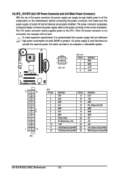
The power connector possesses a foolproof design. To meet expansion requirements, it is turned off and all the components on the motherboard. Before connecting the power connector, first make sure the power supply is recommended that a power supply that does not provide the required power, the...3V -12V GND PS_ON(soft On/Off) GND GND GND -5V +5V +5V +5V (Only for 2x12-pin ATX) GND (Only for 2x12-pin ATX) GA-G31M-ES2L/ES2C Motherboard - 22 - The 12V power connector mainly supplies power to the power connector in the correct orientation. Connect the power supply cable to the CPU.
The power connector possesses a foolproof design. To meet expansion requirements, it is turned off and all the components on the motherboard. Before connecting the power connector, first make sure the power supply is recommended that a power supply that does not provide the required power, the...3V -12V GND PS_ON(soft On/Off) GND GND GND -5V +5V +5V +5V (Only for 2x12-pin ATX) GND (Only for 2x12-pin ATX) GA-G31M-ES2L/ES2C Motherboard - 22 - The 12V power connector mainly supplies power to the power connector in the correct orientation. Connect the power supply cable to the CPU.

Manual
Page 23
... connector and the floppy disk drive cable. Before connecting a floppy disk drive, be sure to connect it is used to connect a floppy disk drive. The motherboard supports CPU fan speed control, which requires the use of different color. 33 1 34 2 - 23 - Hardware Installation Overheating may hang. • These fan ...correct orientation (the black connector wire is typically designated by a stripe of a CPU fan with fan speed control design. 3/4) CPU_FAN/SYS_FAN (Fan Headers) The motherboard has a 4-pin CPU fan header (CPU_FAN) and a 3-pin (SYS_FAN) system fan header.
... connector and the floppy disk drive cable. Before connecting a floppy disk drive, be sure to connect it is used to connect a floppy disk drive. The motherboard supports CPU fan speed control, which requires the use of different color. 33 1 34 2 - 23 - Hardware Installation Overheating may hang. • These fan ...correct orientation (the black connector wire is typically designated by a stripe of a CPU fan with fan speed control design. 3/4) CPU_FAN/SYS_FAN (Fan Headers) The motherboard has a 4-pin CPU fan header (CPU_FAN) and a 3-pin (SYS_FAN) system fan header.


