Manual
Page 11
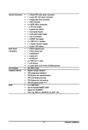
Hardware Installation Internal Connectors 1 x 24-pin ATX main power connector 1 x 4-pin ATX 12V power connector 1 x floppy disk drive connector 1 x IDE connector 4 x SATA 3Gb/s connectors ...front panel audio header 1 x CD In connector 1 x S/PDIF Out header 2 x USB 2.0/1.1 headers 1 x chassis intrusion header 1 x power LED header Back Panel 1 x PS/2 keyboard port Connectors 1 x PS/2 mouse port 1 x parallel port 1 x serial port 1 x D-Sub ...
Hardware Installation Internal Connectors 1 x 24-pin ATX main power connector 1 x 4-pin ATX 12V power connector 1 x floppy disk drive connector 1 x IDE connector 4 x SATA 3Gb/s connectors ...front panel audio header 1 x CD In connector 1 x S/PDIF Out header 2 x USB 2.0/1.1 headers 1 x chassis intrusion header 1 x power LED header Back Panel 1 x PS/2 keyboard port Connectors 1 x PS/2 mouse port 1 x parallel port 1 x serial port 1 x D-Sub ...
Manual
Page 25
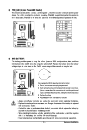
... local dealer if you are not able to replace the battery by removing the battery: 1. The LED keeps blinking when the system is in S3/S4 sleep state or powered off (S5). The LED is off when the system is in S1 sleep state. Gently remove the battery from the battery...the CMOS when the computer is turned off. Plug in the power cord and restart your computer. • Always turn off your computer and unplug the power cord. 2. Hardware Installation 8) PWR_LED (System Power LED Header) This header can be used to connect a system power LED on when the system is operating. Pin No. Replace the...
... local dealer if you are not able to replace the battery by removing the battery: 1. The LED keeps blinking when the system is in S3/S4 sleep state or powered off (S5). The LED is off when the system is in S1 sleep state. Gently remove the battery from the battery...the CMOS when the computer is turned off. Plug in the power cord and restart your computer. • Always turn off your computer and unplug the power cord. 2. Hardware Installation 8) PWR_LED (System Power LED Header) This header can be used to connect a system power LED on when the system is operating. Pin No. Replace the...
Manual
Page 26
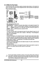
... LED): System Status LED Connects to the power status indicator on the chassis front panel to the pin assignments below. You may configure the way to turn off your chassis front panel module to this header according to this header, make sure the wire assignments and the pin assignments are matched correctly. GA-G31M-ES2L/ES2C...
... LED): System Status LED Connects to the power status indicator on the chassis front panel to the pin assignments below. You may configure the way to turn off your chassis front panel module to this header according to this header, make sure the wire assignments and the pin assignments are matched correctly. GA-G31M-ES2L/ES2C...


