Manual
Page 4
...OptionalItems...6 GA-G31-S3L Motherboard Layout 7 Block Diagram...8 Chapter 1 Hardware Installation 9 1-1 Installation Precautions 9 1-2 Product Specifications 10 1-3 Installing the CPU and CPU Cooler 13 1-3-1 Installing the CPU 13 1-3-2 Installing the CPU Cooler 15 1-4 Installing the Memory 16 1-4-1 Dual Channel Memory Configuration 16 1-4-2 Installing a Memory 17 1-5 Installing an Expansion Card 18 1-6 Back Panel Connectors 19 1-7 Internal Connectors 21 Chapter 2 BIOS Setup 31 2-1 Startup Screen 32 2-2 The Main Menu 33 2-3 Standard CMOS Features 35 2-4 Advanced BIOS Features...
...OptionalItems...6 GA-G31-S3L Motherboard Layout 7 Block Diagram...8 Chapter 1 Hardware Installation 9 1-1 Installation Precautions 9 1-2 Product Specifications 10 1-3 Installing the CPU and CPU Cooler 13 1-3-1 Installing the CPU 13 1-3-2 Installing the CPU Cooler 15 1-4 Installing the Memory 16 1-4-1 Dual Channel Memory Configuration 16 1-4-2 Installing a Memory 17 1-5 Installing an Expansion Card 18 1-6 Back Panel Connectors 19 1-7 Internal Connectors 21 Chapter 2 BIOS Setup 31 2-1 Startup Screen 32 2-2 The Main Menu 33 2-3 Standard CMOS Features 35 2-4 Advanced BIOS Features...
Manual
Page 10
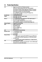
... In Š RTL 8111B chip (10/100/1000 Mbit) Š 1 x PCI Express x16 slot Š 3 x PCI Express x1 slots Š 3 x PCI slots Š South Bridge: - 1 x IDE connector supporting ATA-100/66/33 and up to 2 IDE devices - 4 x SATA 3Gb/s connectors supporting up to 4 SATA 3Gb/s devices Š iTE IT8718 chip: - 1 x floppy disk drive connector supporting up to 1 floppy disk drive Š Integrated in the South Bridge Š Up to 8 USB 2.0/1.1 ports (4 on the back panel, 4 via the USB brackets connected to the internal USB headers) GA-G31-S3L Motherboard - 10 -
... In Š RTL 8111B chip (10/100/1000 Mbit) Š 1 x PCI Express x16 slot Š 3 x PCI Express x1 slots Š 3 x PCI slots Š South Bridge: - 1 x IDE connector supporting ATA-100/66/33 and up to 2 IDE devices - 4 x SATA 3Gb/s connectors supporting up to 4 SATA 3Gb/s devices Š iTE IT8718 chip: - 1 x floppy disk drive connector supporting up to 1 floppy disk drive Š Integrated in the South Bridge Š Up to 8 USB 2.0/1.1 ports (4 on the back panel, 4 via the USB brackets connected to the internal USB headers) GA-G31-S3L Motherboard - 10 -
Manual
Page 16
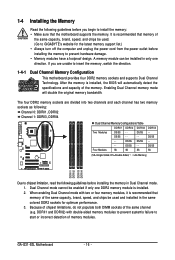
... the memory to insert the memory, switch the direction. 1-4-1 Dual Channel Memory Configuration This motherboard provides four DDR2 memory sockets and supports Dual Channel Technology. A memory module can be enabled if only one direction. If you begin to GIGABYTE's website for optimum performance. 3. Enabling Dual Channel memory mode will automatically detect the specifications and capacity of memory modules. Dual Channel mode cannot be installed in only one DDR2 memory module is installed, the BIOS will double the original memory bandwidth. GA-G31-S3L Motherboard - 16...
... the memory to insert the memory, switch the direction. 1-4-1 Dual Channel Memory Configuration This motherboard provides four DDR2 memory sockets and supports Dual Channel Technology. A memory module can be enabled if only one direction. If you begin to GIGABYTE's website for optimum performance. 3. Enabling Dual Channel memory mode will automatically detect the specifications and capacity of memory modules. Dual Channel mode cannot be installed in only one DDR2 memory module is installed, the BIOS will double the original memory bandwidth. GA-G31-S3L Motherboard - 16...
Manual
Page 18
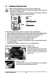
... end of the PCI Express x16 slot. • Removing the Card: Press the white latch at the end of the PCI Express x16 slot to release the card and then pull the card straight up from the slot. GA-G31-S3L Motherboard - 18 - Carefully read the manual that supports your expansion card. • Always turn off the computer and unplug the power cord from the chassis back panel. 2. PCI Express x1 Slot PCI Express x16 Slot PCI Slot Follow the...
... end of the PCI Express x16 slot. • Removing the Card: Press the white latch at the end of the PCI Express x16 slot to release the card and then pull the card straight up from the slot. GA-G31-S3L Motherboard - 18 - Carefully read the manual that supports your expansion card. • Always turn off the computer and unplug the power cord from the chassis back panel. 2. PCI Express x1 Slot PCI Express x16 Slot PCI Slot Follow the...
Manual
Page 23
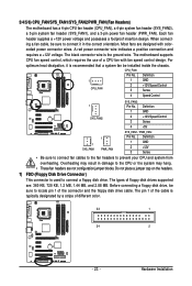
... connect a floppy disk drive. Each fan header supplies a +12V power voltage and possesses a foolproof insertion design. CPU_FAN: Pin No. 3/4/5/6) CPU_FAN/SYS_FAN1/SYS_FAN2/PWR_FAN (Fan Headers) The motherboard has a 4-pin CPU fan header (CPU_FAN), a 4-pin system fan header (SYS_FAN2), a 3-pin system fan header (SYS_FAN1), and a 3-pin power fan header (PWR_FAN). Most fans are designed with fan speed control design. The black connector wire is recommended that a system fan be installed inside the chassis. Definition 1 CPU_FAN 1 GND 2 +12V/Speed Control 3 Sense 4 Speed Control...
... connect a floppy disk drive. Each fan header supplies a +12V power voltage and possesses a foolproof insertion design. CPU_FAN: Pin No. 3/4/5/6) CPU_FAN/SYS_FAN1/SYS_FAN2/PWR_FAN (Fan Headers) The motherboard has a 4-pin CPU fan header (CPU_FAN), a 4-pin system fan header (SYS_FAN2), a 3-pin system fan header (SYS_FAN1), and a 3-pin power fan header (PWR_FAN). Most fans are designed with fan speed control design. The black connector wire is recommended that a system fan be installed inside the chassis. Definition 1 CPU_FAN 1 GND 2 +12V/Speed Control 3 Sense 4 Speed Control...
Manual
Page 25
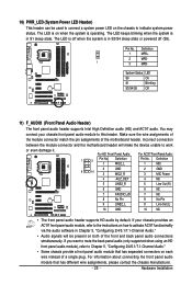
...) F_AUDIO (Front Panel Audio Header) The front panel audio header supports Intel High Definition audio (HD) and AC'97 audio. Incorrect connection between the module connector and the motherboard header will make the device unable to activate AC'97 functioninality via the audio software in Chapter 5, "Configuring 2/4/5.1/7.1-Channel Audio." • Audio signals will be used to connect a system power LED on the chassis to this header. If your chassis front panel audio module to indicate system power status. The LED is off...
...) F_AUDIO (Front Panel Audio Header) The front panel audio header supports Intel High Definition audio (HD) and AC'97 audio. Incorrect connection between the module connector and the motherboard header will make the device unable to activate AC'97 functioninality via the audio software in Chapter 5, "Configuring 2/4/5.1/7.1-Channel Audio." • Audio signals will be used to connect a system power LED on the chassis to this header. If your chassis front panel audio module to indicate system power status. The LED is off...
Manual
Page 26
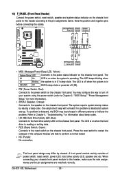
... panel. RESRES+ NC IDE Hard Disk Reset Active LED Switch • MSG (Message/Power/Sleep LED, Yellow): System Status LED Connects to the power status indicator on the chassis front panel to this header, make sure the wire assignments and the pin assignments are matched correctly. You may configure the way to turn off (S5). • PW (Power Switch, Red): Connects to the speaker on the chassis front panel. One single short beep will be heard if no problem...
... panel. RESRES+ NC IDE Hard Disk Reset Active LED Switch • MSG (Message/Power/Sleep LED, Yellow): System Status LED Connects to the power status indicator on the chassis front panel to this header, make sure the wire assignments and the pin assignments are matched correctly. You may configure the way to turn off (S5). • PW (Power Switch, Red): Connects to the speaker on the chassis front panel. One single short beep will be heard if no problem...
Manual
Page 29
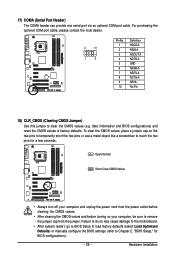
... ANo Pin 18) CLR_CMOS (Clearing CMOS Jumper) Use this jumper to factory defaults. Failure to do so may cause damage to the motherboard. • After system restart, go to BIOS Setup to load factory defaults (select Load Optimized Defaults) or manually configure the BIOS settings (refer to Chapter 2, "BIOS Setup," for a few seconds. Hardware Installation Open: Normal Short: Clear CMOS Values • Always turn off your computer and unplug the power cord from the power outlet before clearing the CMOS...
... ANo Pin 18) CLR_CMOS (Clearing CMOS Jumper) Use this jumper to factory defaults. Failure to do so may cause damage to the motherboard. • After system restart, go to BIOS Setup to load factory defaults (select Load Optimized Defaults) or manually configure the BIOS settings (refer to Chapter 2, "BIOS Setup," for a few seconds. Hardware Installation Open: Normal Short: Clear CMOS Values • Always turn off your computer and unplug the power cord from the power outlet before clearing the CMOS...
Manual
Page 32
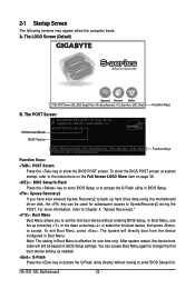
... used for G31-S3L F2c . . . . : BIOS Setup/Q-Flash : XpressRecovery2 : Boot Menu : Qflash 11/14/2007-G31-ICH7-6A89OG0HC-00 Function Keys Function Keys: : POST Screen Press the key to access the Q-Flash utility in Boot Menu is effective for one time only. You can be based on page 38. : BIOS Setup/Q-Flash Press the key to enter BIOS Setup or to show the BIOS POST screen. To exit Boot Menu, press . Motherboard Model BIOS Version Intel G31 BIOS for subsequent access to enter BIOS Setup first. In Boot Menu, use the up hard drive data using the motherboard driver disk...
... used for G31-S3L F2c . . . . : BIOS Setup/Q-Flash : XpressRecovery2 : Boot Menu : Qflash 11/14/2007-G31-ICH7-6A89OG0HC-00 Function Keys Function Keys: : POST Screen Press the key to access the Q-Flash utility in Boot Menu is effective for one time only. You can be based on page 38. : BIOS Setup/Q-Flash Press the key to enter BIOS Setup or to show the BIOS POST screen. To exit Boot Menu, press . Motherboard Model BIOS Version Intel G31 BIOS for subsequent access to enter BIOS Setup first. In Boot Menu, use the up hard drive data using the motherboard driver disk...
Manual
Page 34
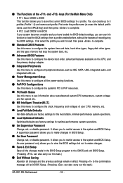
..., hard drive types, floppy disk drive types, and the type of errors that stop the system boot, etc. „ Advanced BIOS Features Use this menu to configure the device boot order, advanced features available on the CPU, and the primary display adapter. „ Integrated Peripherals Use this menu to configure all peripheral devices, such as IDE, SATA, USB, integrated audio, and integrated LAN, etc. „ Power Management Setup Use this menu to configure all the power-saving functions. „ PnP/PCI Configurations Use this menu to configure the...
..., hard drive types, floppy disk drive types, and the type of errors that stop the system boot, etc. „ Advanced BIOS Features Use this menu to configure the device boot order, advanced features available on the CPU, and the primary display adapter. „ Integrated Peripherals Use this menu to configure all peripheral devices, such as IDE, SATA, USB, integrated audio, and integrated LAN, etc. „ Power Management Setup Use this menu to configure all the power-saving functions. „ PnP/PCI Configurations Use this menu to configure the...
Manual
Page 37
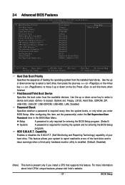
... Limit CPUID Max. Use the up or down arrow key to select a device and press to accept. Options are: Floppy, LS120, Hard Disk, CDROM, ZIP, USB-FDD, USB-ZIP, USB-CDROM, USB-HDD, LAN, Disabled. Password Check Specifies whether a password is required for booting the system and for entering the BIOS Setup program. BIOS Setup 2-4 Advanced BIOS Features CMOS Setup Utility-Copyright (C) 1984-2007 Award Software Advanced BIOS Features ` Hard Disk Boot Priority First Boot Device [Press Enter] [Floppy] Item Help Menu Level` Second Boot Device Third Boot Device Password Check [Hard Disk...
... Limit CPUID Max. Use the up or down arrow key to select a device and press to accept. Options are: Floppy, LS120, Hard Disk, CDROM, ZIP, USB-FDD, USB-ZIP, USB-CDROM, USB-HDD, LAN, Disabled. Password Check Specifies whether a password is required for booting the system and for entering the BIOS Setup program. BIOS Setup 2-4 Advanced BIOS Features CMOS Setup Utility-Copyright (C) 1984-2007 Award Software Advanced BIOS Features ` Hard Disk Boot Priority First Boot Device [Press Enter] [Floppy] Item Help Menu Level` Second Boot Device Third Boot Device Password Check [Hard Disk...
Manual
Page 38
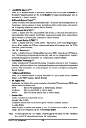
... systems and applications in system halt state. When enabled, the CPU core frequency and voltage will allow a platform to display the GIGABYTE Logo at system startup. Disabled displays normal POST message. (Default: Enabled) Init Display First Specifies the first initiation of the monitor display from the installed PCI graphics card, PCI Express graphics card or the onboard VGA. PCI Sets the PCI graphics card as the first display. (Default) Onboard Sets the onboard VGA as multiple virtual systems. (Default: Enabled) Full Screen LOGO Show Allows you to determine whether to...
... systems and applications in system halt state. When enabled, the CPU core frequency and voltage will allow a platform to display the GIGABYTE Logo at system startup. Disabled displays normal POST message. (Default: Enabled) Init Display First Specifies the first initiation of the monitor display from the installed PCI graphics card, PCI Express graphics card or the onboard VGA. PCI Sets the PCI graphics card as the first display. (Default) Onboard Sets the onboard VGA as multiple virtual systems. (Default: Enabled) Full Screen LOGO Show Allows you to determine whether to...
Manual
Page 40
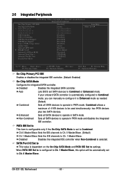
...CMOS Setup Utility-Copyright (C) 1984-2007 Award Software Integrated Peripherals On-Chip Primary PCI IDE On-Chip SATA Mode x PATA IDE Set to SATA Port0/2 Set to SATA Port1/3 Set to be automatically set to Combined or Enhanced mode. Combined allows a maximum of 4 ATA devices to USB Controller USB 2.0 Controller USB Keyboard Support USB Mouse Support Legacy USB storage detect Azalia Codec Onboard H/W LAN ` SMART LAN Onboard LAN Boot ROM Onboard Serial Port 1 Onboard Parallel Port Parallel Port Mode [Enabled] [Auto] Ch.0 Master/Slave Ch.2 Master/Slave Ch.3 Master/Slave [Enabled] [Enabled...
...CMOS Setup Utility-Copyright (C) 1984-2007 Award Software Integrated Peripherals On-Chip Primary PCI IDE On-Chip SATA Mode x PATA IDE Set to SATA Port0/2 Set to SATA Port1/3 Set to be automatically set to Combined or Enhanced mode. Combined allows a maximum of 4 ATA devices to USB Controller USB 2.0 Controller USB Keyboard Support USB Mouse Support Legacy USB storage detect Azalia Codec Onboard H/W LAN ` SMART LAN Onboard LAN Boot ROM Onboard Serial Port 1 Onboard Parallel Port Parallel Port Mode [Enabled] [Auto] Ch.0 Master/Slave Ch.2 Master/Slave Ch.3 Master/Slave [Enabled] [Enabled...
Manual
Page 41
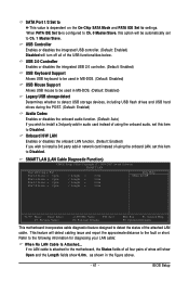
... install a 3rd party add-in audio card instead of using the onboard audio, set this item to Disabled. If no LAN cable is attached to the motherboard, the Status fields of all of the USB functionalities below. SMART LAN (LAN Cable Diagnostic Function) CMOS Setup Utility-Copyright (C) 1984-2007 Award Software SMART LAN Start detecting at Port..... Refer to detect the status of the attached LAN cable. SATA Port 1/3 Set to This value is configured to Ch. 0 Master/Slave, this option will turn...
... install a 3rd party add-in audio card instead of using the onboard audio, set this item to Disabled. If no LAN cable is attached to the motherboard, the Status fields of all of the USB functionalities below. SMART LAN (LAN Cable Diagnostic Function) CMOS Setup Utility-Copyright (C) 1984-2007 Award Software SMART LAN Start detecting at Port..... Refer to detect the status of the attached LAN cable. SATA Port 1/3 Set to This value is configured to Ch. 0 Master/Slave, this option will turn...
Manual
Page 42
.../1000 Mbps in Windows mode or when the LAN Boot ROM is the approximate length of wires, the Status field will show Open, and the length shown is activated. Onboard Parallel Port Enables or disables the onboard parallel port (LPT) and specifies its base I /O address and corresponding interrupt. GA-G31-S3L Motherboard - 42 - Parallel Port Mode Selects an operating mode for the onboard parallel (LPT) port. Options are : Auto, 3F8/IRQ4 (default), 2F8/IRQ3...
.../1000 Mbps in Windows mode or when the LAN Boot ROM is the approximate length of wires, the Status field will show Open, and the length shown is activated. Onboard Parallel Port Enables or disables the onboard parallel port (LPT) and specifies its base I /O address and corresponding interrupt. GA-G31-S3L Motherboard - 42 - Parallel Port Mode Selects an operating mode for the onboard parallel (LPT) port. Options are : Auto, 3F8/IRQ4 (default), 2F8/IRQ3...
Manual
Page 46
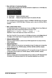
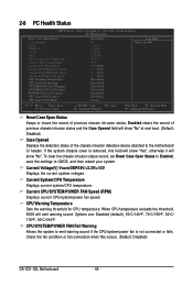
... Enabled, save the settings to emit warning sound if the CPU/system/power fan is removed, this occurs. (Default: Disabled) GA-G31-S3L Motherboard - 46 - Current System/CPU Temperature Displays current system/CPU temperature. When CPU temperature exceeds the threshold, BIOS will show "No". Check the fan condition or fan connection when this field will show "No" at next boot. (Default: Disabled) Case Opened Displays the detection status of previous chassis intrusion status. CPU/SYSTEM/POWER FAN Fail Warning Allows the system to CMOS...
... Enabled, save the settings to emit warning sound if the CPU/system/power fan is removed, this occurs. (Default: Disabled) GA-G31-S3L Motherboard - 46 - Current System/CPU Temperature Displays current system/CPU temperature. When CPU temperature exceeds the threshold, BIOS will show "No". Check the fan condition or fan connection when this field will show "No" at next boot. (Default: Disabled) Case Opened Displays the detection status of previous chassis intrusion status. CPU/SYSTEM/POWER FAN Fail Warning Allows the system to CMOS...
Manual
Page 47
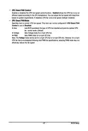
... installed and sets the optimal CPU fan control mode. (Default) Voltage Sets Voltage mode for a 4-pin CPU fan that is set for a 4-pin CPU fan. This item can not be set to Disabled. BIOS Setup If disabled, CPU fan runs at different speed according to control CPU fan speed. CPU Smart FAN Control Enables or disables the CPU fan speed control function. However, for a 3-pin CPU fan. PWM Sets PWM mode for a 3-pin CPU fan or a 4-pin CPU fan. Enabled allows the CPU fan to run at full speed. (Default: Enabled) CPU Smart FAN Mode Specifies how to the CPU temperature...
... installed and sets the optimal CPU fan control mode. (Default) Voltage Sets Voltage mode for a 4-pin CPU fan that is set for a 4-pin CPU fan. This item can not be set to Disabled. BIOS Setup If disabled, CPU fan runs at different speed according to control CPU fan speed. CPU Smart FAN Control Enables or disables the CPU fan speed control function. However, for a 3-pin CPU fan. PWM Sets PWM mode for a 3-pin CPU fan or a 4-pin CPU fan. Enabled allows the CPU fan to run at full speed. (Default: Enabled) CPU Smart FAN Mode Specifies how to the CPU temperature...
Manual
Page 48
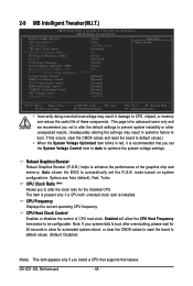
..., clear the CMOS values and reset the board to default values.) • When the System Voltage Optimized item blinks in red, it is installed. CPU Frequency Displays the current operating CPU frequency. Auto allows the BIOS to CPU, chipset, or memory and reduce the useful life of CPU host clock. GA-G31-S3L Motherboard - 48 - 2-9 MB Intelligent Tweaker(M.I.T.) CMOS Setup Utility-Copyright (C) 1984-2007 Award Software MB Intelligent Tweaker(M.I.T.) Robust Graphics Booster CPU Clock Ratio (Note) CPU Frequency CPU Host Clock Control x CPU Host Frequency (Mhz) PCI Express Frequency...
..., clear the CMOS values and reset the board to default values.) • When the System Voltage Optimized item blinks in red, it is installed. CPU Frequency Displays the current operating CPU frequency. Auto allows the BIOS to CPU, chipset, or memory and reduce the useful life of CPU host clock. GA-G31-S3L Motherboard - 48 - 2-9 MB Intelligent Tweaker(M.I.T.) CMOS Setup Utility-Copyright (C) 1984-2007 Award Software MB Intelligent Tweaker(M.I.T.) Robust Graphics Booster CPU Clock Ratio (Note) CPU Frequency CPU Host Clock Control x CPU Host Frequency (Mhz) PCI Express Frequency...
Manual
Page 53
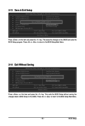
... and press the key. This exits the BIOS Setup without saving the changes made in BIOS Setup to the CMOS and exits the BIOS Setup program. This saves the changes to the CMOS. 2-13 Save & Exit Setup CMOS Setup Utility-Copyright (C) 1984-2007 Award Software ` Standard CMOS Features Load Fail-Safe Defaults ` Advanced BIOS Features Load Optimized Defaults ` Integrated Peripherals Set Supervisor Password ` Power Management Setup Save to CMOS and EXIT (SYe/tNU)?seYr Password ` PnP/PCI Configurations Save & Exit Setup ` PC Health...
... and press the key. This exits the BIOS Setup without saving the changes made in BIOS Setup to the CMOS and exits the BIOS Setup program. This saves the changes to the CMOS. 2-13 Save & Exit Setup CMOS Setup Utility-Copyright (C) 1984-2007 Award Software ` Standard CMOS Features Load Fail-Safe Defaults ` Advanced BIOS Features Load Optimized Defaults ` Integrated Peripherals Set Supervisor Password ` Power Management Setup Save to CMOS and EXIT (SYe/tNU)?seYr Password ` PnP/PCI Configurations Save & Exit Setup ` PC Health...
Manual
Page 78
... battery. 4. Refer to enter BIOS Setup. Select "Load Fail-Safe Defaults" (or "Load Optimized Defaults") to show the advanced options. A: The following Award BIOS beep code descriptions may help you identify possible computer problems. (For reference only.) 1 short: System boots successfully 2 short: CMOS setting error 1 long, 1 short: Memory or motherboard error 1 long, 2 short: Monitor or graphics card error 1 long, 3 short: Keyboard error 1 long, 9 short: BIOS ROM error Continuous long beeps: Graphics card not inserted properly Continuous short beeps: Power error GA-G31-S3L...
... battery. 4. Refer to enter BIOS Setup. Select "Load Fail-Safe Defaults" (or "Load Optimized Defaults") to show the advanced options. A: The following Award BIOS beep code descriptions may help you identify possible computer problems. (For reference only.) 1 short: System boots successfully 2 short: CMOS setting error 1 long, 1 short: Memory or motherboard error 1 long, 2 short: Monitor or graphics card error 1 long, 3 short: Keyboard error 1 long, 9 short: BIOS ROM error Continuous long beeps: Graphics card not inserted properly Continuous short beeps: Power error GA-G31-S3L...


