Manual
Page 1
GA-EX38-DS4 LGA775 socket motherboard for Intel® CoreTM processor family/ Intel® Pentium® processor family/Intel® Celeron® processor family User's Manual Rev. 1101 12ME-EX38DS4-1101R
GA-EX38-DS4 LGA775 socket motherboard for Intel® CoreTM processor family/ Intel® Pentium® processor family/Intel® Celeron® processor family User's Manual Rev. 1101 12ME-EX38DS4-1101R
Manual
Page 2
Motherboard GA-EX38-DS4 Jan. 16, 2008 Motherboard GA-EX38-DS4 Jan. 16, 2008
Motherboard GA-EX38-DS4 Jan. 16, 2008 Motherboard GA-EX38-DS4 Jan. 16, 2008
Manual
Page 3
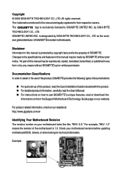
...to their respective owners. For example, "REV: 1.0" means the revision of GIGABYTE branded motherboards. The trademarks mentioned in this manual may be made by any form or by GIGABYTE without GIGABYTE's prior written permission. is 1.0. Changes to assist in this manual is ...of this : "REV: X.X." For product-related information, check on our website at: http://www.gigabyte.com.tw Identifying Your Motherboard Revision The revision number on how to GIGABYTE UNITED INC. Example: Documentation Classifications In order to the specifications and features in the use...
...to their respective owners. For example, "REV: 1.0" means the revision of GIGABYTE branded motherboards. The trademarks mentioned in this manual may be made by any form or by GIGABYTE without GIGABYTE's prior written permission. is 1.0. Changes to assist in this manual is ...of this : "REV: X.X." For product-related information, check on our website at: http://www.gigabyte.com.tw Identifying Your Motherboard Revision The revision number on how to GIGABYTE UNITED INC. Example: Documentation Classifications In order to the specifications and features in the use...
Manual
Page 4
Table of Contents Box Contents ...6 OptionalItems ...6 GA-EX38-DS4 Motherboard Layout 7 Block Diagram ...8 Chapter 1 Hardware Installation 9 1-1 Installation Precautions 9 1-2 Product Specifications 10 1-3 Installing the CPU and CPU Cooler 13 1-3-1 Installing the CPU 13 1-3-2 Installing the CPU ...
Table of Contents Box Contents ...6 OptionalItems ...6 GA-EX38-DS4 Motherboard Layout 7 Block Diagram ...8 Chapter 1 Hardware Installation 9 1-1 Installation Precautions 9 1-2 Product Specifications 10 1-3 Installing the CPU and CPU Cooler 13 1-3-1 Installing the CPU 13 1-3-2 Installing the CPU ...
Manual
Page 6
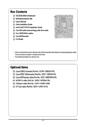
.... 12CR1-1SPDIN-01R) COM port cable (Part No. 12CF1-1CM001-32R) LPT port cable (Part No. 12CF1-1LP001-01R) - 6 - Box Contents GA-EX38-DS4 motherboard Motherboard driver disk User's Manual Quick Installation Guide Intel® LGA775 CPU Installation Guide One IDE cable and one floppy disk drive cable Four SATA 3Gb.../s cables One SATA bracket I/O Shield • The box contents above are subject to change without notice. • The motherboard image is for reference only and the actual items shall depend on product package you obtain. The box contents are for reference only.
.... 12CR1-1SPDIN-01R) COM port cable (Part No. 12CF1-1CM001-32R) LPT port cable (Part No. 12CF1-1LP001-01R) - 6 - Box Contents GA-EX38-DS4 motherboard Motherboard driver disk User's Manual Quick Installation Guide Intel® LGA775 CPU Installation Guide One IDE cable and one floppy disk drive cable Four SATA 3Gb.../s cables One SATA bracket I/O Shield • The box contents above are subject to change without notice. • The motherboard image is for reference only and the actual items shall depend on product package you obtain. The box contents are for reference only.

Manual
Page 7
GA-EX38-DS4 Motherboard Layout KB_MS RCA_SPDIF USB_1394_1 SYS_FAN1 ATX_12V_2X LGA775 CPU_FAN PHASE LED ATX USB_1394_2 USB_LAN1 USB_LAN2 AUDIO RTL8111B F_AUDIO PCIE_1 NB_FAN RTL8111B CODEC CD_IN PCIE_16_1 PCIE_2 PCIE_3 BP_BIOS MAIN_BIOS PCIE_16_2 Intel® X38 GA-EX38-DS4 BAT CLR_CMOS Intel® ICH9R DDRII1 DDRII2 DDRII3 DDRII4 PWR_FAN FDD SATAII0 IDE SATAII1 SPDIF_O PCI1 IT8718 PCI2 LPT CI COM TPM F_1394 F_USB2 F_USB1 TSB43AB23 GIGABYTE SATA2 SATAII4 PWR_LED SATAII2 SATAII3 SPDIF_IN SYS_FAN2 F_PANEL SATAII5 - 7 -
GA-EX38-DS4 Motherboard Layout KB_MS RCA_SPDIF USB_1394_1 SYS_FAN1 ATX_12V_2X LGA775 CPU_FAN PHASE LED ATX USB_1394_2 USB_LAN1 USB_LAN2 AUDIO RTL8111B F_AUDIO PCIE_1 NB_FAN RTL8111B CODEC CD_IN PCIE_16_1 PCIE_2 PCIE_3 BP_BIOS MAIN_BIOS PCIE_16_2 Intel® X38 GA-EX38-DS4 BAT CLR_CMOS Intel® ICH9R DDRII1 DDRII2 DDRII3 DDRII4 PWR_FAN FDD SATAII0 IDE SATAII1 SPDIF_O PCI1 IT8718 PCI2 LPT CI COM TPM F_1394 F_USB2 F_USB1 TSB43AB23 GIGABYTE SATA2 SATAII4 PWR_LED SATAII2 SATAII3 SPDIF_IN SYS_FAN2 F_PANEL SATAII5 - 7 -

Manual
Page 9
... have an ESD wrist strap, keep your hands dry and first touch a metal object to eliminate static electricity. • Prior to installing the motherboard, please have a problem related to wear an electrostatic discharge (ESD) wrist strap when handling electronic components such as a result of the product, ...system components as well as physical harm to the user. • If you are connected tightly and securely. • When handling the motherboard, avoid touching any installation steps or have it on top of an antistatic pad or within an electrostatic shielding container. • Before ...
... have an ESD wrist strap, keep your hands dry and first touch a metal object to eliminate static electricity. • Prior to installing the motherboard, please have a problem related to wear an electrostatic discharge (ESD) wrist strap when handling electronic components such as a result of the product, ...system components as well as physical harm to the user. • If you are connected tightly and securely. • When handling the motherboard, avoid touching any installation steps or have it on top of an antistatic pad or within an electrostatic shielding container. • Before ...
Manual
Page 10
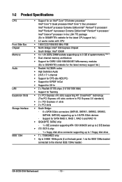
... memory (Note 1) Š Dual channel memory architecture Š Support for DDR2 1200/1066/800/667 MHz memory modules (Go to GIGABYTE's website for the latest memory support list.) Š Realtek ALC889A codec Š High Definition Audio Š 2/4/5.1/7.1-channel Š Support...Š South Bridge: - 6 x SATA 3Gb/s connectors (SATAII0, SATAII1, SATAII2, SATAII3, SATAII4, SATAII5) supporting up to the internal IEEE 1394a header) GA-EX38-DS4 Motherboard - 10 - TSB43AB23 chip Š Up to 3 IEEE 1394a ports (2 on the back panel, 1 via the IEEE 1394a bracket connected to 1 floppy disk...
... memory (Note 1) Š Dual channel memory architecture Š Support for DDR2 1200/1066/800/667 MHz memory modules (Go to GIGABYTE's website for the latest memory support list.) Š Realtek ALC889A codec Š High Definition Audio Š 2/4/5.1/7.1-channel Š Support...Š South Bridge: - 6 x SATA 3Gb/s connectors (SATAII0, SATAII1, SATAII2, SATAII3, SATAII4, SATAII5) supporting up to the internal IEEE 1394a header) GA-EX38-DS4 Motherboard - 10 - TSB43AB23 chip Š Up to 3 IEEE 1394a ports (2 on the back panel, 1 via the IEEE 1394a bracket connected to 1 floppy disk...
Manual
Page 12
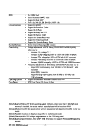
... adjustments in BIOS Setup (CPU/DDR2/PCIe/FSB/(G)MCH) allow you install. (Note 3) Available functions in Easytune may differ by motherboard model. (Note 4) The adjustable CPU voltage range depends on the CPU being used. (Note 5) Due to chipset limitation, Intel ICH9R RAID driver does not support Windows 2000 operating system. GA-EX38-DS4 Motherboard - 12 -
... adjustments in BIOS Setup (CPU/DDR2/PCIe/FSB/(G)MCH) allow you install. (Note 3) Available functions in Easytune may differ by motherboard model. (Note 4) The adjustable CPU voltage range depends on the CPU being used. (Note 5) Due to chipset limitation, Intel ICH9R RAID driver does not support Windows 2000 operating system. GA-EX38-DS4 Motherboard - 12 -

Manual
Page 13
...latest CPU support list.) • Always turn on the computer if the CPU cooler is not recom- Locate the alignment keys on the motherboard CPU socket and the notches on the CPU - 13 - It is not installed, otherwise overheating and damage of the CPU may occur... your hardware specifications including the CPU, graphics card, memory, hard drive, etc. 1-3-1 Installing the CPU A. mended that the motherboard supports the CPU. (Go to GIGABYTE's website for the peripherals. 1-3 Installing the CPU and CPU Cooler Read the following guidelines before installing the CPU to prevent hardware...
...latest CPU support list.) • Always turn on the computer if the CPU cooler is not recom- Locate the alignment keys on the motherboard CPU socket and the notches on the CPU - 13 - It is not installed, otherwise overheating and damage of the CPU may occur... your hardware specifications including the CPU, graphics card, memory, hard drive, etc. 1-3-1 Installing the CPU A. mended that the motherboard supports the CPU. (Go to GIGABYTE's website for the peripherals. 1-3 Installing the CPU and CPU Cooler Read the following guidelines before installing the CPU to prevent hardware...
Manual
Page 14
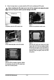
... the motherboard CPU socket. Step 2: Remove the protective socket cover. Step 3: Lift the metal load plate on the CPU socket. B. Before installing the CPU, make sure to turn off the computer and unplug the power cord from the power outlet to prevent damage to correctly install the CPU into position. GA-EX38-DS4 Motherboard - 14...
... the motherboard CPU socket. Step 2: Remove the protective socket cover. Step 3: Lift the metal load plate on the CPU socket. B. Before installing the CPU, make sure to turn off the computer and unplug the power cord from the power outlet to prevent damage to correctly install the CPU into position. GA-EX38-DS4 Motherboard - 14...

Manual
Page 15
... pins through the pin holes on the contrary, is complete. Inadequately removing the CPU cooler may adhere to correctly install the CPU cooler on the motherboard. (The following procedure uses Intel® boxed cooler as the picture above, the installation is to the CPU fan header (CPU_FAN) on the...grease/tape between the CPU cooler and CPU may damage the CPU. - 15 - Step 4: You should hear a "click" when pushing down on the motherboard. Check that the Male and Female push pins are joined closely. (Refer to your CPU cooler installation manual for instructions on the surface of the...
... pins through the pin holes on the contrary, is complete. Inadequately removing the CPU cooler may adhere to correctly install the CPU cooler on the motherboard. (The following procedure uses Intel® boxed cooler as the picture above, the installation is to the CPU fan header (CPU_FAN) on the...grease/tape between the CPU cooler and CPU may damage the CPU. - 15 - Step 4: You should hear a "click" when pushing down on the motherboard. Check that the Male and Female push pins are joined closely. (Refer to your CPU cooler installation manual for instructions on the surface of the...
Manual
Page 16
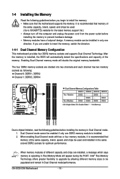
After the memory is installed. 2. DS/SS - - DS/SS - - Dual Channel mode cannot be used . (Go to GIGABYTE's website for optimum performance. When enabling Dual Channel mode with two or four memory modules, it is recommended that memory of the same capacity, ... four DDR2 memory sockets and supports Dual Channel Technology. Enabling Dual Channel memory mode will double the original memory bandwidth. GA-EX38-DS4 Motherboard - 16 - It is operating in Flex Memory Mode will automatically detect the specifications and capacity of the same capacity, brand, speed, and chips be...
After the memory is installed. 2. DS/SS - - DS/SS - - Dual Channel mode cannot be used . (Go to GIGABYTE's website for optimum performance. When enabling Dual Channel mode with two or four memory modules, it is recommended that memory of the same capacity, ... four DDR2 memory sockets and supports Dual Channel Technology. Enabling Dual Channel memory mode will double the original memory bandwidth. GA-EX38-DS4 Motherboard - 16 - It is operating in Flex Memory Mode will automatically detect the specifications and capacity of the same capacity, brand, speed, and chips be...

Manual
Page 17
... , make sure to turn off the computer and unplug the power cord from the power outlet to prevent damage to install DDR2 DIMMs on this motherboard. DDR2 DIMMs are not compatible to DDR DIMMs. Be sure to the memory module.
... , make sure to turn off the computer and unplug the power cord from the power outlet to prevent damage to install DDR2 DIMMs on this motherboard. DDR2 DIMMs are not compatible to DDR DIMMs. Be sure to the memory module.
Manual
Page 18
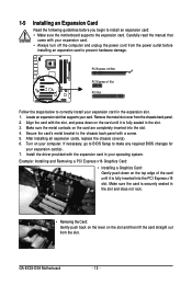
...; Installing a Graphics Card: Gently push down on the top edge of the card until it is fully seated in the expansion slot. 1. GA-EX38-DS4 Motherboard - 18 - PCI Express x16 Slot PCI Express x1 Slot PCI Slot Follow the steps below to correctly install your operating system. If necessary,... go to BIOS Setup to install an expansion card: • Make sure the motherboard supports the expansion card. Remove the metal slot cover from the slot. Locate an expansion slot that came with the slot, and ...
...; Installing a Graphics Card: Gently push down on the top edge of the card until it is fully seated in the expansion slot. 1. GA-EX38-DS4 Motherboard - 18 - PCI Express x16 Slot PCI Express x1 Slot PCI Slot Follow the steps below to correctly install your operating system. If necessary,... go to BIOS Setup to install an expansion card: • Make sure the motherboard supports the expansion card. Remove the metal slot cover from the slot. Locate an expansion slot that came with the slot, and ...

Manual
Page 19
... cable. Connect the other ends of the cable from the bracket to the SATA port on your SATA device. Follow the steps below to your motherboard. nector on Step 5: the bracket. Step 3: Step 4: Connect the power Plug one end of the SATA signal cable and SATA power cable to install the...
... cable. Connect the other ends of the cable from the bracket to the SATA port on your SATA device. Follow the steps below to your motherboard. nector on Step 5: the bracket. Step 3: Step 4: Connect the power Plug one end of the SATA signal cable and SATA power cable to install the...
Manual
Page 20
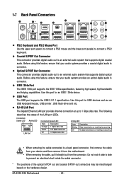
Use this feature, ensure that your device and then remove it from the motherboard. • When removing the cable, pull it side to side to an external audio system that supports digital optical audio. Coaxial S/PDIF Out ... out connectors may be interchanged based on the hardware design. Use this feature, ensure that your audio system provides an optical digital audio in connector. GA-EX38-DS4 Motherboard - 20 - Optical S/PDIF Out Connector This connector provides digital audio out to a back panel connector, first remove the cable from your audio system provides...
Use this feature, ensure that your device and then remove it from the motherboard. • When removing the cable, pull it side to side to an external audio system that supports digital optical audio. Coaxial S/PDIF Out ... out connectors may be interchanged based on the hardware design. Use this feature, ensure that your audio system provides an optical digital audio in connector. GA-EX38-DS4 Motherboard - 20 - Optical S/PDIF Out Connector This connector provides digital audio out to a back panel connector, first remove the cable from your audio system provides...

Manual
Page 22
... sure to the connector on the motherboard. Unplug the power cord from the power outlet to prevent damage to the devices. • After installing the device and before connecting external devices: • First make sure the device cable has been securely attached to turn off the devices and your computer. GA-EX38-DS4 Motherboard - 22 -
... sure to the connector on the motherboard. Unplug the power cord from the power outlet to prevent damage to the devices. • After installing the device and before connecting external devices: • First make sure the device cable has been securely attached to turn off the devices and your computer. GA-EX38-DS4 Motherboard - 22 -

Manual
Page 23
... power supply providing a 2x4 12V and power connector, remove the protective covers from the 12V power connector and the main power connector on the motherboard. Hardware Installation 1/2) ATX_12V_2X/ATX (2x4 12V Power Connector and 2x12 Main Power Connector) With the use of a power supply providing a 2x4... power supplies with 2x2 12V power connector. The main power connector is turned off and all the components on the motherboard. When using a power supply providing a 2x2 12V power connector. 8 4 5 1 ATX_12V_2X ATX_12V_2X: Pin No. The power connector possesses a foolproof...
... power supply providing a 2x4 12V and power connector, remove the protective covers from the 12V power connector and the main power connector on the motherboard. Hardware Installation 1/2) ATX_12V_2X/ATX (2x4 12V Power Connector and 2x12 Main Power Connector) With the use of a power supply providing a 2x4... power supplies with 2x2 12V power connector. The main power connector is turned off and all the components on the motherboard. When using a power supply providing a 2x2 12V power connector. 8 4 5 1 ATX_12V_2X ATX_12V_2X: Pin No. The power connector possesses a foolproof...

Manual
Page 24
... from overheating. CPU_FAN: Pin No. Overheating may hang. • These fan headers are not configuration jumper blocks. GA-EX38-DS4 Motherboard - 24 - Definition 1 1 GND SYS_FAN2 2 Speed Control 3 Sense 4 +5V SYS_FAN1/PWR_FAN: Pin No. The black connector wire ...power voltage and possesses a foolproof insertion design. For optimum heat dissipation, it in the correct orientation. 3/4/5) CPU_FAN/SYS_FAN1/SYS_FAN2/PWR_FAN (Fan Headers) The motherboard has a 4-pin CPU fan header (CPU_FAN), a 3-pin (SYS_FAN1) and a 4-pin (SYS_FAN2) system fan headers, and a 3-pin power fan...
... from overheating. CPU_FAN: Pin No. Overheating may hang. • These fan headers are not configuration jumper blocks. GA-EX38-DS4 Motherboard - 24 - Definition 1 1 GND SYS_FAN2 2 Speed Control 3 Sense 4 +5V SYS_FAN1/PWR_FAN: Pin No. The black connector wire ...power voltage and possesses a foolproof insertion design. For optimum heat dissipation, it in the correct orientation. 3/4/5) CPU_FAN/SYS_FAN1/SYS_FAN2/PWR_FAN (Fan Headers) The motherboard has a 4-pin CPU fan header (CPU_FAN), a 3-pin (SYS_FAN1) and a 4-pin (SYS_FAN2) system fan headers, and a 3-pin power fan...


