Manual
Page 1
GA-EX38-DS4 LGA775 socket motherboard for Intel® CoreTM processor family/ Intel® Pentium® processor family/Intel® Celeron® processor family User's Manual Rev. 1101 12ME-EX38DS4-1101R
GA-EX38-DS4 LGA775 socket motherboard for Intel® CoreTM processor family/ Intel® Pentium® processor family/Intel® Celeron® processor family User's Manual Rev. 1101 12ME-EX38DS4-1101R
Manual
Page 2
Motherboard GA-EX38-DS4 Jan. 16, 2008 Motherboard GA-EX38-DS4 Jan. 16, 2008
Motherboard GA-EX38-DS4 Jan. 16, 2008 Motherboard GA-EX38-DS4 Jan. 16, 2008
Manual
Page 4
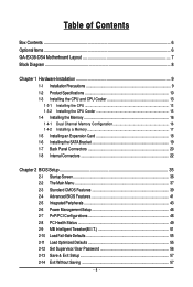
Table of Contents Box Contents ...6 OptionalItems ...6 GA-EX38-DS4 Motherboard Layout 7 Block Diagram ...8 Chapter 1 Hardware Installation 9 1-1 Installation Precautions 9 1-2 Product Specifications 10 1-3 Installing the CPU and CPU Cooler 13 1-3-1 Installing the CPU 13 1-3-2 Installing the ...
Table of Contents Box Contents ...6 OptionalItems ...6 GA-EX38-DS4 Motherboard Layout 7 Block Diagram ...8 Chapter 1 Hardware Installation 9 1-1 Installation Precautions 9 1-2 Product Specifications 10 1-3 Installing the CPU and CPU Cooler 13 1-3-1 Installing the CPU 13 1-3-2 Installing the ...
Manual
Page 6
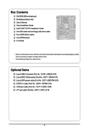
Box Contents GA-EX38-DS4 motherboard Motherboard driver disk User's Manual Quick Installation Guide Intel® LGA775 CPU Installation Guide One IDE cable and one floppy disk drive cable Four ...
Box Contents GA-EX38-DS4 motherboard Motherboard driver disk User's Manual Quick Installation Guide Intel® LGA775 CPU Installation Guide One IDE cable and one floppy disk drive cable Four ...

Manual
Page 7
GA-EX38-DS4 Motherboard Layout KB_MS RCA_SPDIF USB_1394_1 SYS_FAN1 ATX_12V_2X LGA775 CPU_FAN PHASE LED ATX USB_1394_2 USB_LAN1 USB_LAN2 AUDIO RTL8111B F_AUDIO PCIE_1 NB_FAN RTL8111B CODEC CD_IN PCIE_16_1 PCIE_2 PCIE_3 BP_BIOS MAIN_BIOS PCIE_16_2 Intel® X38 GA-EX38-DS4 BAT CLR_CMOS Intel® ICH9R DDRII1 DDRII2 DDRII3 DDRII4 PWR_FAN FDD SATAII0 IDE SATAII1 SPDIF_O PCI1 IT8718 PCI2 LPT CI COM TPM F_1394 F_USB2 F_USB1 TSB43AB23 GIGABYTE SATA2 SATAII4 PWR_LED SATAII2 SATAII3 SPDIF_IN SYS_FAN2 F_PANEL SATAII5 - 7 -
GA-EX38-DS4 Motherboard Layout KB_MS RCA_SPDIF USB_1394_1 SYS_FAN1 ATX_12V_2X LGA775 CPU_FAN PHASE LED ATX USB_1394_2 USB_LAN1 USB_LAN2 AUDIO RTL8111B F_AUDIO PCIE_1 NB_FAN RTL8111B CODEC CD_IN PCIE_16_1 PCIE_2 PCIE_3 BP_BIOS MAIN_BIOS PCIE_16_2 Intel® X38 GA-EX38-DS4 BAT CLR_CMOS Intel® ICH9R DDRII1 DDRII2 DDRII3 DDRII4 PWR_FAN FDD SATAII0 IDE SATAII1 SPDIF_O PCI1 IT8718 PCI2 LPT CI COM TPM F_1394 F_USB2 F_USB1 TSB43AB23 GIGABYTE SATA2 SATAII4 PWR_LED SATAII2 SATAII3 SPDIF_IN SYS_FAN2 F_PANEL SATAII5 - 7 -
Manual
Page 10
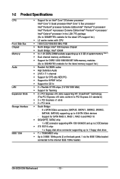
... Bridge: - 6 x SATA 3Gb/s connectors (SATAII0, SATAII1, SATAII2, SATAII3, SATAII4, SATAII5) supporting up to the internal IEEE 1394a header) GA-EX38-DS4 Motherboard - 10 - 1-2 Product Specifications CPU Front Side Bus Chipset Memory Audio LAN Expansion Slots Storage Interface IEEE 1394 Š Support for an Intel... memory (Note 1) Š Dual channel memory architecture Š Support for DDR2 1200/1066/800/667 MHz memory modules (Go to GIGABYTE's website for the latest memory support list.) Š Realtek ALC889A codec Š High Definition Audio Š 2/4/5.1/7.1-channel Š Support...
... Bridge: - 6 x SATA 3Gb/s connectors (SATAII0, SATAII1, SATAII2, SATAII3, SATAII4, SATAII5) supporting up to the internal IEEE 1394a header) GA-EX38-DS4 Motherboard - 10 - 1-2 Product Specifications CPU Front Side Bus Chipset Memory Audio LAN Expansion Slots Storage Interface IEEE 1394 Š Support for an Intel... memory (Note 1) Š Dual channel memory architecture Š Support for DDR2 1200/1066/800/667 MHz memory modules (Go to GIGABYTE's website for the latest memory support list.) Š Realtek ALC889A codec Š High Definition Audio Š 2/4/5.1/7.1-channel Š Support...
Manual
Page 12
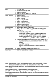
... CPU voltage (Note 4) - Increase PCIe voltage by 0.05V to chipset limitation, Intel ICH9R RAID driver does not support Windows 2000 operating system. Adjust DDR2 frequency - GA-EX38-DS4 Motherboard - 12 - Adjust PCI Express frequency from 100 MHz to : - Increase DDR2 voltage by 0.025V to 0.775V with 1 MHz increment -
... CPU voltage (Note 4) - Increase PCIe voltage by 0.05V to chipset limitation, Intel ICH9R RAID driver does not support Windows 2000 operating system. Adjust DDR2 frequency - GA-EX38-DS4 Motherboard - 12 - Adjust PCI Express frequency from 100 MHz to : - Increase DDR2 voltage by 0.025V to 0.775V with 1 MHz increment -
Manual
Page 14
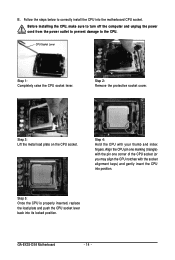
... off the computer and unplug the power cord from the power outlet to prevent damage to correctly install the CPU into the motherboard CPU socket. GA-EX38-DS4 Motherboard - 14 - Step 5: Once the CPU is properly inserted, replace the load plate and push the CPU socket lever back into position. Step 2: Remove the...
... off the computer and unplug the power cord from the power outlet to prevent damage to correctly install the CPU into the motherboard CPU socket. GA-EX38-DS4 Motherboard - 14 - Step 5: Once the CPU is properly inserted, replace the load plate and push the CPU socket lever back into position. Step 2: Remove the...
Manual
Page 16
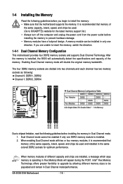
... memory to prevent hardware damage. • Memory modules have a foolproof design. A memory module can be used . (Go to GIGABYTE's website for optimum performance. Four Modules DS/SS DS/SS DS/SS DDRII4 - GA-EX38-DS4 Motherboard - 16 - After the memory is recommended that the motherboard supports the memory. Dual Channel mode cannot be populated...
... memory to prevent hardware damage. • Memory modules have a foolproof design. A memory module can be used . (Go to GIGABYTE's website for optimum performance. Four Modules DS/SS DS/SS DS/SS DDRII4 - GA-EX38-DS4 Motherboard - 16 - After the memory is recommended that the motherboard supports the memory. Dual Channel mode cannot be populated...
Manual
Page 18
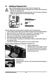
... unplug the power cord from the power outlet before you begin to install an expansion card: • Make sure the motherboard supports the expansion card. GA-EX38-DS4 Motherboard - 18 - Align the card with the expansion card in the expansion slot. 1. If necessary, go to BIOS Setup to make any required BIOS changes...
... unplug the power cord from the power outlet before you begin to install an expansion card: • Make sure the motherboard supports the expansion card. GA-EX38-DS4 Motherboard - 18 - Align the card with the expansion card in the expansion slot. 1. If necessary, go to BIOS Setup to make any required BIOS changes...
Manual
Page 20
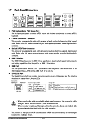
... system that your device and then remove it from the motherboard. • When removing the cable, pull it side to side to connect a PS/2 keyboard. GA-EX38-DS4 Motherboard - 20 - Before using this port for USB devices such as an USB keyboard/mouse, USB printer, USB flash drive and etc. Use this feature...
... system that your device and then remove it from the motherboard. • When removing the cable, pull it side to side to connect a PS/2 keyboard. GA-EX38-DS4 Motherboard - 20 - Before using this port for USB devices such as an USB keyboard/mouse, USB printer, USB flash drive and etc. Use this feature...

Manual
Page 22
... device and before connecting external devices: • First make sure the device cable has been securely attached to turn off the devices and your computer. GA-EX38-DS4 Motherboard - 22 - 1-8 Internal Connectors 4 1 3 23 2 7 6 12 5 22 24 9 13 15 8 21 10 18 14 19 20 4 17 16 11 9 1) ATX_12V_2X 2) ATX 3) CPU_FAN 4) SYS_FAN1/SYS_FAN2 5) PWR_FAN...
... device and before connecting external devices: • First make sure the device cable has been securely attached to turn off the devices and your computer. GA-EX38-DS4 Motherboard - 22 - 1-8 Internal Connectors 4 1 3 23 2 7 6 12 5 22 24 9 13 15 8 21 10 18 14 19 20 4 17 16 11 9 1) ATX_12V_2X 2) ATX 3) CPU_FAN 4) SYS_FAN1/SYS_FAN2 5) PWR_FAN...

Manual
Page 24
... cap on the headers. The fan header has a foolproof insertion design. Most fans are not configuration jumper blocks. Overheating may result in the correct orientation. GA-EX38-DS4 Motherboard - 24 - When connecting a fan cable, be installed inside the chassis. The motherboard supports CPU fan speed control, which requires the use of a CPU fan...
... cap on the headers. The fan header has a foolproof insertion design. Most fans are not configuration jumper blocks. Overheating may result in the correct orientation. GA-EX38-DS4 Motherboard - 24 - When connecting a fan cable, be installed inside the chassis. The motherboard supports CPU fan speed control, which requires the use of a CPU fan...

Manual
Page 26
... powered off when the system is operating. Each SATA connector supports a single SATA device. System Status LED S0 On S1 Blinking S3/S4/S5 Off GA-EX38-DS4 Motherboard - 26 - 9) SATAII0/1/2/3/4/5 (SATA 3Gb/s Connectors) The SATA connectors conform to SATA 3Gb/s standard and are to be an even number.) • A RAID 10 configuration...
... powered off when the system is operating. Each SATA connector supports a single SATA device. System Status LED S0 On S1 Blinking S3/S4/S5 Off GA-EX38-DS4 Motherboard - 26 - 9) SATAII0/1/2/3/4/5 (SATA 3Gb/s Connectors) The SATA connectors conform to SATA 3Gb/s standard and are to be an even number.) • A RAID 10 configuration...
Manual
Page 28
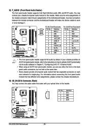
... provides an AC'97 front panel audio module, refer to the instructions on how to work or even damage it. Definition 1 CD-L 2 GND 3 GND 4 CD-R GA-EX38-DS4 Motherboard - 28 - For HD Front Panel Audio: For AC'97 Front Panel Audio: 10 9 Pin No. Definition 1 MIC2_L Pin No. 1 Definition MIC 2 1 2 3 GND MIC2_R 2 GND...
... provides an AC'97 front panel audio module, refer to the instructions on how to work or even damage it. Definition 1 CD-L 2 GND 3 GND 4 CD-R GA-EX38-DS4 Motherboard - 28 - For HD Front Panel Audio: For AC'97 Front Panel Audio: 10 9 Pin No. Definition 1 MIC2_L Pin No. 1 Definition MIC 2 1 2 3 GND MIC2_R 2 GND...

Manual
Page 30
GA-EX38-DS4 Motherboard - 30 - Each USB header can provide one end of the device cable to your computer and then attach the other end of the cable ...
GA-EX38-DS4 Motherboard - 30 - Each USB header can provide one end of the device cable to your computer and then attach the other end of the cable ...

Manual
Page 32
Definition 1 1 Signal 2 GND GA-EX38-DS4 Motherboard - 32 - Pin No. This function requires a chassis with chassis intrusion detection design. 20) COM (Serial Port Header) The COM header can provide one serial port via an optional COM port cable. For purchasing the optional COM port cable, please contact the local dealer. 2 10 1 9 Pin No. 1 2 3 4 5 6 7 8 9 10 Definition NDCD NSIN NSOUT NDTR GND NDSR NRTS NCTS NRI No Pin 21) CI (Chassis Intrusion Header) This motherboard provides a chassis detection feature that detects if the chassis cover has been removed.
Definition 1 1 Signal 2 GND GA-EX38-DS4 Motherboard - 32 - Pin No. This function requires a chassis with chassis intrusion detection design. 20) COM (Serial Port Header) The COM header can provide one serial port via an optional COM port cable. For purchasing the optional COM port cable, please contact the local dealer. 2 10 1 9 Pin No. 1 2 3 4 5 6 7 8 9 10 Definition NDCD NSIN NSOUT NDTR GND NDSR NRTS NCTS NRI No Pin 21) CI (Chassis Intrusion Header) This motherboard provides a chassis detection feature that detects if the chassis cover has been removed.
Manual
Page 34
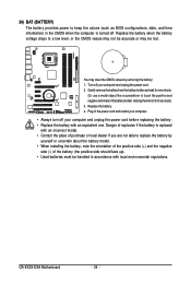
GA-EX38-DS4 Motherboard - 34 - Replace the battery. 4. Plug in the power cord and restart your computer. • Always turn off your computer and unplug the power cord. 2. ...
GA-EX38-DS4 Motherboard - 34 - Replace the battery. 4. Plug in the power cord and restart your computer. • Always turn off your computer and unplug the power cord. 2. ...

Manual
Page 36
..., Inc. Note: The setting in BIOS Setup. : Xpress Recovery2 If you to set the first boot device without having to XpressRecovery2 during the POST. EX38-DS4 F1a . . . . : BIOS Setup : XpressRecovery2 : Boot Menu : Qflash 01/02/2008-X38-ICH9-6A89OG0WC-00 Function Keys Function Keys: : ...To exit Boot Menu, press . The LOGO Screen (Default) : POST Screen : BIOS Setup/Q-Flash : XpressRecovery2 : Boot Menu: Qflash Function Keys B. GA-EX38-DS4 Motherboard - 36 - To show the BIOS POST screen. In Boot Menu, use the up hard drive data using the motherboard driver disk, the key...
..., Inc. Note: The setting in BIOS Setup. : Xpress Recovery2 If you to set the first boot device without having to XpressRecovery2 during the POST. EX38-DS4 F1a . . . . : BIOS Setup : XpressRecovery2 : Boot Menu : Qflash 01/02/2008-X38-ICH9-6A89OG0WC-00 Function Keys Function Keys: : ...To exit Boot Menu, press . The LOGO Screen (Default) : POST Screen : BIOS Setup/Q-Flash : XpressRecovery2 : Boot Menu: Qflash Function Keys B. GA-EX38-DS4 Motherboard - 36 - To show the BIOS POST screen. In Boot Menu, use the up hard drive data using the motherboard driver disk, the key...

Manual
Page 38
... system operations. „ Set Supervisor Password Change, set , or disable password. First enter the profile name (to erase the default profile name, use this task.) GA-EX38-DS4 Motherboard - 38 - Pressing to the confirmation message will exit BIOS Setup. (Pressing can also carry out this function to load the BIOS settings from BIOS...
... system operations. „ Set Supervisor Password Change, set , or disable password. First enter the profile name (to erase the default profile name, use this task.) GA-EX38-DS4 Motherboard - 38 - Pressing to the confirmation message will exit BIOS Setup. (Pressing can also carry out this function to load the BIOS settings from BIOS...

