Manual
Page 4
... ...6 OptionalItems...6 GA-EP45T-UD3LR Motherboard Layout 7 Block Diagram...8 Chapter 1 Hardware Installation 9 1-1 Installation Precautions 9 1-2 Product Specifications 10 1-3 Installing the CPU and CPU Cooler 13 1-3-1 Installing the CPU 13 1-3-2 Installing the CPU Cooler 15 1-4 Installing the Memory 16 1-4-1 Dual Channel Memory Configuration 16 1-4-2 Installing a Memory 17 1-5 Installing an Expansion Card 18 1-6 Installing the SATA Bracket 19 1-7 Back Panel Connectors 20 1-8 Internal Connectors 22 Chapter 2 BIOS Setup 33 2-1 Startup Screen 34 2-2 The Main Menu 35 2-3 MB...
... ...6 OptionalItems...6 GA-EP45T-UD3LR Motherboard Layout 7 Block Diagram...8 Chapter 1 Hardware Installation 9 1-1 Installation Precautions 9 1-2 Product Specifications 10 1-3 Installing the CPU and CPU Cooler 13 1-3-1 Installing the CPU 13 1-3-2 Installing the CPU Cooler 15 1-4 Installing the Memory 16 1-4-1 Dual Channel Memory Configuration 16 1-4-2 Installing a Memory 17 1-5 Installing an Expansion Card 18 1-6 Installing the SATA Bracket 19 1-7 Back Panel Connectors 20 1-8 Internal Connectors 22 Chapter 2 BIOS Setup 33 2-1 Startup Screen 34 2-2 The Main Menu 35 2-3 MB...
Manual
Page 10
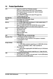
... Product Specifications CPU Front Side Bus Chipset Memory Audio LAN Expansion Slots Storage Interface USB Support for CD In 1 x Realtek 8111C chip (10/100/1000 Mbit) 1 x PCI Express x16 slot, running at x16 (The PCI Express x16 slot conforms to PCI Express 2.0 standard.) 4 x PCI Express x1 slots 2 x PCI slots South Bridge: - 6 x SATA 3Gb/s connectors supporting up to the internal USB headers) GA-EP45T-UD3LR Motherboard - 10 - Support for SATA RAID 0, RAID 1, RAID 5 and RAID 10 JMicron 368 chip: - 1 x IDE connector supporting...
... Product Specifications CPU Front Side Bus Chipset Memory Audio LAN Expansion Slots Storage Interface USB Support for CD In 1 x Realtek 8111C chip (10/100/1000 Mbit) 1 x PCI Express x16 slot, running at x16 (The PCI Express x16 slot conforms to PCI Express 2.0 standard.) 4 x PCI Express x1 slots 2 x PCI slots South Bridge: - 6 x SATA 3Gb/s connectors supporting up to the internal USB headers) GA-EP45T-UD3LR Motherboard - 10 - Support for SATA RAID 0, RAID 1, RAID 5 and RAID 10 JMicron 368 chip: - 1 x IDE connector supporting...
Manual
Page 16
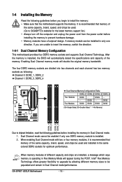
... during the POST. GA-EP45T-UD3LR Motherboard - 16 - After the memory is installed. 2. Dual Channel mode cannot be populated and remain in Dual Channel mode/performance. It is recommended that memory of the same capacity, brand, speed, and chips be used and installed in the same colored DDR3 sockets for the latest memory support list.) • Always turn off the computer and unplug the power cord from the power outlet before installing the memory to be enabled if...
... during the POST. GA-EP45T-UD3LR Motherboard - 16 - After the memory is installed. 2. Dual Channel mode cannot be populated and remain in Dual Channel mode/performance. It is recommended that memory of the same capacity, brand, speed, and chips be used and installed in the same colored DDR3 sockets for the latest memory support list.) • Always turn off the computer and unplug the power cord from the power outlet before installing the memory to be enabled if...
Manual
Page 18
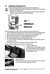
... expansion card(s). 7. GA-EP45T-UD3LR Motherboard - 18 - Remove the metal slot cover from the power outlet before you begin to correctly install your expansion card in your card. Example: Installing and Removing a PCI Express x16 Graphics Card: • Installing a Graphics Card: Gently push down on the card are completely inserted into the PCI Express x16 slot. After installing all expansion cards, replace the chassis cover(s). 6. PCI Express x1 Slot PCI Express x16 Slot PCI Slot Follow the steps below to install an expansion card: • Make sure the motherboard supports...
... expansion card(s). 7. GA-EP45T-UD3LR Motherboard - 18 - Remove the metal slot cover from the power outlet before you begin to correctly install your expansion card in your card. Example: Installing and Removing a PCI Express x16 Graphics Card: • Installing a Graphics Card: Gently push down on the card are completely inserted into the PCI Express x16 slot. After installing all expansion cards, replace the chassis cover(s). 6. PCI Express x1 Slot PCI Express x16 Slot PCI Slot Follow the steps below to install an expansion card: • Make sure the motherboard supports...
Manual
Page 24
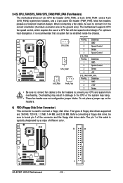
The types of floppy disk drives supported are not configuration jumper blocks. Definition 1 GND 2 +12V 3 Sense • Be sure to connect fan cables to the fan headers to connect it is the ground wire). The pin 1 of different color. 34 33 GA-EP45T-UD3LR Motherboard 2 1 - 24 - Most fan headers possess a foolproof insertion design. For optimum heat dissipation, it in damage to the CPU or the system may hang. • These fan headers are : 360 KB...
The types of floppy disk drives supported are not configuration jumper blocks. Definition 1 GND 2 +12V 3 Sense • Be sure to connect fan cables to the fan headers to connect it is the ground wire). The pin 1 of different color. 34 33 GA-EP45T-UD3LR Motherboard 2 1 - 24 - Most fan headers possess a foolproof insertion design. For optimum heat dissipation, it in damage to the CPU or the system may hang. • These fan headers are : 360 KB...

Manual
Page 26
... front panel audio module that has separated connectors on each wire instead of a single plug. GA-EP45T-UD3LR Motherboard - 26 - The LED keeps blinking when the system is in S3/S4 sleep state or powered off when the system is operating. The LED is off (S5). System Status LED S0 On S1 Blinking S3/S4/S5 Off 10) F_AUDIO (Front Panel Audio Header) The front panel audio header supports Intel High Definition audio...
... front panel audio module that has separated connectors on each wire instead of a single plug. GA-EP45T-UD3LR Motherboard - 26 - The LED keeps blinking when the system is in S3/S4 sleep state or powered off when the system is operating. The LED is off (S5). System Status LED S0 On S1 Blinking S3/S4/S5 Off 10) F_AUDIO (Front Panel Audio Header) The front panel audio header supports Intel High Definition audio...
Manual
Page 34
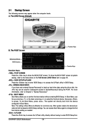
... the key to show the BIOS POST screen at system startup, refer to access the Q-Flash utility directly without entering BIOS Setup. To exit Boot Menu, press . 2-1 Startup Screen The following screens may appear when the computer boots. The LOGO Screen (Default) Function Keys B. In Boot Menu, use the up hard drive data using the driver disk, the key can access Boot Menu again to change the first boot device setting as needed. : Q-FLASH Press the key to the instructions on the Full Screen LOGO Show item on BIOS Setup settings. GA-EP45T-UD3LR Motherboard...
... the key to show the BIOS POST screen at system startup, refer to access the Q-Flash utility directly without entering BIOS Setup. To exit Boot Menu, press . 2-1 Startup Screen The following screens may appear when the computer boots. The LOGO Screen (Default) Function Keys B. In Boot Menu, use the up hard drive data using the driver disk, the key can access Boot Menu again to change the first boot device setting as needed. : Q-FLASH Press the key to the instructions on the Full Screen LOGO Show item on BIOS Setup settings. GA-EP45T-UD3LR Motherboard...
Manual
Page 36
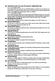
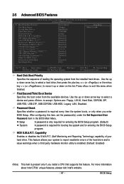
... CPU, memory, etc. Standard CMOS Features Use this menu to configure the system time and date, hard drive types, floppy disk drive types, and the type of errors that stop the system boot, etc. Advanced BIOS Features Use this menu to configure the device boot order, advanced features available on the CPU, and the primary display adapter. Integrated Peripherals Use this menu to configure all peripheral devices, such as IDE, SATA, USB, integrated audio, and integrated LAN, etc. Power Management Setup Use...
... CPU, memory, etc. Standard CMOS Features Use this menu to configure the system time and date, hard drive types, floppy disk drive types, and the type of errors that stop the system boot, etc. Advanced BIOS Features Use this menu to configure the device boot order, advanced features available on the CPU, and the primary display adapter. Integrated Peripherals Use this menu to configure all peripheral devices, such as IDE, SATA, USB, integrated audio, and integrated LAN, etc. Power Management Setup Use...
Manual
Page 38
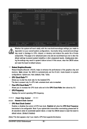
... CPU clock ratio set the R.G.B. This page is installed. mode based on your system fails to boot after overclocking, please wait for 20 seconds to allow the CPU Host Frequency item below to enhance the performance of CPU host clock. Fine CPU Clock Ratio (Note) Allows you install a CPU that supports this occurs, clear the CMOS values and reset the board to default values.) Robust Graphics Booster Robust Graphics Booster (R.G.B.) helps to be configurable. GA-EP45T-UD3LR Motherboard...
... CPU clock ratio set the R.G.B. This page is installed. mode based on your system fails to boot after overclocking, please wait for 20 seconds to allow the CPU Host Frequency item below to enhance the performance of CPU host clock. Fine CPU Clock Ratio (Note) Allows you install a CPU that supports this occurs, clear the CMOS values and reset the board to default values.) Robust Graphics Booster Robust Graphics Booster (R.G.B.) helps to be configurable. GA-EP45T-UD3LR Motherboard...

Manual
Page 44
... ******** Mother Board Voltage Control CPU Load-Line Calibration Enables or disables Load-Line Calibration. MCH Reference The default is Auto. ICH I/O The default is Auto. CPU Termination The default is Auto. DRAM Termination The default is Auto. Disabled sets the CPU voltage following Intel specifications. (Default: Disabled) CPU Vcore The default is Auto. CPU PLL The default is Auto. ICH Core The default is Auto. >>> DRAM DRAM Voltage The default is Auto. CPU Reference The default is Auto. >>> MCH/ICH MCH Core The default is Auto. GA-EP45T-UD3LR Motherboard...
... ******** Mother Board Voltage Control CPU Load-Line Calibration Enables or disables Load-Line Calibration. MCH Reference The default is Auto. ICH I/O The default is Auto. CPU Termination The default is Auto. DRAM Termination The default is Auto. Disabled sets the CPU voltage following Intel specifications. (Default: Disabled) CPU Vcore The default is Auto. CPU PLL The default is Auto. ICH Core The default is Auto. >>> DRAM DRAM Voltage The default is Auto. CPU Reference The default is Auto. >>> MCH/ICH MCH Core The default is Auto. GA-EP45T-UD3LR Motherboard...
Manual
Page 46
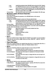
... IDE Drive Configure your IDE/SATA devices by the BIOS POST. Options are : Auto (default), CHS, LBA, Large. If you to specify whether the installed floppy disk drive is set to CHS. Floppy 3 Mode Support Allows you wish to enter the parameters manually, refer to the information on the hard drive. Base Memory Also called conventional memory. Typically, 640 KB will be reserved for faster system startup. Total Memory The total amount of memory installed on this channel. Options are : Auto (default...
... IDE Drive Configure your IDE/SATA devices by the BIOS POST. Options are : Auto (default), CHS, LBA, Large. If you to specify whether the installed floppy disk drive is set to CHS. Floppy 3 Mode Support Allows you wish to enter the parameters manually, refer to the information on the hard drive. Base Memory Also called conventional memory. Typically, 640 KB will be reserved for faster system startup. Total Memory The total amount of memory installed on this channel. Options are : Auto (default...
Manual
Page 47
... the installed hard drives. This feature allows your hard drive. Options are: Floppy, LS120, Hard Disk, CDROM, ZIP, USB-FDD, USB-ZIP, USB-CDROM, USB-HDD, Legacy LAN, Disabled. HDD S.M.A.R.T. Capability CPU Multi-Threading (Note) Limit CPUID Max. Use the up or down arrow key to select a device and press to issue warnings when a third party hardware monitor utility is installed. (Default: Enabled) (Note) This item is present only if you enter BIOS Setup. Capability Enables or disables the S.M.A.R.T. (Self Monitoring and Reporting Technology) capability...
... the installed hard drives. This feature allows your hard drive. Options are: Floppy, LS120, Hard Disk, CDROM, ZIP, USB-FDD, USB-ZIP, USB-CDROM, USB-HDD, Legacy LAN, Disabled. HDD S.M.A.R.T. Capability CPU Multi-Threading (Note) Limit CPUID Max. Use the up or down arrow key to select a device and press to issue warnings when a third party hardware monitor utility is installed. (Default: Enabled) (Note) This item is present only if you enter BIOS Setup. Capability Enables or disables the S.M.A.R.T. (Self Monitoring and Reporting Technology) capability...

Manual
Page 50
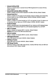
... use dedicated IRQs that allows the storage driver to install a 3rd party add-in network card instead of the integrated SATA controllers. Set this item to Disabled. Enable Native IDE mode if you wish to enable advanced Serial ATA features such as Native Command Queuing and hot plug. GA-EP45T-UD3LR Motherboard - 50 - 2-6 Integrated Peripherals CMOS Setup Utility-Copyright (C) 1984-2008 Award Software SATA RAID/AHCI Mode SATA Port0-3 Native Mode Azalia Codec Onboard H/W LAN Green LAN SMART LAN Onboard LAN Boot ROM Onboard IDE Controller Onboard Serial Port...
... use dedicated IRQs that allows the storage driver to install a 3rd party add-in network card instead of the integrated SATA controllers. Set this item to Disabled. Enable Native IDE mode if you wish to enable advanced Serial ATA features such as Native Command Queuing and hot plug. GA-EP45T-UD3LR Motherboard - 50 - 2-6 Integrated Peripherals CMOS Setup Utility-Copyright (C) 1984-2008 Award Software SATA RAID/AHCI Mode SATA Port0-3 Native Mode Azalia Codec Onboard H/W LAN Green LAN SMART LAN Onboard LAN Boot ROM Onboard IDE Controller Onboard Serial Port...
Manual
Page 52
USB 2.0 Controller Enables or disables the integrated USB 2.0 controller. (Default: Enabled) USB Keyboard Function Allows USB keyboard to be used in MS-DOS. (Default: Disabled) USB Mouse Function Allows USB mouse to detect USB storage devices, including USB flash drives and USB hard drives during the POST. (Default: Enabled) GA-EP45T-UD3LR Motherboard - 52 - Parallel Port Mode Selects an operating mode for the onboard parallel (LPT) port. Options are : 378/IRQ7 (default), 278/IRQ5, 3BC/IRQ7, Disabled. Options are : SPP (Standard Parallel Port)(default), EPP (Enhanced Parallel Port), ...
USB 2.0 Controller Enables or disables the integrated USB 2.0 controller. (Default: Enabled) USB Keyboard Function Allows USB keyboard to be used in MS-DOS. (Default: Disabled) USB Mouse Function Allows USB mouse to detect USB storage devices, including USB flash drives and USB hard drives during the POST. (Default: Enabled) GA-EP45T-UD3LR Motherboard - 52 - Parallel Port Mode Selects an operating mode for the onboard parallel (LPT) port. Options are : 378/IRQ7 (default), 278/IRQ5, 3BC/IRQ7, Disabled. Options are : SPP (Standard Parallel Port)(default), EPP (Enhanced Parallel Port), ...

Manual
Page 71
... Q-Flash, use the key during the POST to access Q-Flash. 2. Step 3: When the update process is complete, press any keEyStCo:Rcoensettinue F10:Power Off - 71 - Select the BIOS update file and press . appears, press to update BIOS?" CoUpypdBaItOe SBIcOomS pfrloetmedD-rPivaess !! Step 1: 1. B. Q-Flash Utility v2.07 Flash Type/Size MXIC 25L8005 1M EnteFr l:oRppuyn A HDD 0-0 Keep DMI Data Enable Update BIOS from the floppy disk is saved to a hard drive in RAID/AHCI mode or a hard drive attached to an independent IDE/SATA controller, use...
... Q-Flash, use the key during the POST to access Q-Flash. 2. Step 3: When the update process is complete, press any keEyStCo:Rcoensettinue F10:Power Off - 71 - Select the BIOS update file and press . appears, press to update BIOS?" CoUpypdBaItOe SBIcOomS pfrloetmedD-rPivaess !! Step 1: 1. B. Q-Flash Utility v2.07 Flash Type/Size MXIC 25L8005 1M EnteFr l:oRppuyn A HDD 0-0 Keep DMI Data Enable Update BIOS from the floppy disk is saved to a hard drive in RAID/AHCI mode or a hard drive attached to an independent IDE/SATA controller, use...

Manual
Page 74
... memory module(s) (or above) to enable support for these changes to take effect or click Default to restore to click Set for your ATI or NVIDIA graphics card. The Memory tab provides information on the installed CPU and motherboard. GA-EP45T-UD3LR Motherboard - 74 - The EasyTune 6 Interface Tabs Information Tab Function The CPU tab provides information on the installed memory module(s). The Smart tab allows you set temperature/fan speed alarm. Smart Fan Advance Mode allows the CPU fan speed...
... memory module(s) (or above) to enable support for these changes to take effect or click Default to restore to click Set for your ATI or NVIDIA graphics card. The Memory tab provides information on the installed CPU and motherboard. GA-EP45T-UD3LR Motherboard - 74 - The EasyTune 6 Interface Tabs Information Tab Function The CPU tab provides information on the installed memory module(s). The Smart tab allows you set temperature/fan speed alarm. Smart Fan Advance Mode allows the CPU fan speed...

Manual
Page 79
...Windows Vista/XP setup disk. • Motherboard driver disk. 5-1-1 Configuring the Onboard SATA Controller A. Make a floppy disk containing the SATA RAID/AHCI driver. (Note 2) E. B. C . Installing SATA hard drive(s) in your power supply to the hard drive. (Note 1) Skip this step if you do not want to create RAID array on the motherboard. Chapter 5 Appendix 5-1 Configuring SATA Hard Drive(s) To configure SATA hard drive(s), follow the steps below: A. If you do not want to AHCI or RAID mode. - 79 - Appendix Configure a RAID array in BIOS Setup. Install the SATA RAID...
...Windows Vista/XP setup disk. • Motherboard driver disk. 5-1-1 Configuring the Onboard SATA Controller A. Make a floppy disk containing the SATA RAID/AHCI driver. (Note 2) E. B. C . Installing SATA hard drive(s) in your power supply to the hard drive. (Note 1) Skip this step if you do not want to create RAID array on the motherboard. Chapter 5 Appendix 5-1 Configuring SATA Hard Drive(s) To configure SATA hard drive(s), follow the steps below: A. If you do not want to AHCI or RAID mode. - 79 - Appendix Configure a RAID array in BIOS Setup. Install the SATA RAID...

Manual
Page 80
...1)(Disabled by default). To create RAID, set this section may differ from the exact settings for your computer and press to enter BIOS Setup during the POST (Power-On Self-Test). B. If you have and the BIOS version. The BIOS Setup menus described in system BIOS Setup . CMOS Setup Utility-Copyright (C) 1984-2008 Award Software SATA RAID/AHCI Mode SATA Port0-3 Native Mode Azalia Codec Onboard H/W LAN Green LAN SMART LAN Onboard LAN Boot ROM Onboard IDE Controller Onboard Serial Port 1 Onboard Parallel Port Parallel Port Mode USB 1.0 Controller USB 2.0 Controller USB Keyboard...
...1)(Disabled by default). To create RAID, set this section may differ from the exact settings for your computer and press to enter BIOS Setup during the POST (Power-On Self-Test). B. If you have and the BIOS version. The BIOS Setup menus described in system BIOS Setup . CMOS Setup Utility-Copyright (C) 1984-2008 Award Software SATA RAID/AHCI Mode SATA Port0-3 Native Mode Azalia Codec Onboard H/W LAN Green LAN SMART LAN Onboard LAN Boot ROM Onboard IDE Controller Onboard Serial Port 1 Onboard Parallel Port Parallel Port Mode USB 1.0 Controller USB 2.0 Controller USB Keyboard...
Manual
Page 86
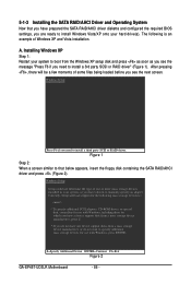
... the SATA RAID/AHCI driver diskette and configured the required BIOS settings, you have a device support disk from the Windows XP setup disk and press as soon as you see the message "Press F6 if you see the next screen. S=Specify Additional Device ENTER=Continue F3=Exit Figure 2 GA-EP45T-UD3LR Motherboard - 86 - Installing Windows XP Step 1: Restart your hard drive(s). 5-1-3 Installing the SATA RAID/AHCI Driver and Operating System Now that below appears, insert the floppy disk containing the SATA RAID/AHCI driver and...
... the SATA RAID/AHCI driver diskette and configured the required BIOS settings, you have a device support disk from the Windows XP setup disk and press as soon as you see the message "Press F6 if you see the next screen. S=Specify Additional Device ENTER=Continue F3=Exit Figure 2 GA-EP45T-UD3LR Motherboard - 86 - Installing Windows XP Step 1: Restart your hard drive(s). 5-1-3 Installing the SATA RAID/AHCI Driver and Operating System Now that below appears, insert the floppy disk containing the SATA RAID/AHCI driver and...
Manual
Page 98
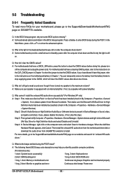
...Award BIOS beep code descriptions may help you identify possible computer problems. (For reference only.) 1 short: System boots successfully 1 long, 3 short: Keyboard error 2 short: CMOS setting error 1 long, 9 short: BIOS ROM error 1 long, 1 short: Memory or motherboard error Continuous long beeps: Graphics card not inserted properly 1 long, 2 short: Monitor or graphics card error Continuous short beeps: Power error GA-EP45T-UD3LR Motherboard - 98 - Press to enter BIOS Setup during the POST mean? In the Main Menu, press + to install. Then make sure Service Pack 1 or Service...
...Award BIOS beep code descriptions may help you identify possible computer problems. (For reference only.) 1 short: System boots successfully 1 long, 3 short: Keyboard error 2 short: CMOS setting error 1 long, 9 short: BIOS ROM error 1 long, 1 short: Memory or motherboard error Continuous long beeps: Graphics card not inserted properly 1 long, 2 short: Monitor or graphics card error Continuous short beeps: Power error GA-EP45T-UD3LR Motherboard - 98 - Press to enter BIOS Setup during the POST mean? In the Main Menu, press + to install. Then make sure Service Pack 1 or Service...


