Manual
Page 1
GA-EP45T-UD3LR LGA775 socket motherboard for Intel® Core TM processor family/ Intel® Pentium® processor family/Intel® Celeron® processor family User's Manual Rev. 1101 12ME-EP45TU3LR-1101R
GA-EP45T-UD3LR LGA775 socket motherboard for Intel® Core TM processor family/ Intel® Pentium® processor family/Intel® Celeron® processor family User's Manual Rev. 1101 12ME-EP45TU3LR-1101R
Manual
Page 2
Motherboard GA-EP45T-UD3LR Oct. 24, 2008 Motherboard GA-EP45T-UD3LR Oct. 24, 2008
Motherboard GA-EP45T-UD3LR Oct. 24, 2008 Motherboard GA-EP45T-UD3LR Oct. 24, 2008
Manual
Page 4
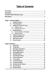
Table of Contents Box Contents ...6 OptionalItems...6 GA-EP45T-UD3LR Motherboard Layout 7 Block Diagram...8 Chapter 1 Hardware Installation 9 1-1 Installation Precautions 9 1-2 Product Specifications 10 1-3 Installing the CPU and CPU Cooler 13 1-3-1 Installing the CPU 13 1-3-2 Installing the ...
Table of Contents Box Contents ...6 OptionalItems...6 GA-EP45T-UD3LR Motherboard Layout 7 Block Diagram...8 Chapter 1 Hardware Installation 9 1-1 Installation Precautions 9 1-2 Product Specifications 10 1-3 Installing the CPU and CPU Cooler 13 1-3-1 Installing the CPU 13 1-3-2 Installing the ...
Manual
Page 6
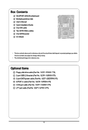
.... 12CR1-1SPDIN-0*R) COM port cable (Part No. 12CF1-1CM001-3*R) LPT port cable (Part No. 12CF1-1LP001-0*R) - 6 - The box contents are for reference only. Box Contents GA-EP45T-UD3LR motherboard Motherboard driver disk User's Manual Quick Installation Guide One IDE cable Two SATA 3Gb/s cables One SATA bracket I/O Shield • The box contents above...
.... 12CR1-1SPDIN-0*R) COM port cable (Part No. 12CF1-1CM001-3*R) LPT port cable (Part No. 12CF1-1LP001-0*R) - 6 - The box contents are for reference only. Box Contents GA-EP45T-UD3LR motherboard Motherboard driver disk User's Manual Quick Installation Guide One IDE cable Two SATA 3Gb/s cables One SATA bracket I/O Shield • The box contents above...

Manual
Page 7
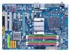
GA-EP45T-UD3LR Motherboard Layout KB_MS R_SPDIF R_USB_1 R_USB_2 R_USB_3 USB_LAN ATX_12V PHASE LED CPU_FAN PWR_FAN ATX LGA775 DDR3_1 GA-EP45T-UD3LR DDR3_2 DDR3_3 DDR3_4 FDD SYS_FAN2 F_AUDIO SYS_FAN1 AUDIO Intel® P45 RTL8111C PCIEX1_1 PCIEX1_2 PCIEX16 CODEC SPDIF_O SPDIF_I PCIEX1_3 PCIEX1_4 B_BIOS M_BIOS BAT PCI1 CLR_CMOS IT8718 PCI2 CD_IN CI Intel® ICH10R SATA2_3 SATA2_0 SATA2_4 SATA2_ 1 JMicron 368 IDE SATA2_5 SATA2_2 F_USB1 F_PANEL PWR_LED COMA LPT F_USB2 - 7 -
GA-EP45T-UD3LR Motherboard Layout KB_MS R_SPDIF R_USB_1 R_USB_2 R_USB_3 USB_LAN ATX_12V PHASE LED CPU_FAN PWR_FAN ATX LGA775 DDR3_1 GA-EP45T-UD3LR DDR3_2 DDR3_3 DDR3_4 FDD SYS_FAN2 F_AUDIO SYS_FAN1 AUDIO Intel® P45 RTL8111C PCIEX1_1 PCIEX1_2 PCIEX16 CODEC SPDIF_O SPDIF_I PCIEX1_3 PCIEX1_4 B_BIOS M_BIOS BAT PCI1 CLR_CMOS IT8718 PCI2 CD_IN CI Intel® ICH10R SATA2_3 SATA2_0 SATA2_4 SATA2_ 1 JMicron 368 IDE SATA2_5 SATA2_2 F_USB1 F_PANEL PWR_LED COMA LPT F_USB2 - 7 -
Manual
Page 10
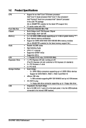
...memory (Note 1) Dual channel memory architecture Support for DDR3 2200/1600/1333/1066/800 MHz memory modules (Go to GIGABYTE's website for the latest memory support list.) Realtek ALC888 codec High Definition Audio 2/4/5.1/7.1-channel Support for... up to 2 IDE devices iTE IT8718 chip: - 1 x floppy disk drive connector supporting up to the internal USB headers) GA-EP45T-UD3LR Motherboard - 10 - 1-2 Product Specifications CPU Front Side Bus Chipset Memory Audio LAN Expansion Slots Storage Interface USB Support for an ...
...memory (Note 1) Dual channel memory architecture Support for DDR3 2200/1600/1333/1066/800 MHz memory modules (Go to GIGABYTE's website for the latest memory support list.) Realtek ALC888 codec High Definition Audio 2/4/5.1/7.1-channel Support for... up to 2 IDE devices iTE IT8718 chip: - 1 x floppy disk drive connector supporting up to the internal USB headers) GA-EP45T-UD3LR Motherboard - 10 - 1-2 Product Specifications CPU Front Side Bus Chipset Memory Audio LAN Expansion Slots Storage Interface USB Support for an ...
Manual
Page 12
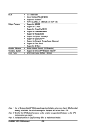
GA-EP45T-UD3LR Motherboard - 12 - BIOS Unique Features Bundled Software Operating System Form Factor 2 x 8 Mbit flash Use of licensed AWARD BIOS Support for DualBIOSTM ...
GA-EP45T-UD3LR Motherboard - 12 - BIOS Unique Features Bundled Software Operating System Form Factor 2 x 8 Mbit flash Use of licensed AWARD BIOS Support for DualBIOSTM ...
Manual
Page 14
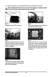
... the protective socket cover when the CPU is properly inserted, replace the load plate and push the CPU socket lever back into its locked position. GA-EP45T-UD3LR Motherboard - 14 - Before installing the CPU, make sure to the CPU.
... the protective socket cover when the CPU is properly inserted, replace the load plate and push the CPU socket lever back into its locked position. GA-EP45T-UD3LR Motherboard - 14 - Before installing the CPU, make sure to the CPU.
Manual
Page 16
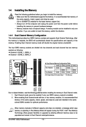
...is recommended that memory of the memory. DS/SS - - Dual Channel mode cannot be populated and remain in Dual Channel mode/performance. GA-EP45T-UD3LR Motherboard - 16 - After the memory is operating in Flex Memory Mode will appear during the POST. The four DDR3 memory sockets are ... Memory Read the following guidelines before installing the memory in Dual Channel mode. 1. A memory module can be used . (Go to GIGABYTE's website for optimum performance. When memory modules of different capacity and chips are divided into two channels and each channel has two memory sockets...
...is recommended that memory of the memory. DS/SS - - Dual Channel mode cannot be populated and remain in Dual Channel mode/performance. GA-EP45T-UD3LR Motherboard - 16 - After the memory is operating in Flex Memory Mode will appear during the POST. The four DDR3 memory sockets are ... Memory Read the following guidelines before installing the memory in Dual Channel mode. 1. A memory module can be used . (Go to GIGABYTE's website for optimum performance. When memory modules of different capacity and chips are divided into two channels and each channel has two memory sockets...
Manual
Page 18
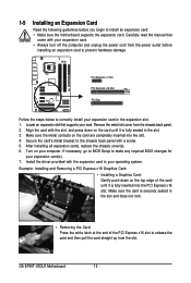
... down on the top edge of the PCI Express x16 slot to release the card and then pull the card straight up from the slot. GA-EP45T-UD3LR Motherboard - 18 - Install the driver provided with your expansion card. • Always turn off the computer and unplug the power cord from the chassis back...
... down on the top edge of the PCI Express x16 slot to release the card and then pull the card straight up from the slot. GA-EP45T-UD3LR Motherboard - 18 - Install the driver provided with your expansion card. • Always turn off the computer and unplug the power cord from the chassis back...
Manual
Page 20
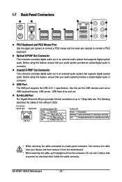
... is occurring Off No data transmission or receiving is occurring • When removing the cable connected to prevent an electrical short inside the cable connector. GA-EP45T-UD3LR Motherboard - 20 - Use this feature, ensure that your audio system provides an optical digital audio in connector. The following describes the states of the LAN...
... is occurring Off No data transmission or receiving is occurring • When removing the cable connected to prevent an electrical short inside the cable connector. GA-EP45T-UD3LR Motherboard - 20 - Use this feature, ensure that your audio system provides an optical digital audio in connector. The following describes the states of the LAN...

Manual
Page 22
GA-EP45T-UD3LR Motherboard - 22 - Unplug the power cord from the power outlet to prevent damage to the devices. • After installing the device and before connecting external ...
GA-EP45T-UD3LR Motherboard - 22 - Unplug the power cord from the power outlet to prevent damage to the devices. • After installing the device and before connecting external ...
Manual
Page 24
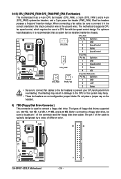
...). Do not place a jumper cap on the headers. 6) FDD (Floppy Disk Drive Connector) This connector is typically designated by a stripe of different color. 34 33 GA-EP45T-UD3LR Motherboard 2 1 - 24 - The pin 1 of floppy disk drives supported are not configuration jumper blocks. For optimum heat dissipation, it in damage to the CPU or...
...). Do not place a jumper cap on the headers. 6) FDD (Floppy Disk Drive Connector) This connector is typically designated by a stripe of different color. 34 33 GA-EP45T-UD3LR Motherboard 2 1 - 24 - The pin 1 of floppy disk drives supported are not configuration jumper blocks. For optimum heat dissipation, it in damage to the CPU or...

Manual
Page 26
... the chassis to Chapter 5, "Configuring 2/4/5.1/7.1-Channel Audio." • Some chassis provide a front panel audio module that has different wire assignments, please contact the chassis manufacturer. GA-EP45T-UD3LR Motherboard - 26 - Definition 1 1 2 2 MIC2_L GND 1 MIC 2 GND 3 MIC2_R 3 MIC Power 9 10 4 -ACZ_DET 4 NC 5 LINE2_R 5 Line Out (R) 6 GND 6 NC 7 FAUDIO_JD 7 NC 8 No Pin 8 No Pin 9 LINE2_L...
... the chassis to Chapter 5, "Configuring 2/4/5.1/7.1-Channel Audio." • Some chassis provide a front panel audio module that has different wire assignments, please contact the chassis manufacturer. GA-EP45T-UD3LR Motherboard - 26 - Definition 1 1 2 2 MIC2_L GND 1 MIC 2 GND 3 MIC2_R 3 MIC Power 9 10 4 -ACZ_DET 4 NC 5 LINE2_R 5 Line Out (R) 6 GND 6 NC 7 FAUDIO_JD 7 NC 8 No Pin 8 No Pin 9 LINE2_L...

Manual
Page 28
Definition 1 Power 2 SPDIFI 3 GND GA-EP45T-UD3LR Motherboard - 28 - Pin No. For purchasing the optional S/PDIF in cable, please contact the local dealer. 1 Pin No. Definition 1 CD-L 2 GND 3 GND 4 CD-R 1 13) SPDIF_I (S/PDIF In Header) This header supports digital S/PDIF in and can connect to the header. 12) CD_IN (CD In Connector) You may connect the audio cable that came with your optical drive to an audio device that supports digital audio out via an optional S/PDIF in cable.
Definition 1 Power 2 SPDIFI 3 GND GA-EP45T-UD3LR Motherboard - 28 - Pin No. For purchasing the optional S/PDIF in cable, please contact the local dealer. 1 Pin No. Definition 1 CD-L 2 GND 3 GND 4 CD-R 1 13) SPDIF_I (S/PDIF In Header) This header supports digital S/PDIF in and can connect to the header. 12) CD_IN (CD In Connector) You may connect the audio cable that came with your optical drive to an audio device that supports digital audio out via an optional S/PDIF in cable.

Manual
Page 30
... optional COM port cable, please contact the local dealer. 9 1 10 2 Pin No. 1 2 3 4 5 6 7 8 9 10 Definition NDCD NSIN NSOUT NDTR GND NDSR NRTS NCTS NRI No Pin GA-EP45T-UD3LR Motherboard - 30 - 16) LPT (Parallel Port Header) The LPT header can provide one parallel port via an optional COM port cable.
... optional COM port cable, please contact the local dealer. 9 1 10 2 Pin No. 1 2 3 4 5 6 7 8 9 10 Definition NDCD NSIN NSOUT NDTR GND NDSR NRTS NCTS NRI No Pin GA-EP45T-UD3LR Motherboard - 30 - 16) LPT (Parallel Port Header) The LPT header can provide one parallel port via an optional COM port cable.
Manual
Page 32
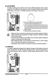
... the orientation of the positive side (+) and the negative side (-) of the battery (the positive side should face up). • Used batteries must be lost. GA-EP45T-UD3LR Motherboard - 32 - 20) BAT (BATTERY) The battery provides power to keep the values (such as BIOS configurations, date, and time information) in the CMOS when...
... the orientation of the positive side (+) and the negative side (-) of the battery (the positive side should face up). • Used batteries must be lost. GA-EP45T-UD3LR Motherboard - 32 - 20) BAT (BATTERY) The battery provides power to keep the values (such as BIOS configurations, date, and time information) in the CMOS when...
Manual
Page 34
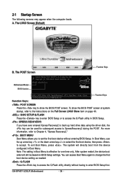
... to enter BIOS Setup or to access the Q-Flash utility in Boot Menu is effective for subsequent access to enter BIOS Setup first. GA-EP45T-UD3LR Motherboard - 34 - The POST Screen Award Modular BIOS v6.00PG, An Energy Star Ally Copyright (C) 1984-2008, Award Software, Inc. ...Motherboard Model BIOS Version EP45T-UD3LR E12c . . . . : BIOS Setup : XpressRecovery2 : Boot Menu : Qflash 10/09/2008-P45-ICH10-7A69PG09C-00 Function Keys Function Keys: : POST SCREEN...
... to enter BIOS Setup or to access the Q-Flash utility in Boot Menu is effective for subsequent access to enter BIOS Setup first. GA-EP45T-UD3LR Motherboard - 34 - The POST Screen Award Modular BIOS v6.00PG, An Energy Star Ally Copyright (C) 1984-2008, Award Software, Inc. ...Motherboard Model BIOS Version EP45T-UD3LR E12c . . . . : BIOS Setup : XpressRecovery2 : Boot Menu : Qflash 10/09/2008-P45-ICH10-7A69PG09C-00 Function Keys Function Keys: : POST SCREEN...
Manual
Page 36
... a profile created before, without the hassles of reconfiguring the BIOS settings. First enter the profile name (to erase the default profile name, use this task.) GA-EP45T-UD3LR Motherboard - 36 - It allows you can create up to the system and BIOS Setup. The Functions of the and keys (For the Main Menu...
... a profile created before, without the hassles of reconfiguring the BIOS settings. First enter the profile name (to erase the default profile name, use this task.) GA-EP45T-UD3LR Motherboard - 36 - It allows you can create up to the system and BIOS Setup. The Functions of the and keys (For the Main Menu...
Manual
Page 38
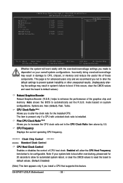
... you not to alter the default settings to prevent system instability or other unexpected results. (Inadequately altering the settings may result in damage to boot. GA-EP45T-UD3LR Motherboard - 38 - The item is installed. Incorrectly doing overclock/overvoltage may result in the CPU Clock Ratio item above by 0.5. Enabled will work stably with...
... you not to alter the default settings to prevent system instability or other unexpected results. (Inadequately altering the settings may result in damage to boot. GA-EP45T-UD3LR Motherboard - 38 - The item is installed. Incorrectly doing overclock/overvoltage may result in the CPU Clock Ratio item above by 0.5. Enabled will work stably with...


