Manual
Page 1
GA-EP45C-UD3R/ GA-EP45C-UD3 LGA775 socket motherboard for Intel® CoreTM processor family/ Intel® Pentium® processor family/Intel® Celeron® processor family User's Manual Rev. 1001 12ME-EP45CUD3R-1001R
GA-EP45C-UD3R/ GA-EP45C-UD3 LGA775 socket motherboard for Intel® CoreTM processor family/ Intel® Pentium® processor family/Intel® Celeron® processor family User's Manual Rev. 1001 12ME-EP45CUD3R-1001R

Manual
Page 2
Motherboard GA-EP45C-UD3R/GA-EP45C-UD3 Oct. 22, 2008 Motherboard GA-EP45C-UD3R/ GA-EP45C-UD3 Oct. 22, 2008
Motherboard GA-EP45C-UD3R/GA-EP45C-UD3 Oct. 22, 2008 Motherboard GA-EP45C-UD3R/ GA-EP45C-UD3 Oct. 22, 2008
Manual
Page 3
...any form or by GIGABYTE without GIGABYTE's prior written permission. Copyright © 2008 GIGA-BYTE TECHNOLOGY CO., LTD. All rights reserved. For example, "REV: 1.0" means the revision of the motherboard is the property of GIGABYTE. Example: Check your motherboard looks like this ...manual may be made by any means without prior notice. Changes to use of this product, GIGABYTE provides the following types of documentations: „...
...any form or by GIGABYTE without GIGABYTE's prior written permission. Copyright © 2008 GIGA-BYTE TECHNOLOGY CO., LTD. All rights reserved. For example, "REV: 1.0" means the revision of the motherboard is the property of GIGABYTE. Example: Check your motherboard looks like this ...manual may be made by any means without prior notice. Changes to use of this product, GIGABYTE provides the following types of documentations: „...
Manual
Page 4
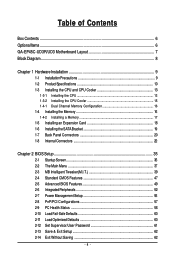
Table of Contents Box Contents ...6 OptionalItems...6 GA-EP45C-UD3R/UD3 Motherboard Layout 7 Block Diagram...8 Chapter 1 Hardware Installation 9 1-1 Installation Precautions 9 1-2 Product Specifications 10 1-3 Installing the CPU and CPU Cooler 13 1-3-1 Installing the CPU 13 1-3-2 Installing the CPU ...
Table of Contents Box Contents ...6 OptionalItems...6 GA-EP45C-UD3R/UD3 Motherboard Layout 7 Block Diagram...8 Chapter 1 Hardware Installation 9 1-1 Installation Precautions 9 1-2 Product Specifications 10 1-3 Installing the CPU and CPU Cooler 13 1-3-1 Installing the CPU 13 1-3-2 Installing the CPU ...
Manual
Page 6
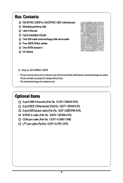
...01R) COM port cable (Part No. 12CF1-1CM001-32R) LPT port cable (Part No. 12CF1-1LP001-01R) - 6 - Box Contents GA-EP45C-UD3R or GA-EP45C-UD3 motherboard Motherboard driver disk User's Manual Quick Installation Guide One IDE cable and one floppy disk drive cable Four SATA 3Gb/s cables One SATA bracket I/O ...Shield Only for GA-EP45C-UD3R. • The box contents above are subject to change without notice. • The motherboard image is for reference only and the actual items shall depend on product package you obtain....
...01R) COM port cable (Part No. 12CF1-1CM001-32R) LPT port cable (Part No. 12CF1-1LP001-01R) - 6 - Box Contents GA-EP45C-UD3R or GA-EP45C-UD3 motherboard Motherboard driver disk User's Manual Quick Installation Guide One IDE cable and one floppy disk drive cable Four SATA 3Gb/s cables One SATA bracket I/O ...Shield Only for GA-EP45C-UD3R. • The box contents above are subject to change without notice. • The motherboard image is for reference only and the actual items shall depend on product package you obtain....
Manual
Page 7
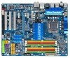
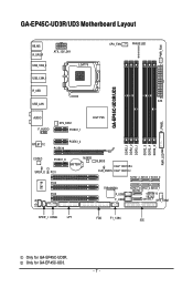
Only for GA-EP45C-UD3R. GA-EP45C-UD3R/UD3 Motherboard Layout PWR_FAN KB_MS R_SPDIF ATX_12V_2X4 USB_1394_2 LGA775 USB_1394_1 R_USB USB_LAN CPU_FAN PHASE LED ATX GA-EP45C-UD3R/UD3 F_PANEL AUDIO F_AUDIO SYS_FAN1 ...PCIEX1_1 Intel® P45 DDR2_1 DDR2_2 DDR3_1 DDR2_3 DDR2_4 DDR3_2 PWR_LED RTL8111C PCIEX16 PCIEX1_2 CODEC SPDIF_O IT8718 CI PCIEX1_3 M_BIOS BATTERY PCI1 PCI2 PCI3 B_BIOS Intel® ICH10R CLR_CMOS Intel® ICH10 SATA2_4 SATA2_2 SATA2_0 TSB43AB23 F_USB1 F_USB2 SATA2_5 SATA2_3 SATA2_1 GSATA2_0 GIGABYTE...
Only for GA-EP45C-UD3R. GA-EP45C-UD3R/UD3 Motherboard Layout PWR_FAN KB_MS R_SPDIF ATX_12V_2X4 USB_1394_2 LGA775 USB_1394_1 R_USB USB_LAN CPU_FAN PHASE LED ATX GA-EP45C-UD3R/UD3 F_PANEL AUDIO F_AUDIO SYS_FAN1 ...PCIEX1_1 Intel® P45 DDR2_1 DDR2_2 DDR3_1 DDR2_3 DDR2_4 DDR3_2 PWR_LED RTL8111C PCIEX16 PCIEX1_2 CODEC SPDIF_O IT8718 CI PCIEX1_3 M_BIOS BATTERY PCI1 PCI2 PCI3 B_BIOS Intel® ICH10R CLR_CMOS Intel® ICH10 SATA2_4 SATA2_2 SATA2_0 TSB43AB23 F_USB1 F_USB2 SATA2_5 SATA2_3 SATA2_1 GSATA2_0 GIGABYTE...
Manual
Page 9
... damaged as a result of the product, please consult a certified computer technician. - 9 - Chapter 1 Hardware Installation 1-1 Installation Precautions The motherboard contains numerous delicate electronic circuits and components which can lead to damage to system components as well as physical harm to the user. •...turned off. • Before turning on the power, make sure they are connected tightly and securely. • When handling the motherboard, avoid touching any metal leads or connectors. • It is best to wear an electrostatic discharge (ESD) wrist strap when handling...
... damaged as a result of the product, please consult a certified computer technician. - 9 - Chapter 1 Hardware Installation 1-1 Installation Precautions The motherboard contains numerous delicate electronic circuits and components which can lead to damage to system components as well as physical harm to the user. •...turned off. • Before turning on the power, make sure they are connected tightly and securely. • When handling the motherboard, avoid touching any metal leads or connectors. • It is best to wear an electrostatic discharge (ESD) wrist strap when handling...
Manual
Page 10
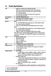
... disk drive Only for GA-EP45C-UD3R. Support for SATA RAID 0, RAID 1, and JBOD iTE IT8718 chip: - 1 x floppy disk drive connector supporting up to 6 SATA 3Gb/s devices - Only for GA-EP45C-UD3. Support for SATA RAID 0, RAID 1, RAID 5 and RAID 10 GIGABYTE SATA2 chip: - 1...2000/1600/13331066/800 MHz memory modules DDR2: 4 x 1.8V DDR2 DIMM sockets supporting up to 2 SATA 3Gb/s devices - GA-EP45C-UD3R/UD3 Motherboard - 10 - 1-2 Product Specifications CPU Front Side Bus Chipset Memory Audio LAN Expansion Slots Storage Interface Support for an Intel®...
... disk drive Only for GA-EP45C-UD3R. Support for SATA RAID 0, RAID 1, and JBOD iTE IT8718 chip: - 1 x floppy disk drive connector supporting up to 6 SATA 3Gb/s devices - Only for GA-EP45C-UD3. Support for SATA RAID 0, RAID 1, RAID 5 and RAID 10 GIGABYTE SATA2 chip: - 1...2000/1600/13331066/800 MHz memory modules DDR2: 4 x 1.8V DDR2 DIMM sockets supporting up to 2 SATA 3Gb/s devices - GA-EP45C-UD3R/UD3 Motherboard - 10 - 1-2 Product Specifications CPU Front Side Bus Chipset Memory Audio LAN Expansion Slots Storage Interface Support for an Intel®...
Manual
Page 12
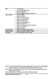
GA-EP45C-UD3R/UD3 Motherboard - 12 - BIOS Unique Features Bundled Software Operating System Form Factor Š 2 x 8 Mbit flash Š Use of licensed AWARD BIOS Š Support for DualBIOSTM Š PnP 1.... CPU/System fan speed control function is supported will depend on the CPU/ System cooler you install. (Note 3) Available functions in EasyTune may differ by motherboard model.
GA-EP45C-UD3R/UD3 Motherboard - 12 - BIOS Unique Features Bundled Software Operating System Form Factor Š 2 x 8 Mbit flash Š Use of licensed AWARD BIOS Š Support for DualBIOSTM Š PnP 1.... CPU/System fan speed control function is supported will depend on the CPU/ System cooler you install. (Note 3) Available functions in EasyTune may differ by motherboard model.
Manual
Page 13
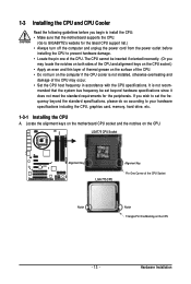
... prevent hardware damage. • Locate the pin one of the CPU. Locate the alignment keys on the motherboard CPU socket and the notches on the CPU - 13 - mended that the motherboard supports the CPU. (Go to GIGABYTE's website for the peripherals. 1-3 Installing the CPU and CPU Cooler Read the following guidelines before installing...
... prevent hardware damage. • Locate the pin one of the CPU. Locate the alignment keys on the motherboard CPU socket and the notches on the CPU - 13 - mended that the motherboard supports the CPU. (Go to GIGABYTE's website for the peripherals. 1-3 Installing the CPU and CPU Cooler Read the following guidelines before installing...
Manual
Page 14
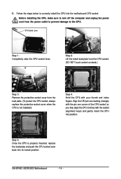
... one marking (triangle) with the pin one corner of the CPU socket (or you may align the CPU notches with your thumb and index fingers. GA-EP45C-UD3R/UD3 Motherboard - 14 - Follow the steps below to the CPU. Step 5: Once the CPU is not installed.) Step 4: Hold the CPU with the socket alignment keys...
... one marking (triangle) with the pin one corner of the CPU socket (or you may align the CPU notches with your thumb and index fingers. GA-EP45C-UD3R/UD3 Motherboard - 14 - Follow the steps below to the CPU. Step 5: Once the CPU is not installed.) Step 4: Hold the CPU with the socket alignment keys...
Manual
Page 15
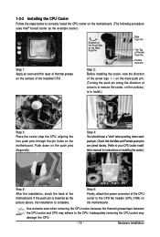
...steps below to your CPU cooler installation manual for instructions on installing the cooler.) Step 5: After the installation, check the back of the motherboard. Use extreme care when removing the CPU cooler because the thermal grease/tape between the CPU cooler and CPU may damage the CPU. ...header (CPU_FAN) on the push pins diagonally. Step 6: Finally, attach the power connector of arrow is to remove the cooler, on the motherboard. Hardware Installation Inadequately removing the CPU cooler may adhere to install.) Step 3: Place the cooler atop the CPU, aligning the four push pins...
...steps below to your CPU cooler installation manual for instructions on installing the cooler.) Step 5: After the installation, check the back of the motherboard. Use extreme care when removing the CPU cooler because the thermal grease/tape between the CPU cooler and CPU may damage the CPU. ...header (CPU_FAN) on the push pins diagonally. Step 6: Finally, attach the power connector of arrow is to remove the cooler, on the motherboard. Hardware Installation Inadequately removing the CPU cooler may adhere to install.) Step 3: Place the cooler atop the CPU, aligning the four push pins...

Manual
Page 16
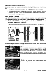
..., DDR3_2) are unable to GIGABYTE's website for optimum performance. Intel® Flex Memory Technology offers greater flexibility to upgrade by allowing different memory sizes to be used . (Go to insert the memory, switch the direction. • Mixed mode, populating DDR2 and DDR3 memory modules simultaneously is installed. 2. GA-EP45C-UD3R/UD3 Motherboard - 16 - After the...
..., DDR3_2) are unable to GIGABYTE's website for optimum performance. Intel® Flex Memory Technology offers greater flexibility to upgrade by allowing different memory sizes to be used . (Go to insert the memory, switch the direction. • Mixed mode, populating DDR2 and DDR3 memory modules simultaneously is installed. 2. GA-EP45C-UD3R/UD3 Motherboard - 16 - After the...
Manual
Page 17
... the memory, push down on the memory and insert it can only fit in the DDR3_1 and DDR3_2 sockets. Place the memory module on this motherboard. Follow the steps below to the memory module. As indicated in the picture on the left, place your memory modules in Dual Channel mode. 1. When...
... the memory, push down on the memory and insert it can only fit in the DDR3_1 and DDR3_2 sockets. Place the memory module on this motherboard. Follow the steps below to the memory module. As indicated in the picture on the left, place your memory modules in Dual Channel mode. 1. When...
Manual
Page 18
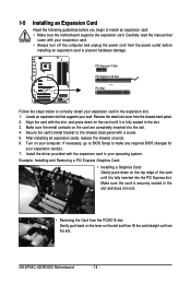
... turn off the computer and unplug the power cord from the power outlet before you begin to install an expansion card: • Make sure the motherboard supports the expansion card. Turn on the card are completely inserted into the PCI Express slot. If necessary, go to BIOS Setup to prevent hardware... before installing an expansion card to make any required BIOS changes for your operating system. Make sure the card is fully inserted into the slot. 4. GA-EP45C-UD3R/UD3 Motherboard - 18 -
... turn off the computer and unplug the power cord from the power outlet before you begin to install an expansion card: • Make sure the motherboard supports the expansion card. Turn on the card are completely inserted into the PCI Express slot. If necessary, go to BIOS Setup to prevent hardware... before installing an expansion card to make any required BIOS changes for your operating system. Make sure the card is fully inserted into the slot. 4. GA-EP45C-UD3R/UD3 Motherboard - 18 -
Manual
Page 19
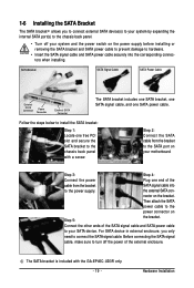
... SATA power cable to the power connector on the bracket. Connect the other ends of the SATA signal cable and SATA power cable to your motherboard. Step 2: Connect the SATA cable from the bracket SATA signal cable into the corresponding connectors when installing. the external SATA con- nector on Step 5: the... steps below to install the SATA bracket: Step 1: Locate one free PCI slot and secure the SATA bracket to the chassis back panel with the GA-EP45C-UD3R only. - 19 -
... SATA power cable to the power connector on the bracket. Connect the other ends of the SATA signal cable and SATA power cable to your motherboard. Step 2: Connect the SATA cable from the bracket SATA signal cable into the corresponding connectors when installing. the external SATA con- nector on Step 5: the... steps below to install the SATA bracket: Step 1: Locate one free PCI slot and secure the SATA bracket to the chassis back panel with the GA-EP45C-UD3R only. - 19 -
Manual
Page 20
... the cable connected to an external audio system that your device and then remove it from your audio system provides a coaxial digital audio in connector. GA-EP45C-UD3R/UD3 Motherboard - 20 - Optical S/PDIF Out Connector This connector provides digital audio out to a back panel connector, first remove the cable from the...
... the cable connected to an external audio system that your device and then remove it from your audio system provides a coaxial digital audio in connector. GA-EP45C-UD3R/UD3 Motherboard - 20 - Optical S/PDIF Out Connector This connector provides digital audio out to a back panel connector, first remove the cable from the...

Manual
Page 22
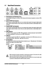
... device and before connecting external devices: • First make sure the device cable has been securely attached to turn off the devices and your computer. GA-EP45C-UD3R/UD3 Motherboard - 22 - 1-8 Internal Connectors 1 3 22 5 2 4 11 12 10 23 21 15 20 8 9 4 13 14 19 18 6 17 16 7 1) ATX_12V_2X4 2) ATX 3) CPU_FAN 4) SYS_FAN1/SYS_FAN2 5) PWR_FAN 6) FDD..., make sure your devices are compliant with the connectors you wish to connect. • Before installing the devices, be sure to the connector on the motherboard.
... device and before connecting external devices: • First make sure the device cable has been securely attached to turn off the devices and your computer. GA-EP45C-UD3R/UD3 Motherboard - 22 - 1-8 Internal Connectors 1 3 22 5 2 4 11 12 10 23 21 15 20 8 9 4 13 14 19 18 6 17 16 7 1) ATX_12V_2X4 2) ATX 3) CPU_FAN 4) SYS_FAN1/SYS_FAN2 5) PWR_FAN 6) FDD..., make sure your devices are compliant with the connectors you wish to connect. • Before installing the devices, be sure to the connector on the motherboard.
Manual
Page 23
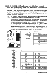
... 2x10 power connectors. The power connector possesses a foolproof design. If a power supply is turned off and all the components on the motherboard. Connect the power supply cable to the CPU. Do not insert the power supply cables into pins under the protective covers when using...providing a 2x4 12V and a 2x12 power connector, remove the protective covers from the 12V power connector and the main power connector on the motherboard. Hardware Installation The 12V power connector mainly supplies power to the power connector in the correct orientation. Definition 1 GND (Only for 2x4 pin...
... 2x10 power connectors. The power connector possesses a foolproof design. If a power supply is turned off and all the components on the motherboard. Connect the power supply cable to the CPU. Do not insert the power supply cables into pins under the protective covers when using...providing a 2x4 12V and a 2x12 power connector, remove the protective covers from the 12V power connector and the main power connector on the motherboard. Hardware Installation The 12V power connector mainly supplies power to the power connector in the correct orientation. Definition 1 GND (Only for 2x4 pin...
Manual
Page 24
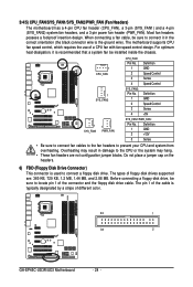
For optimum heat dissipation, it in damage to locate pin 1 of different color. 33 1 34 2 GA-EP45C-UD3R/UD3 Motherboard - 24 - Definition 1 GND 2 +12V 3 Sense • Be sure to connect fan cables to the fan headers to connect ...Control Sense Speed Control 1 SYS_FAN2 SYS_FAN2: Pin No. 1 2 3 4 Definition GND Speed Control Sense +5V 1 SYS_FAN1 1 PWR_FAN SYS_FAN1/PWR_FAN: Pin No. The motherboard supports CPU fan speed control, which requires the use of floppy disk drives supported are not configuration jumper blocks. Most fan headers possess a foolproof insertion...
For optimum heat dissipation, it in damage to locate pin 1 of different color. 33 1 34 2 GA-EP45C-UD3R/UD3 Motherboard - 24 - Definition 1 GND 2 +12V 3 Sense • Be sure to connect fan cables to the fan headers to connect ...Control Sense Speed Control 1 SYS_FAN2 SYS_FAN2: Pin No. 1 2 3 4 Definition GND Speed Control Sense +5V 1 SYS_FAN1 1 PWR_FAN SYS_FAN1/PWR_FAN: Pin No. The motherboard supports CPU fan speed control, which requires the use of floppy disk drives supported are not configuration jumper blocks. Most fan headers possess a foolproof insertion...


