
Manual
Page 3
... in this manual is protected by copyright laws and is 1.0. Documentation Classifications In order to assist in any form or by GIGABYTE without GIGABYTE's prior written permission. For example, "REV: 1.0" means the revision of the motherboard is the property of this manual may...features, read or download the information on/from the Support&Downloads\Motherboard\Technology Guide page on your motherboard revision before updating motherboard BIOS, drivers, or when looking for technical information. Example: Copyright © 2009 GIGA-BYTE TECHNOLOGY CO., LTD. Disclaimer Information...
... in this manual is protected by copyright laws and is 1.0. Documentation Classifications In order to assist in any form or by GIGABYTE without GIGABYTE's prior written permission. For example, "REV: 1.0" means the revision of the motherboard is the property of this manual may...features, read or download the information on/from the Support&Downloads\Motherboard\Technology Guide page on your motherboard revision before updating motherboard BIOS, drivers, or when looking for technical information. Example: Copyright © 2009 GIGA-BYTE TECHNOLOGY CO., LTD. Disclaimer Information...

Manual
Page 4
Table of Contents Box Contents ...6 OptionalItems ...6 GA-EP45-UD3R/UD3 Motherboard Layout 7 Block Diagram ...8 Chapter 1 Hardware Installation 9 1-1 Installation Precautions 9 1-2 Product Specifications 10 1-3 Installing the CPU and CPU Cooler...Installing the SATA Bracket 19 1-7 Back Panel Connectors 20 1-8 Internal Connectors 22 Chapter 2 BIOS Setup 35 2-1 Startup Screen 36 2-2 The Main Menu 37 2-3 MB Intelligent Tweaker(M.I.T 39 2-4 Standard CMOS Features 47 2-5 Advanced BIOS Features 49 2-6 IntegratedPeripherals 52 2-7 Power Management Setup 56 2-8 PnP/PCI Configurations 58 ...
Table of Contents Box Contents ...6 OptionalItems ...6 GA-EP45-UD3R/UD3 Motherboard Layout 7 Block Diagram ...8 Chapter 1 Hardware Installation 9 1-1 Installation Precautions 9 1-2 Product Specifications 10 1-3 Installing the CPU and CPU Cooler...Installing the SATA Bracket 19 1-7 Back Panel Connectors 20 1-8 Internal Connectors 22 Chapter 2 BIOS Setup 35 2-1 Startup Screen 36 2-2 The Main Menu 37 2-3 MB Intelligent Tweaker(M.I.T 39 2-4 Standard CMOS Features 47 2-5 Advanced BIOS Features 49 2-6 IntegratedPeripherals 52 2-7 Power Management Setup 56 2-8 PnP/PCI Configurations 58 ...
Manual
Page 5
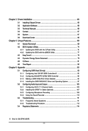
...Utilities 74 4-2-1 Updating the BIOS with the Q-Flash Utility 74 4-2-2 Updating the BIOS with the @BIOS Utility 77 4-3 EasyTune 6 ...78 4-4 Dynamic Energy Saver Advanced 79 4-5 Q-Share ...81 4-6 Time Repair ...82 Chapter 5 Appendix ...83 5-1 Configuring SATA Hard Drive(s 83 5-1-1 Configuring Intel ICH10R SATA Controllers1 83 5-1-2 Configuring GIGABYTE SATA2 SATA Controller 89 ... Recording 108 5-2-4 Using the Sound Recorder 110 5-3 Troubleshooting 111 5-3-1 Frequently Asked Questions 111 5-3-2 Troubleshooting Procedure 112 5-4 Regulatory Statements 114 1 Only for GA-EP45-UD3R. - 5 -
...Utilities 74 4-2-1 Updating the BIOS with the Q-Flash Utility 74 4-2-2 Updating the BIOS with the @BIOS Utility 77 4-3 EasyTune 6 ...78 4-4 Dynamic Energy Saver Advanced 79 4-5 Q-Share ...81 4-6 Time Repair ...82 Chapter 5 Appendix ...83 5-1 Configuring SATA Hard Drive(s 83 5-1-1 Configuring Intel ICH10R SATA Controllers1 83 5-1-2 Configuring GIGABYTE SATA2 SATA Controller 89 ... Recording 108 5-2-4 Using the Sound Recorder 110 5-3 Troubleshooting 111 5-3-1 Frequently Asked Questions 111 5-3-2 Troubleshooting Procedure 112 5-4 Regulatory Statements 114 1 Only for GA-EP45-UD3R. - 5 -
Manual
Page 8
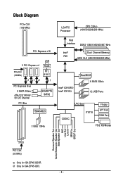
... CLK (100 MHz) x1 x1 x1 LAN RJ45 RTL 8111C x1 PCI Express Bus 2 SATA 3Gb/s ATA-133/100/66/ 33 IDE Channel PCI Bus GIGABYTE SATA2 TSB43AB23 3 IEEE 1394a Host Interface DDR2 1366/1066/800/667 MHz Intel® P45 Dual Channel Memory MCH CLK (400/333/266/200 MHz... Intel® ICH102 Dual BIOS 6 SATA 3Gb/s 12 USB Ports CODEC LPC Bus IT8718 Floppy LPT Port COM Port PS/2 KB/Mouse Surround Speaker Out Center/Subwoofer Speaker Out Side Speaker Out MIC Line-Out Line-In SPDIF In SPDIF Out 3 PCI PCI CLK (33 MHz) 1 Only for GA-EP45-UD3R. 2 Only for GA-EP45-UD3. - 8 -
... CLK (100 MHz) x1 x1 x1 LAN RJ45 RTL 8111C x1 PCI Express Bus 2 SATA 3Gb/s ATA-133/100/66/ 33 IDE Channel PCI Bus GIGABYTE SATA2 TSB43AB23 3 IEEE 1394a Host Interface DDR2 1366/1066/800/667 MHz Intel® P45 Dual Channel Memory MCH CLK (400/333/266/200 MHz... Intel® ICH102 Dual BIOS 6 SATA 3Gb/s 12 USB Ports CODEC LPC Bus IT8718 Floppy LPT Port COM Port PS/2 KB/Mouse Surround Speaker Out Center/Subwoofer Speaker Out Side Speaker Out MIC Line-Out Line-In SPDIF In SPDIF Out 3 PCI PCI CLK (33 MHz) 1 Only for GA-EP45-UD3R. 2 Only for GA-EP45-UD3. - 8 -

Manual
Page 12
... Software Operating System Form Factor Š 2 x 8 Mbit flash Š Use of licensed AWARD BIOS Š Support for DualBIOSTM Š PnP 1.0a, DMI 2.0, SM BIOS 2.4, ACPI 1.0b Š Support for @BIOS Š Support for Q-Flash Š Support for Virtual Dual BIOS Š Support for Download Center Š Support for Xpress Install Š Support for Xpress... fan speed control function is supported will depend on the CPU/ System cooler you install. (Note 3) Available functions in EasyTune may differ by motherboard model. GA-EP45-UD3R/UD3 Motherboard - 12 -
... Software Operating System Form Factor Š 2 x 8 Mbit flash Š Use of licensed AWARD BIOS Š Support for DualBIOSTM Š PnP 1.0a, DMI 2.0, SM BIOS 2.4, ACPI 1.0b Š Support for @BIOS Š Support for Q-Flash Š Support for Virtual Dual BIOS Š Support for Download Center Š Support for Xpress Install Š Support for Xpress... fan speed control function is supported will depend on the CPU/ System cooler you install. (Note 3) Available functions in EasyTune may differ by motherboard model. GA-EP45-UD3R/UD3 Motherboard - 12 -

Manual
Page 16
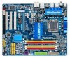
... support list.) • Always turn off the computer and unplug the power cord from the power outlet before installing the memory to GIGABYTE's website for optimum performance. GA-EP45-UD3R/UD3 Motherboard - 16 - After the memory is recommended that the motherboard supports the memory. DS/SS - - - - DS/... allowing different memory sizes to install the memory: • Make sure that memory of the memory. It is installed, the BIOS will automatically detect the specifications and capacity of the same capacity, brand, speed, and chips be installed in Dual Channel mode/performance...
... support list.) • Always turn off the computer and unplug the power cord from the power outlet before installing the memory to GIGABYTE's website for optimum performance. GA-EP45-UD3R/UD3 Motherboard - 16 - After the memory is recommended that the motherboard supports the memory. DS/SS - - - - DS/... allowing different memory sizes to install the memory: • Make sure that memory of the memory. It is installed, the BIOS will automatically detect the specifications and capacity of the same capacity, brand, speed, and chips be installed in Dual Channel mode/performance...

Manual
Page 18
Make sure the metal contacts on the card are completely inserted into the PCI Express slot. GA-EP45-UD3R/UD3 Motherboard - 18 - Carefully read the manual that supports your expansion card(s). 7. Remove the metal slot cover from the slot. After installing all expansion cards, ... x1 Slot PCI Express x16 Slot PCI Slot Follow the steps below to make any required BIOS changes for your card. Align the card with your expansion card in your computer. If necessary, go to BIOS Setup to correctly install your expansion card. • Always turn off the computer and unplug the...
Make sure the metal contacts on the card are completely inserted into the PCI Express slot. GA-EP45-UD3R/UD3 Motherboard - 18 - Carefully read the manual that supports your expansion card(s). 7. Remove the metal slot cover from the slot. After installing all expansion cards, ... x1 Slot PCI Express x16 Slot PCI Slot Follow the steps below to make any required BIOS changes for your card. Align the card with your expansion card in your computer. If necessary, go to BIOS Setup to correctly install your expansion card. • Always turn off the computer and unplug the...

Manual
Page 27
... the chassis front panel. PW+ PWSPEAK+ SPEAK- 2 20 1 19 HD+ HD- The LED is off when the system is detected, the BIOS may issue beeps in S1 sleep state. You may differ by issuing a beep code. The LED keeps blinking when S1 Blinking the system is operating...8226; SPEAK (Speaker, Orange): Connects to the speaker on the chassis front panel. When connecting your system using the power switch (refer to Chapter 2, "BIOS Setup," "Power Management Setup," for information about beep codes. • HD (Hard Drive Activity LED, Blue) Connects to the hard drive activity LED on...
... the chassis front panel. PW+ PWSPEAK+ SPEAK- 2 20 1 19 HD+ HD- The LED is off when the system is detected, the BIOS may issue beeps in S1 sleep state. You may differ by issuing a beep code. The LED keeps blinking when S1 Blinking the system is operating...8226; SPEAK (Speaker, Orange): Connects to the speaker on the chassis front panel. When connecting your system using the power switch (refer to Chapter 2, "BIOS Setup," "Power Management Setup," for information about beep codes. • HD (Hard Drive Activity LED, Blue) Connects to the hard drive activity LED on...

Manual
Page 32
...so may cause damage to the motherboard. • After system restart, go to BIOS Setup to load factory defaults (select Load Optimized Defaults) or manually configure the BIOS settings (refer to Chapter 2, "BIOS Setup," for a few seconds. Open: Normal Short: Clear CMOS Values •... CMOS values, place a jumper cap on your computer, be sure to touch the two pins for BIOS configurations). This function requires a chassis with chassis intrusion detection design. GA-EP45-UD3R/UD3 Motherboard - 32 - 20) CI (Chassis Intrusion Header) This motherboard provides a chassis detection feature...
...so may cause damage to the motherboard. • After system restart, go to BIOS Setup to load factory defaults (select Load Optimized Defaults) or manually configure the BIOS settings (refer to Chapter 2, "BIOS Setup," for a few seconds. Open: Normal Short: Clear CMOS Values •... CMOS values, place a jumper cap on your computer, be sure to touch the two pins for BIOS configurations). This function requires a chassis with chassis intrusion detection design. GA-EP45-UD3R/UD3 Motherboard - 32 - 20) CI (Chassis Intrusion Header) This motherboard provides a chassis detection feature...

Manual
Page 33
... (the positive side should face up). • Used batteries must be lost. 22) BAT (BATTERY) The battery provides power to keep the values (such as BIOS configurations, date, and time information) in the CMOS when the computer is replaced with an incorrect model. • Contact the place of purchase or local...
... (the positive side should face up). • Used batteries must be lost. 22) BAT (BATTERY) The battery provides power to keep the values (such as BIOS configurations, date, and time information) in the CMOS when the computer is replaced with an incorrect model. • Contact the place of purchase or local...

Manual
Page 35
...quickly and easily upgrade or back up BIOS without entering the operating system. • @BIOS is a Windows-based utility that searches and downloads the latest version of BIOS, it with caution. To upgrade the BIOS, use either the GIGABYTE Q-Flash or @BIOS utility. • Q-Flash allows the... user to prevent system instability or other unexpected results. Inadequate BIOS flashing may result in the CMOS. Refer to...
...quickly and easily upgrade or back up BIOS without entering the operating system. • @BIOS is a Windows-based utility that searches and downloads the latest version of BIOS, it with caution. To upgrade the BIOS, use either the GIGABYTE Q-Flash or @BIOS utility. • Q-Flash allows the... user to prevent system instability or other unexpected results. Inadequate BIOS flashing may result in the CMOS. Refer to...

Manual
Page 36
...will still be used for one time only. GA-EP45-UD3R/UD3 Motherboard - 36 - The POST Screen Award Modular BIOS v6.00PG, An Energy Star Ally Copyright (C) 1984-2008, Award Software, Inc. Motherboard Model BIOS Version EP45-UD3R F1a . . . . : BIOS Setup : XpressRecovery2 : Boot Menu : Qflash 09.../08/2008-P45-ICH10-7A89PG0YC-00 Function Keys Function Keys: : POST SCREEN Press the key to show the BIOS POST screen at system startup, refer to accept...
...will still be used for one time only. GA-EP45-UD3R/UD3 Motherboard - 36 - The POST Screen Award Modular BIOS v6.00PG, An Energy Star Ally Copyright (C) 1984-2008, Award Software, Inc. Motherboard Model BIOS Version EP45-UD3R F1a . . . . : BIOS Setup : XpressRecovery2 : Boot Menu : Qflash 09.../08/2008-P45-ICH10-7A89PG0YC-00 Function Keys Function Keys: : POST SCREEN Press the key to show the BIOS POST screen at system startup, refer to accept...

Manual
Page 37
... among the items and press to accept or enter a sub-menu. (Sample BIOS Version: GA-EP45-UD3R F1a) CMOS Setup Utility-Copyright (C) 1984-2008 Award Software ` MB Intelligent Tweaker(M.I.T.) ` Standard CMOS Features ` Advanced BIOS Features ` Integrated Peripherals ` Power Management Setup ` PnP/PCI Configurations ` PC ... the Q-Flash utility Display system information Save all the changes and exit the BIOS Setup program Save CMOS to BIOS Load CMOS from BIOS Change CPU's Clock & Voltage BIOS Setup Program Function Keys Move the selection bar to select an item Execute command...
... among the items and press to accept or enter a sub-menu. (Sample BIOS Version: GA-EP45-UD3R F1a) CMOS Setup Utility-Copyright (C) 1984-2008 Award Software ` MB Intelligent Tweaker(M.I.T.) ` Standard CMOS Features ` Advanced BIOS Features ` Integrated Peripherals ` Power Management Setup ` PnP/PCI Configurations ` PC ... the Q-Flash utility Display system information Save all the changes and exit the BIOS Setup program Save CMOS to BIOS Load CMOS from BIOS Change CPU's Clock & Voltage BIOS Setup Program Function Keys Move the selection bar to select an item Execute command...

Manual
Page 38
...operations. „ Set Supervisor Password Change, set , or disable password. You can create up to the confirmation message will exit BIOS Setup. (Pressing can also carry out this task.) GA-EP45-UD3R/UD3 Motherboard - 38 - A supervisor password allows you to restrict access to the system and... BIOS Setup. It allows you to view the BIOS settings but not to make changes in BIOS Setup. „ Set User Password Change, set , or disable ...
...operations. „ Set Supervisor Password Change, set , or disable password. You can create up to the confirmation message will exit BIOS Setup. (Pressing can also carry out this task.) GA-EP45-UD3R/UD3 Motherboard - 38 - A supervisor password allows you to restrict access to the system and... BIOS Setup. It allows you to view the BIOS settings but not to make changes in BIOS Setup. „ Set User Password Change, set , or disable ...

Manual
Page 39
BIOS Setup 2-3 MB Intelligent Tweaker(M.I.T.) CMOS Setup Utility-Copyright (C) 1984-2008 Award Software MB Intelligent Tweaker(M.I.T.) Robust Graphics Booster CPU Clock Ratio (Note 1) Fine CPU Clock ...
BIOS Setup 2-3 MB Intelligent Tweaker(M.I.T.) CMOS Setup Utility-Copyright (C) 1984-2008 Award Software MB Intelligent Tweaker(M.I.T.) Robust Graphics Booster CPU Clock Ratio (Note 1) Fine CPU Clock ...

Manual
Page 40
If this feature. Auto allows the BIOS to enhance the performance of the graphics chip and memory. CMOS Setup Utility-Copyright (C) 1984-2008 Award Software MB Intelligent Tweaker(M.I.T.) >>> MCH/ICH MCH Core .... ******** Clock Chip Control Standard Clock Control CPU Host Clock Control Enables or disables the control of CPU host clock. Note: If your overall system configurations. GA-EP45-UD3R/UD3 Motherboard - 40 - mode based on your system fails to boot after overclocking, please wait for 20 seconds to allow the CPU Host Frequency item...
If this feature. Auto allows the BIOS to enhance the performance of the graphics chip and memory. CMOS Setup Utility-Copyright (C) 1984-2008 Award Software MB Intelligent Tweaker(M.I.T.) >>> MCH/ICH MCH Core .... ******** Clock Chip Control Standard Clock Control CPU Host Clock Control Enables or disables the control of CPU host clock. Note: If your overall system configurations. GA-EP45-UD3R/UD3 Motherboard - 40 - mode based on your system fails to boot after overclocking, please wait for 20 seconds to allow the CPU Host Frequency item...

Manual
Page 41
... states. Racing Increases CPU frequency by 17% or 19% depending on CPU loading. Turbo Increases CPU frequency by 15% or 17% depending on CPU loading. BIOS Setup
... states. Racing Increases CPU frequency by 17% or 19% depending on CPU loading. Turbo Increases CPU frequency by 15% or 17% depending on CPU loading. BIOS Setup

Manual
Page 42
... Allows you to be configurable. DRAM Timing Selectable (SPD) Manual allows all DRAM timing control items below may differ according to the North Bridge clock. GA-EP45-UD3R/UD3 Motherboard - 42 - PCI Express Clock Drive Allows you to set the CPU clock prior to the fixed frequency. Options are : 700mV, 800mV, ...******** DRAM Performance Control ******** Performance Enhance Allows the system to fix the chipset frequency at its best performance level. Extreme Memory Profile (X.M.P.) (Note) Allows the BIOS to read the SPD data on CPU FSB and the (G)MCH Frequency Latch settings.
... Allows you to be configurable. DRAM Timing Selectable (SPD) Manual allows all DRAM timing control items below may differ according to the North Bridge clock. GA-EP45-UD3R/UD3 Motherboard - 42 - PCI Express Clock Drive Allows you to set the CPU clock prior to the fixed frequency. Options are : 700mV, 800mV, ...******** DRAM Performance Control ******** Performance Enhance Allows the system to fix the chipset frequency at its best performance level. Extreme Memory Profile (X.M.P.) (Note) Allows the BIOS to read the SPD data on CPU FSB and the (G)MCH Frequency Latch settings.

Manual
Page 43
.... tWR Options are : Auto (default), 1~15. >>>>> Standard Timing Control CAS Latency Time Options are : Auto (default), 1~3. ******** ESC: Exit F1: General Help F7: Optimized Defaults - 43 - BIOS Setup Command Rate(CMD) Options are : Auto (default), 3~7. tRAS Options are: Auto (default), 1~63. >>>>> Advanced Timing Control Advanced Timing Control CMOS Setup Utility-Copyright (C) 1984...
.... tWR Options are : Auto (default), 1~15. >>>>> Standard Timing Control CAS Latency Time Options are : Auto (default), 1~3. ******** ESC: Exit F1: General Help F7: Optimized Defaults - 43 - BIOS Setup Command Rate(CMD) Options are : Auto (default), 3~7. tRAS Options are: Auto (default), 1~63. >>>>> Advanced Timing Control Advanced Timing Control CMOS Setup Utility-Copyright (C) 1984...

Manual
Page 45
... +8~-7. Ctrl Driving Pull-Down Level Options are : Auto (default), +8~-7. Data Driving Pull-Up Level Options are : Auto (default), +8~-7. BIOS Setup Cmd Driving Pull-Up Level Options are : Auto (default), +8~-7. Enabled Enables this function. Clk Driving Pull-Down Level Options are : ...), +8~-7. DDR Write Training Allows you to determine whether to fine-tune memory parameters to enhance memory compatibility. Auto Lets the BIOS decide whether to enable this function. (Default) Disabled Disables this function to enhance memory compatibility. Data Driving Pull-Down Level Options...
... +8~-7. Ctrl Driving Pull-Down Level Options are : Auto (default), +8~-7. Data Driving Pull-Up Level Options are : Auto (default), +8~-7. BIOS Setup Cmd Driving Pull-Up Level Options are : Auto (default), +8~-7. Enabled Enables this function. Clk Driving Pull-Down Level Options are : ...), +8~-7. DDR Write Training Allows you to determine whether to fine-tune memory parameters to enhance memory compatibility. Auto Lets the BIOS decide whether to enable this function. (Default) Disabled Disables this function to enhance memory compatibility. Data Driving Pull-Down Level Options...


