Manual
Page 3
... our website. is 1.0. Copyright © 2008 GIGA-BYTE TECHNOLOGY CO., LTD. Disclaimer Information in the use of this product, GIGABYTE provides the following types of documentations: „ For quick set-up of the product, read the Quick Installation Guide included with ... User's Manual. „ For instructions on your motherboard revision before updating motherboard BIOS, drivers, or when looking for technical information. Check your motherboard looks like this manual are legally registered to GIGABYTE UNITED INC. The trademarks mentioned in this : "REV: X.X." Example: by...
... our website. is 1.0. Copyright © 2008 GIGA-BYTE TECHNOLOGY CO., LTD. Disclaimer Information in the use of this product, GIGABYTE provides the following types of documentations: „ For quick set-up of the product, read the Quick Installation Guide included with ... User's Manual. „ For instructions on your motherboard revision before updating motherboard BIOS, drivers, or when looking for technical information. Check your motherboard looks like this manual are legally registered to GIGABYTE UNITED INC. The trademarks mentioned in this : "REV: X.X." Example: by...
Manual
Page 4
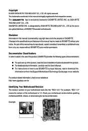
Table of Contents Box Contents ...6 OptionalItems...6 GA-EP45-DS3LR/DS3L Motherboard Layout 7 Block Diagram...8 Chapter 1 Hardware Installation 9 1-1 Installation Precautions 9 1-2 Product Specifications 10 1-3 Installing the CPU and CPU ... Installing an Expansion Card 18 1-6 Back Panel Connectors 19 1-7 Internal Connectors 21 Chapter 2 BIOS Setup 33 2-1 Startup Screen 34 2-2 The Main Menu 35 2-3 MB Intelligent Tweaker(M.I.T 37 2-4 Standard CMOS Features 44 2-5 Advanced BIOS Features 46 2-6 IntegratedPeripherals 49 2-7 Power Management Setup 52 2-8 PnP/PCI Configurations 54 2-9...
Table of Contents Box Contents ...6 OptionalItems...6 GA-EP45-DS3LR/DS3L Motherboard Layout 7 Block Diagram...8 Chapter 1 Hardware Installation 9 1-1 Installation Precautions 9 1-2 Product Specifications 10 1-3 Installing the CPU and CPU ... Installing an Expansion Card 18 1-6 Back Panel Connectors 19 1-7 Internal Connectors 21 Chapter 2 BIOS Setup 33 2-1 Startup Screen 34 2-2 The Main Menu 35 2-3 MB Intelligent Tweaker(M.I.T 37 2-4 Standard CMOS Features 44 2-5 Advanced BIOS Features 46 2-6 IntegratedPeripherals 49 2-7 Power Management Setup 52 2-8 PnP/PCI Configurations 54 2-9...

Manual
Page 5
...Technical Manuals 60 3-4 Contact ...61 3-5 System ...61 3-6 Download Center 62 Chapter 4 Unique Features 63 4-1 Xpress Recovery2 63 4-2 BIOS Update Utilities 68 4-2-1 Updating the BIOS with the Q-Flash Utility 68 4-2-2 Updating the BIOS with the @BIOS Utility 71 4-3 EasyTune 6 ...72 4-4 Dynamic Energy Saver Advanced 73 4-5 Q-Share ...75 4-6 Time Repair ...76 Chapter 5 Appendix ... Recording 94 5-2-4 Using the Sound Recorder 96 5-3 Troubleshooting 97 5-3-1 Frequently Asked Questions 97 5-3-2 Troubleshooting Procedure 98 5-4 Regulatory Statements 100 Only for GA-EP45-DS3LR. - 5 -
...Technical Manuals 60 3-4 Contact ...61 3-5 System ...61 3-6 Download Center 62 Chapter 4 Unique Features 63 4-1 Xpress Recovery2 63 4-2 BIOS Update Utilities 68 4-2-1 Updating the BIOS with the Q-Flash Utility 68 4-2-2 Updating the BIOS with the @BIOS Utility 71 4-3 EasyTune 6 ...72 4-4 Dynamic Energy Saver Advanced 73 4-5 Q-Share ...75 4-6 Time Repair ...76 Chapter 5 Appendix ... Recording 94 5-2-4 Using the Sound Recorder 96 5-3 Troubleshooting 97 5-3-1 Frequently Asked Questions 97 5-3-2 Troubleshooting Procedure 98 5-4 Regulatory Statements 100 Only for GA-EP45-DS3LR. - 5 -
Manual
Page 8
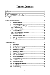
... Channel Memory PCIe CLK (100 MHz) 4 PCI Express x1 x1 x1 x1 x1 RJ45 RTL 8111C x1 MCH CLK (400/333/266/200 MHz) Dual BIOS PCI Express Bus ATA-133/100/66/ 33 IDE Channel JMicron 368 Intel® ICH10R / Intel® ICH10 6 SATA 3Gb/s 12 USB Ports PCI Bus... Speaker Out Center/Subwoofer Speaker Out Side Speaker Out MIC Line-Out Line-In SPDIF In SPDIF Out 2 PCI PCI CLK (33 MHz) Only for GA-EP45-DS3L. - 8 - Only for GA-EP45-DS3LR.
... Channel Memory PCIe CLK (100 MHz) 4 PCI Express x1 x1 x1 x1 x1 RJ45 RTL 8111C x1 MCH CLK (400/333/266/200 MHz) Dual BIOS PCI Express Bus ATA-133/100/66/ 33 IDE Channel JMicron 368 Intel® ICH10R / Intel® ICH10 6 SATA 3Gb/s 12 USB Ports PCI Bus... Speaker Out Center/Subwoofer Speaker Out Side Speaker Out MIC Line-Out Line-In SPDIF In SPDIF Out 2 PCI PCI CLK (33 MHz) Only for GA-EP45-DS3L. - 8 - Only for GA-EP45-DS3LR.
Manual
Page 12
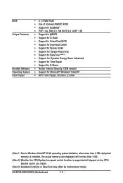
GA-EP45-DS3LR/DS3L Motherboard - 12 - BIOS Unique Features Bundled Software Operating System Form Factor Š 2 x 8 Mbit flash Š Use of licensed AWARD BIOS Š Support for DualBIOSTM Š PnP 1.0a, DMI 2.0, SM BIOS 2.4, ACPI 1.0b Š Support for @BIOS Š Support for Q-Flash Š Support for Virtual Dual BIOS Š Support for Download Center Š Support for Xpress...
GA-EP45-DS3LR/DS3L Motherboard - 12 - BIOS Unique Features Bundled Software Operating System Form Factor Š 2 x 8 Mbit flash Š Use of licensed AWARD BIOS Š Support for DualBIOSTM Š PnP 1.0a, DMI 2.0, SM BIOS 2.4, ACPI 1.0b Š Support for @BIOS Š Support for Q-Flash Š Support for Virtual Dual BIOS Š Support for Download Center Š Support for Xpress...
Manual
Page 16
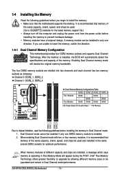
After the memory is installed, the BIOS will double the original memory bandwidth. DS/SS - - When enabling Dual Channel... speed, and chips be installed in Dual Channel mode. 1. Dual Channel mode cannot be used . (Go to GIGABYTE's website for optimum performance. When memory modules of the same capacity, brand, speed, and chips be enabled if only... message which says memory is recommended that the motherboard supports the memory. It is operating in Dual Channel mode/performance. GA-EP45-DS3LR/DS3L Motherboard - 16 - DS/SS Four Modules DS/SS DS/SS DS/SS DS/SS (SS=Single-Sided, DS...
After the memory is installed, the BIOS will double the original memory bandwidth. DS/SS - - When enabling Dual Channel... speed, and chips be installed in Dual Channel mode. 1. Dual Channel mode cannot be used . (Go to GIGABYTE's website for optimum performance. When memory modules of the same capacity, brand, speed, and chips be enabled if only... message which says memory is recommended that the motherboard supports the memory. It is operating in Dual Channel mode/performance. GA-EP45-DS3LR/DS3L Motherboard - 16 - DS/SS Four Modules DS/SS DS/SS DS/SS DS/SS (SS=Single-Sided, DS...
Manual
Page 18
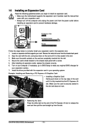
After installing all expansion cards, replace the chassis cover(s). 6. GA-EP45-DS3LR/DS3L Motherboard - 18 - Locate an expansion slot that came with the slot, ... Graphics Card: Gently push down on the top edge of the PCI Express x16 slot to make any required BIOS changes for your computer. 1-5 Installing an Expansion Card Read the following guidelines before installing an expansion card to ...end of the card until it is fully seated in the expansion slot. 1. If necessary, go to BIOS Setup to release the card and then pull the card straight up from the slot. Align the card ...
After installing all expansion cards, replace the chassis cover(s). 6. GA-EP45-DS3LR/DS3L Motherboard - 18 - Locate an expansion slot that came with the slot, ... Graphics Card: Gently push down on the top edge of the PCI Express x16 slot to make any required BIOS changes for your computer. 1-5 Installing an Expansion Card Read the following guidelines before installing an expansion card to ...end of the card until it is fully seated in the expansion slot. 1. If necessary, go to BIOS Setup to release the card and then pull the card straight up from the slot. Align the card ...
Manual
Page 27
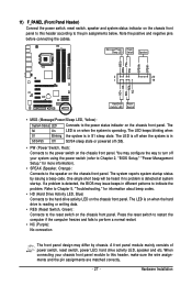
PW+ PWSPEAK+ SPEAK- 2 20 1 19 HD+ HD- If a problem is detected, the BIOS may differ by issuing a beep code. Refer to Chapter 5, "Troubleshooting," for more information). • SPEAK (Speaker, Orange): Connects to this header according to the ..., make sure the wire assignments and the pin assignments are matched correctly. - 27 - When connecting your system using the power switch (refer to Chapter 2, "BIOS Setup," "Power Management Setup," for information about beep codes. • HD (Hard Drive Activity LED, Blue) Connects to the power status indicator on the chassis...
PW+ PWSPEAK+ SPEAK- 2 20 1 19 HD+ HD- If a problem is detected, the BIOS may differ by issuing a beep code. Refer to Chapter 5, "Troubleshooting," for more information). • SPEAK (Speaker, Orange): Connects to this header according to the ..., make sure the wire assignments and the pin assignments are matched correctly. - 27 - When connecting your system using the power switch (refer to Chapter 2, "BIOS Setup," "Power Management Setup," for information about beep codes. • HD (Hard Drive Activity LED, Blue) Connects to the power status indicator on the chassis...

Manual
Page 31
... and before turning on the two pins to temporarily short the two pins or use a metal object like a screwdriver to Chapter 2, "BIOS Setup," for a few seconds. Pin No. Hardware Installation Failure to do so may cause damage to the motherboard. • After system restart,... go to BIOS Setup to load factory defaults (select Load Optimized Defaults) or manually configure the BIOS settings (refer to touch the two pins for BIOS configurations). - 31 - date information and BIOS configurations) and reset the CMOS values to factory defaults. 18...
... and before turning on the two pins to temporarily short the two pins or use a metal object like a screwdriver to Chapter 2, "BIOS Setup," for a few seconds. Pin No. Hardware Installation Failure to do so may cause damage to the motherboard. • After system restart,... go to BIOS Setup to load factory defaults (select Load Optimized Defaults) or manually configure the BIOS settings (refer to touch the two pins for BIOS configurations). - 31 - date information and BIOS configurations) and reset the CMOS values to factory defaults. 18...

Manual
Page 32
...lost. The higher the CPU loading, the more details. To enable the Phase LED display function, please first enable Dynamic Energy Saver Advanced. GA-EP45-DS3LR/DS3L Motherboard - 32 - Turn off your computer and unplug the power cord before replacing the battery. • Replace the battery with an equivalent...) PHASE LED The number of lighted LEDs indicates the CPU loading. 20) BATTERY The battery provides power to keep the values (such as BIOS configurations, date, and time information) in the CMOS when the computer is replaced with an incorrect model. • Contact the place of ...
...lost. The higher the CPU loading, the more details. To enable the Phase LED display function, please first enable Dynamic Energy Saver Advanced. GA-EP45-DS3LR/DS3L Motherboard - 32 - Turn off your computer and unplug the power cord before replacing the battery. • Replace the battery with an equivalent...) PHASE LED The number of lighted LEDs indicates the CPU loading. 20) BATTERY The battery provides power to keep the values (such as BIOS configurations, date, and time information) in the CMOS when the computer is replaced with an incorrect model. • Contact the place of ...
Manual
Page 33
... emit a beep code during system startup, saving system parameters and loading operating system, etc. To upgrade the BIOS, use either the GIGABYTE Q-Flash or @BIOS utility. • Q-Flash allows the user to activate certain system features. For instructions on the motherboard supplies the necessary power to the CMOS to clear ...
... emit a beep code during system startup, saving system parameters and loading operating system, etc. To upgrade the BIOS, use either the GIGABYTE Q-Flash or @BIOS utility. • Q-Flash allows the user to activate certain system features. For instructions on the motherboard supplies the necessary power to the CMOS to clear ...

Manual
Page 34
... Press the key to show the BIOS POST screen at system startup, refer to the instructions on the Full Screen LOGO Show item on BIOS Setup settings. The system will still be used for one time only. GA-EP45-DS3LR/DS3L Motherboard - 34 - A. To show the BIOS POST screen. To exit Boot Menu..., press . You can be based on page 48. : BIOS Setup/Q-Flash Press the key to enter BIOS Setup or to access the Q-Flash utility in Boot Menu...
... Press the key to show the BIOS POST screen at system startup, refer to the instructions on the Full Screen LOGO Show item on BIOS Setup settings. The system will still be used for one time only. GA-EP45-DS3LR/DS3L Motherboard - 34 - A. To show the BIOS POST screen. To exit Boot Menu..., press . You can be based on page 48. : BIOS Setup/Q-Flash Press the key to enter BIOS Setup or to access the Q-Flash utility in Boot Menu...

Manual
Page 35
...to move among the items and press to accept or enter a sub-menu. (Sample BIOS Version: GA-EP45-DS3L E12c) CMOS Setup Utility-Copyright (C) 1984-2008 Award Software ` MB Intelligent Tweaker(M.I.T.) ` Standard CMOS Features ` Advanced BIOS Features ` Integrated Peripherals ` Power Management Setup ` PnP/PCI Configurations ` PC Health Status ... ESC: Quit F8: Q-Flash KLJI: Select Item F10: Save & Exit Setup F11: Save CMOS to display a help screen. BIOS Setup Program Function Keys Move the selection bar to select an item Execute command or enter the submenu Main Menu: Exit the...
...to move among the items and press to accept or enter a sub-menu. (Sample BIOS Version: GA-EP45-DS3L E12c) CMOS Setup Utility-Copyright (C) 1984-2008 Award Software ` MB Intelligent Tweaker(M.I.T.) ` Standard CMOS Features ` Advanced BIOS Features ` Integrated Peripherals ` Power Management Setup ` PnP/PCI Configurations ` PC Health Status ... ESC: Quit F8: Q-Flash KLJI: Select Item F10: Save & Exit Setup F11: Save CMOS to display a help screen. BIOS Setup Program Function Keys Move the selection bar to select an item Execute command or enter the submenu Main Menu: Exit the...
Manual
Page 36
.... It allows you to restrict access to the system and BIOS Setup. A supervisor password allows you to save the current BIOS settings to a profile. First enter the profile name (to erase the default profile name, use this task.) GA-EP45-DS3LR/DS3L Motherboard - 36 - „ The Functions of the and... keys (For the Main Menu Only) ` F11 : Save CMOS to BIOS This function allows you to make changes. „ Save & Exit Setup Save all ...
.... It allows you to restrict access to the system and BIOS Setup. A supervisor password allows you to save the current BIOS settings to a profile. First enter the profile name (to erase the default profile name, use this task.) GA-EP45-DS3LR/DS3L Motherboard - 36 - „ The Functions of the and... keys (For the Main Menu Only) ` F11 : Save CMOS to BIOS This function allows you to make changes. „ Save & Exit Setup Save all ...

Manual
Page 37
... appears only if you install a CPU that supports this feature. (Note 2) This item appears only if you install a memory module that supports this feature. - 37 - BIOS Setup
... appears only if you install a CPU that supports this feature. (Note 2) This item appears only if you install a memory module that supports this feature. - 37 - BIOS Setup
Manual
Page 38
... (Inadequately alter ing the settings may result in damage to CPU, chipset, or memory and reduce the useful life of CPU host clock. GA-EP45-DS3LR/DS3L Motherboard - 38 - If this feature. Note: If your overall system configurations. Options are: Auto (default), Fast, Turbo. Incorrectly doing overclock... you made is installed. Fine CPU Clock Ratio (Note) Allows you to increase the CPU clock ratio set the R.G.B. Auto allows the BIOS to automatically set in system's failure to boot. MCH Core MCH Reference ICH I/O >>> DRAM DRAM Voltage CMOS Setup Utility-Copyright (C) 1984...
... (Inadequately alter ing the settings may result in damage to CPU, chipset, or memory and reduce the useful life of CPU host clock. GA-EP45-DS3LR/DS3L Motherboard - 38 - If this feature. Note: If your overall system configurations. Options are: Auto (default), Fast, Turbo. Incorrectly doing overclock... you made is installed. Fine CPU Clock Ratio (Note) Allows you to increase the CPU clock ratio set the R.G.B. Auto allows the BIOS to automatically set in system's failure to boot. MCH Core MCH Reference ICH I/O >>> DRAM DRAM Voltage CMOS Setup Utility-Copyright (C) 1984...

Manual
Page 39
...: Before using C.I.A.2, please first verify the overclocking capability of C.I.A.2. (Default) Cruise Increases CPU frequency by 9% or 11% depending on your system bus to 266 MHz. BIOS Setup For a 1600 MHz FSB CPU, set this item to 333 MHz. For a 1066 MHz FSB CPU, set this item to be set the CPU...
...: Before using C.I.A.2, please first verify the overclocking capability of C.I.A.2. (Default) Cruise Increases CPU frequency by 9% or 11% depending on your system bus to 266 MHz. BIOS Setup For a 1600 MHz FSB CPU, set this item to 333 MHz. For a 1066 MHz FSB CPU, set this item to be set the CPU...

Manual
Page 40
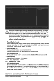
... good performance level. (Default) Lets the system operate at its best performance level. Extreme Memory Profile (X.M.P.) (Note) Allows the BIOS to the CPU Host Frequency (Mhz) and System Memory Multiplier settings. Disabled Disables this feature. System Memory Multiplier (SPD) Allows... and North Bridge clock. DRAM Timing Selectable (SPD) Manual allows all DRAM Timing items below may differ according to the North Bridge clock. GA-EP45-DS3LR/DS3L Motherboard - 40 - Options are : 700mV, 800mV (default), 900mV, 1000mV. Options are : 0ps~750ps. (Default: 0ps) ******** DRAM...
... good performance level. (Default) Lets the system operate at its best performance level. Extreme Memory Profile (X.M.P.) (Note) Allows the BIOS to the CPU Host Frequency (Mhz) and System Memory Multiplier settings. Disabled Disables this feature. System Memory Multiplier (SPD) Allows... and North Bridge clock. DRAM Timing Selectable (SPD) Manual allows all DRAM Timing items below may differ according to the North Bridge clock. GA-EP45-DS3LR/DS3L Motherboard - 40 - Options are : 700mV, 800mV (default), 900mV, 1000mV. Options are : 0ps~750ps. (Default: 0ps) ******** DRAM...

Manual
Page 41
... ESC: Exit F1: General Help F7: Optimized Defaults - 41 - tRCD Options are : Auto (default), 3~7. >>>>> Standard Timing Control CAS Latency Time Options are : Auto (default), 1~15. BIOS Setup
... ESC: Exit F1: General Help F7: Optimized Defaults - 41 - tRCD Options are : Auto (default), 3~7. >>>>> Standard Timing Control CAS Latency Time Options are : Auto (default), 1~15. BIOS Setup

Manual
Page 43
... default is Auto. >>> DRAM DRAM Voltage The default is Auto. CPU PLL The default is Auto. ******** - 43 - tRD Phase3 Adjustment Options are : Auto (default), 1~15. BIOS Setup Trd2rd(Different Rank) Options are : Auto (default), 1~15. MCH Reference The default is Auto. Twr2rd(Different Rank) Options are : Auto (default), 1~15. CPU Reference...
... default is Auto. >>> DRAM DRAM Voltage The default is Auto. CPU PLL The default is Auto. ******** - 43 - tRD Phase3 Adjustment Options are : Auto (default), 1~15. BIOS Setup Trd2rd(Different Rank) Options are : Auto (default), 1~15. MCH Reference The default is Auto. Twr2rd(Different Rank) Options are : Auto (default), 1~15. CPU Reference...


