
Manual
Page 4
... Box Contents ...6 OptionalItems...6 GA-EP43-UD3L/US3L Motherboard Layout 7 Block Diagram...8 Chapter 1 Hardware Installation 9 1-1 Installation Precautions 9 1-2 Product Specifications 10 1-3 Installing the CPU and CPU Cooler 13 1-3-1 Installing the CPU 13 1-3-2 Installing the CPU Cooler 15 1-4 Installing the Memory 16 1-4-1 Dual Channel Memory Configuration 16 1-4-2 Installing a Memory 17 1-5 Installing an Expansion Card 18 1-6 Back Panel Connectors 19 1-7 Internal Connectors 21 Chapter 2 BIOS Setup 33 2-1 Startup Screen 34 2-2 The Main Menu 35 2-3 MB Intelligent Tweaker...
... Box Contents ...6 OptionalItems...6 GA-EP43-UD3L/US3L Motherboard Layout 7 Block Diagram...8 Chapter 1 Hardware Installation 9 1-1 Installation Precautions 9 1-2 Product Specifications 10 1-3 Installing the CPU and CPU Cooler 13 1-3-1 Installing the CPU 13 1-3-2 Installing the CPU Cooler 15 1-4 Installing the Memory 16 1-4-1 Dual Channel Memory Configuration 16 1-4-2 Installing a Memory 17 1-5 Installing an Expansion Card 18 1-6 Back Panel Connectors 19 1-7 Internal Connectors 21 Chapter 2 BIOS Setup 33 2-1 Startup Screen 34 2-2 The Main Menu 35 2-3 MB Intelligent Tweaker...

Manual
Page 10
GA-EP43-UD3L/US3L Motherboard - 10 - 1-2 Product Specifications CPU Front Side Bus Chipset Memory Audio LAN Expansion Slots Storage Interface USB Support for an Intel® CoreTM 2 Extreme processor/ Intel® CoreTM 2 Quad processor/Intel® CoreTM 2 Duo processor/ Intel® Pentium® Dual-Core processor/Intel® Celeron® processor in the LGA 775 package (Go to GIGABYTE's website for the latest CPU support list.) L2 cache varies with CPU 1600(O.C.)/1333/1066/800...
GA-EP43-UD3L/US3L Motherboard - 10 - 1-2 Product Specifications CPU Front Side Bus Chipset Memory Audio LAN Expansion Slots Storage Interface USB Support for an Intel® CoreTM 2 Extreme processor/ Intel® CoreTM 2 Quad processor/Intel® CoreTM 2 Duo processor/ Intel® Pentium® Dual-Core processor/Intel® Celeron® processor in the LGA 775 package (Go to GIGABYTE's website for the latest CPU support list.) L2 cache varies with CPU 1600(O.C.)/1333/1066/800...
Manual
Page 11
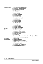
...; 1 x 24-pin ATX main power connector 1 x 4-pin ATX 12V power connector 1 x floppy disk drive connector 1 x IDE connector 6 x SATA 3Gb/s connectors 1 x CPU fan header 2 x system fan headers 1 x power fan header 1 x front panel header 1 x front panel audio header 1 x CD In connector 1 x S/PDIF In header 1 x S/PDIF Out header 2 x USB 2.0/1.1 headers 1 x parallel port header 1 x serial port header 1 x power LED header 1 x chassis...
...; 1 x 24-pin ATX main power connector 1 x 4-pin ATX 12V power connector 1 x floppy disk drive connector 1 x IDE connector 6 x SATA 3Gb/s connectors 1 x CPU fan header 2 x system fan headers 1 x power fan header 1 x front panel header 1 x front panel audio header 1 x CD In connector 1 x S/PDIF In header 1 x S/PDIF Out header 2 x USB 2.0/1.1 headers 1 x parallel port header 1 x serial port header 1 x power LED header 1 x chassis...

Manual
Page 16
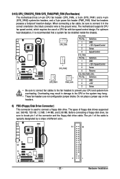
... DDR2 memory sockets are installed, a message which says memory is recommended that the motherboard supports the memory. Dual Channel mode cannot be enabled if only one direction. After the memory is installed. 2. Enabling Dual Channel memory mode will appear during the POST. DS/SS - - - - Intel® Flex Memory Technology offers greater flexibility to upgrade by allowing different memory sizes to insert the memory, switch the direction. 1-4-1 Dual Channel Memory Configuration This motherboard provides four DDR2 memory sockets and supports Dual Channel Technology. DS...
... DDR2 memory sockets are installed, a message which says memory is recommended that the motherboard supports the memory. Dual Channel mode cannot be enabled if only one direction. After the memory is installed. 2. Enabling Dual Channel memory mode will appear during the POST. DS/SS - - - - Intel® Flex Memory Technology offers greater flexibility to upgrade by allowing different memory sizes to insert the memory, switch the direction. 1-4-1 Dual Channel Memory Configuration This motherboard provides four DDR2 memory sockets and supports Dual Channel Technology. DS...

Manual
Page 18
.... 5. PCI Express x1 Slot PCI Express x16 Slot PCI Slot Follow the steps below to install an expansion card: • Make sure the motherboard supports the expansion card. Secure the card's metal bracket to release the card and then pull the card straight up from the chassis back panel. 2. Make sure the card is fully inserted into the slot. 4. GA-EP43-UD3L/US3L Motherboard - 18 - After installing all expansion cards, replace the chassis cover(s). 6. Example: Installing and Removing a PCI Express x16 Graphics Card: • Installing a Graphics Card...
.... 5. PCI Express x1 Slot PCI Express x16 Slot PCI Slot Follow the steps below to install an expansion card: • Make sure the motherboard supports the expansion card. Secure the card's metal bracket to release the card and then pull the card straight up from the chassis back panel. 2. Make sure the card is fully inserted into the slot. 4. GA-EP43-UD3L/US3L Motherboard - 18 - After installing all expansion cards, replace the chassis cover(s). 6. Example: Installing and Removing a PCI Express x16 Graphics Card: • Installing a Graphics Card...
Manual
Page 23
... wire). The motherboard supports CPU fan speed control, which requires the use of floppy disk drives supported are not configuration jumper blocks. For optimum heat dissipation, it in damage to connect a floppy disk drive. Hardware Installation Definition 1 GND 2 +12V 3 Sense • Be sure to connect fan cables to the fan headers to locate pin 1 of the cable is recommended that a system fan be sure to prevent your CPU and system from overheating. 3/4/5) CPU_FAN/SYS_FAN1/SYS_FAN2/PWR_FAN (Fan Headers) The motherboard has a 4-pin CPU fan header (CPU_FAN), a 3-pin...
... wire). The motherboard supports CPU fan speed control, which requires the use of floppy disk drives supported are not configuration jumper blocks. For optimum heat dissipation, it in damage to connect a floppy disk drive. Hardware Installation Definition 1 GND 2 +12V 3 Sense • Be sure to connect fan cables to the fan headers to locate pin 1 of the cable is recommended that a system fan be sure to prevent your CPU and system from overheating. 3/4/5) CPU_FAN/SYS_FAN1/SYS_FAN2/PWR_FAN (Fan Headers) The motherboard has a 4-pin CPU fan header (CPU_FAN), a 3-pin...

Manual
Page 25
... motherboard header. The LED keeps blinking when the system is in Chapter 5, "Configuring 2/4/5.1/7.1-Channel Audio." • Audio signals will make the device unable to this header. Incorrect connection between the module connector and the motherboard header will be used to connect a system power LED on the chassis to Chapter 5, "Configuring 2/4/5.1/7.1-Channel Audio." • Some chassis provide a front panel audio module that has different wire assignments, please contact the chassis manufacturer. - 25 - If your chassis front panel audio module to work...
... motherboard header. The LED keeps blinking when the system is in Chapter 5, "Configuring 2/4/5.1/7.1-Channel Audio." • Audio signals will make the device unable to this header. Incorrect connection between the module connector and the motherboard header will be used to connect a system power LED on the chassis to Chapter 5, "Configuring 2/4/5.1/7.1-Channel Audio." • Some chassis provide a front panel audio module that has different wire assignments, please contact the chassis manufacturer. - 25 - If your chassis front panel audio module to work...

Manual
Page 30
... if the chassis cover has been removed. date information and BIOS configurations) and reset the CMOS values to clear the CMOS values (e.g. Open: Normal Short: Clear CMOS Values • Always turn off your computer, be sure to remove the jumper cap from the jumper. Failure to do so may cause damage to the motherboard. • After system restart, go to BIOS Setup to load factory defaults (select Load Optimized Defaults) or manually configure the BIOS settings (refer...
... if the chassis cover has been removed. date information and BIOS configurations) and reset the CMOS values to clear the CMOS values (e.g. Open: Normal Short: Clear CMOS Values • Always turn off your computer, be sure to remove the jumper cap from the jumper. Failure to do so may cause damage to the motherboard. • After system restart, go to BIOS Setup to load factory defaults (select Load Optimized Defaults) or manually configure the BIOS settings (refer...
Manual
Page 33
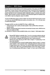
... reset the board to default values. (Refer to the "Load Optimized Defaults" section in this chapter or introductions of the system in the CMOS. BIOS Setup To access the BIOS Setup program, press the key during the POST when the power is recommended that searches and downloads the latest version of the BIOS Setup program. To see more advanced BIOS Setup menu options, you not flash the BIOS. To upgrade the BIOS, use either the GIGABYTE Q-Flash or @BIOS utility. • Q-Flash...
... reset the board to default values. (Refer to the "Load Optimized Defaults" section in this chapter or introductions of the system in the CMOS. BIOS Setup To access the BIOS Setup program, press the key during the POST when the power is recommended that searches and downloads the latest version of the BIOS Setup program. To see more advanced BIOS Setup menu options, you not flash the BIOS. To upgrade the BIOS, use either the GIGABYTE Q-Flash or @BIOS utility. • Q-Flash...

Manual
Page 34
... enter BIOS Setup or to access the Q-Flash utility in Boot Menu. The POST Screen Motherboard Model BIOS Version Award Modular BIOS v6.00PG, An Energy Star Ally Copyright (C) 1984-2008, Award Software, Inc. GA-EP43-UD3L/US3L Motherboard - 34 - EP43-UD3L E3c . . . . Function Keys: : BIOS Setup : XpressRecovery2 : Boot Menu : Qflash 11/27/2008-P43-ICH10-7A69PG0FC-00 Function Keys : POST SCREEN Press the key to show the BIOS POST screen at system startup, refer to the instructions on the Full Screen LOGO Show item on BIOS Setup settings. To exit Boot Menu...
... enter BIOS Setup or to access the Q-Flash utility in Boot Menu. The POST Screen Motherboard Model BIOS Version Award Modular BIOS v6.00PG, An Energy Star Ally Copyright (C) 1984-2008, Award Software, Inc. GA-EP43-UD3L/US3L Motherboard - 34 - EP43-UD3L E3c . . . . Function Keys: : BIOS Setup : XpressRecovery2 : Boot Menu : Qflash 11/27/2008-P43-ICH10-7A69PG0FC-00 Function Keys : POST SCREEN Press the key to show the BIOS POST screen at system startup, refer to the instructions on the Full Screen LOGO Show item on BIOS Setup settings. To exit Boot Menu...

Manual
Page 36
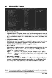
... CPU, memory, etc. Standard CMOS Features Use this menu to configure the system time and date, hard drive types, floppy disk drive types, and the type of errors that stop the system boot, etc. Advanced BIOS Features Use this menu to configure the device boot order, advanced features available on the CPU, and the primary display adapter. Integrated Peripherals Use this menu to configure all peripheral devices, such as IDE, SATA, USB, integrated audio, and integrated LAN, etc. Power Management Setup Use...
... CPU, memory, etc. Standard CMOS Features Use this menu to configure the system time and date, hard drive types, floppy disk drive types, and the type of errors that stop the system boot, etc. Advanced BIOS Features Use this menu to configure the device boot order, advanced features available on the CPU, and the primary display adapter. Integrated Peripherals Use this menu to configure all peripheral devices, such as IDE, SATA, USB, integrated audio, and integrated LAN, etc. Power Management Setup Use...
Manual
Page 38
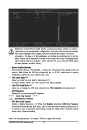
...GA-EP43-UD3L/US3L Motherboard - 38 - Incorrectly doing overclock/overvoltage may result in system's failure to CPU, chipset, or memory and reduce the useful life of these components. Auto allows the BIOS to automatically set in damage to boot. CPU Frequency Displays the current operating CPU frequency. ******** Clock Chip Control Standard Clock Control CPU Host Clock Control Enables or disables the control of the graphics chip and memory. Note: If your overall system configurations. Fine CPU Clock Ratio (Note) Allows you install a CPU that supports this occurs, clear the CMOS...
...GA-EP43-UD3L/US3L Motherboard - 38 - Incorrectly doing overclock/overvoltage may result in system's failure to CPU, chipset, or memory and reduce the useful life of these components. Auto allows the BIOS to automatically set in damage to boot. CPU Frequency Displays the current operating CPU frequency. ******** Clock Chip Control Standard Clock Control CPU Host Clock Control Enables or disables the control of the graphics chip and memory. Note: If your overall system configurations. Fine CPU Clock Ratio (Note) Allows you install a CPU that supports this occurs, clear the CMOS...
Manual
Page 47
... booting the system and for entering the BIOS Setup program. (Default) A password is required every time the system boots, or only when you install a CPU that supports this feature. Capability Enables or disables the S.M.A.R.T. (Self Monitoring and Reporting Technology) capability of your system to move it up or down on the list. Options are: Floppy, LS120, Hard Disk, CDROM, ZIP, USB-FDD, USB-ZIP, USB-CDROM, USB-HDD, Legacy LAN, Disabled. HDD S.M.A.R.T. Capability CPU Multi-Threading (Note) Limit CPUID Max. Use...
... booting the system and for entering the BIOS Setup program. (Default) A password is required every time the system boots, or only when you install a CPU that supports this feature. Capability Enables or disables the S.M.A.R.T. (Self Monitoring and Reporting Technology) capability of your system to move it up or down on the list. Options are: Floppy, LS120, Hard Disk, CDROM, ZIP, USB-FDD, USB-ZIP, USB-CDROM, USB-HDD, Legacy LAN, Disabled. HDD S.M.A.R.T. Capability CPU Multi-Threading (Note) Limit CPUID Max. Use...

Manual
Page 50
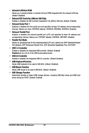
... CMOS Setup Utility-Copyright (C) 1984-2008 Award Software Integrated Peripherals SATA AHCI Mode SATA Port0-3 Native Mode Azalia Codec Onboard H/W LAN Green LAN SMART LAN Onboard LAN Boot ROM Onboard IDE Controller Onboard Serial Port 1 Onboard Parallel Port Parallel Port Mode USB 1.0 Controller USB 2.0 Controller USB Keyboard Function USB Mouse Function USB Storage Function [Disabled] [Disabled] [Auto] [Enabled] [Disbabled] [Press Enter] [Disabled] [Enabled] [3F8/IRQ4] [378/IRQ7] [SPP] [Enabled] [Enabled] [Disabled] [Disabled] [Enabled] Item Help Menu Level Move Enter...
... CMOS Setup Utility-Copyright (C) 1984-2008 Award Software Integrated Peripherals SATA AHCI Mode SATA Port0-3 Native Mode Azalia Codec Onboard H/W LAN Green LAN SMART LAN Onboard LAN Boot ROM Onboard IDE Controller Onboard Serial Port 1 Onboard Parallel Port Parallel Port Mode USB 1.0 Controller USB 2.0 Controller USB Keyboard Function USB Mouse Function USB Storage Function [Disabled] [Disabled] [Auto] [Enabled] [Disbabled] [Press Enter] [Disabled] [Enabled] [3F8/IRQ4] [378/IRQ7] [SPP] [Enabled] [Enabled] [Disabled] [Disabled] [Enabled] Item Help Menu Level Move Enter...
Manual
Page 52
... turn off all of the USB functionalities below. Onboard Parallel Port Enables or disables the onboard parallel port (LPT) and specifies its base I /O address and corresponding interrupt. Options are : 378/IRQ7 (default), 278/IRQ5, 3BC/IRQ7, Disabled. Options are: SPP (Standard Parallel Port)(default), EPP (Enhanced Parallel Port), ECP (Extended Capabilities Port), ECP+EPP. Onboard LAN Boot ROM Allows you to decide whether to detect USB storage devices, including USB flash drives and USB hard drives during the POST. (Default: Enabled) GA-EP43-UD3L/US3L Motherboard...
... turn off all of the USB functionalities below. Onboard Parallel Port Enables or disables the onboard parallel port (LPT) and specifies its base I /O address and corresponding interrupt. Options are : 378/IRQ7 (default), 278/IRQ5, 3BC/IRQ7, Disabled. Options are: SPP (Standard Parallel Port)(default), EPP (Enhanced Parallel Port), ECP (Extended Capabilities Port), ECP+EPP. Onboard LAN Boot ROM Allows you to decide whether to detect USB storage devices, including USB flash drives and USB hard drives during the POST. (Default: Enabled) GA-EP43-UD3L/US3L Motherboard...
Manual
Page 56
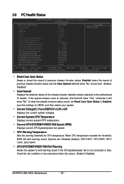
... voltages. If the system chassis cover is not connected or fails. Current CPU/SYSTEM/POWER FAN Speed (RPM) Displays current CPU/system/power fan speed. CPU/SYSTEM/POWER FAN Fail Warning Allows the system to emit warning sound if the CPU/system/power fan is removed, this occurs. (Default: Disabled) GA-EP43-UD3L/US3L Motherboard - 56 - To clear the chassis intrusion status record, set Reset Case Open Status to Enabled, save the settings to CMOS, and then restart your system. When CPU temperature exceeds the threshold, BIOS...
... voltages. If the system chassis cover is not connected or fails. Current CPU/SYSTEM/POWER FAN Speed (RPM) Displays current CPU/system/power fan speed. CPU/SYSTEM/POWER FAN Fail Warning Allows the system to emit warning sound if the CPU/system/power fan is removed, this occurs. (Default: Disabled) GA-EP43-UD3L/US3L Motherboard - 56 - To clear the chassis intrusion status record, set Reset Case Open Status to Enabled, save the settings to CMOS, and then restart your system. When CPU temperature exceeds the threshold, BIOS...

Manual
Page 68
... with the Q-Flash Utility A. Award Modular BIOS v6.00PG, An Energy Star Ally Copyright (C) 1984-2008, Award Software, Inc. What is Q-FlashTM? Extract the file and save the new BIOS file (e.g. Motherboards that matches your computer by either pressing the key during the POST or pressing the key in RAID/AHCI mode or a hard drive attached to an independent IDE/SATA controller, use the key during the POST to your floppy disk, USB flash drive, or hard drive. EP43-UD3L E3c . . . . : BIOS Setup : XpressRecovery2 : Boot Menu : Qflash...
... with the Q-Flash Utility A. Award Modular BIOS v6.00PG, An Energy Star Ally Copyright (C) 1984-2008, Award Software, Inc. What is Q-FlashTM? Extract the file and save the new BIOS file (e.g. Motherboards that matches your computer by either pressing the key during the POST or pressing the key in RAID/AHCI mode or a hard drive attached to an independent IDE/SATA controller, use the key during the POST to your floppy disk, USB flash drive, or hard drive. EP43-UD3L E3c . . . . : BIOS Setup : XpressRecovery2 : Boot Menu : Qflash...
Manual
Page 69
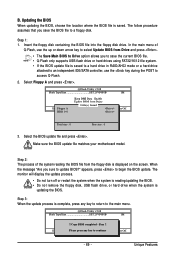
... Enable !! Select Floppy A and press . Step 3: When the update process is saved to a hard drive in RAID/AHCI mode or a hard drive attached to an independent IDE/SATA controller, use the up or down arrow key to select Update BIOS from Drive Sa0vefilBeI(Os)SfotounDdrive :Move ESC:Reset :Power Off Total size : 0 Free size : 0 3. CoUpypdBaItOe SBIcOomS pfrloetmedD-rPivaess !! Unique Features B. When the message "Are you to save the BIOS file to access Q-Flash. 2. The monitor will display...
... Enable !! Select Floppy A and press . Step 3: When the update process is saved to a hard drive in RAID/AHCI mode or a hard drive attached to an independent IDE/SATA controller, use the up or down arrow key to select Update BIOS from Drive Sa0vefilBeI(Os)SfotounDdrive :Move ESC:Reset :Power Off Total size : 0 Free size : 0 3. CoUpypdBaItOe SBIcOomS pfrloetmedD-rPivaess !! Unique Features B. When the message "Are you to save the BIOS file to access Q-Flash. 2. The monitor will display...

Manual
Page 72
.../ Pentium Dual-Core/ Celeron Dual-Core Series CPU and DDR2 800 MHz memory module(s) (or above) to be changed linearly based on the installed CPU and motherboard. After making changes in EasyTune 6 may differ by motherboard model. The Graphics tab allows you to change system clock settings and voltages settings using the sliders. • Save allows you to save the current settings to a new profile (.txt file). • Load allows you to load previous settings from...
.../ Pentium Dual-Core/ Celeron Dual-Core Series CPU and DDR2 800 MHz memory module(s) (or above) to be changed linearly based on the installed CPU and motherboard. After making changes in EasyTune 6 may differ by motherboard model. The Graphics tab allows you to change system clock settings and voltages settings using the sliders. • Save allows you to save the current settings to a new profile (.txt file). • Load allows you to load previous settings from...

Manual
Page 84
... the jumper to the Support\Motherboard\FAQ page on the motherboard battery in the BIOS Setup program. A: The following Award BIOS beep code descriptions may help you identify possible computer problems. (For reference only.) 1 short: System boots successfully 2 short: CMOS setting error 1 long, 1 short: Memory or motherboard error 1 long, 2 short: Monitor or graphics card error 1 long, 3 short: Keyboard error 1 long, 9 short: BIOS ROM error Continuous long beeps: Graphics card not inserted properly Continuous short beeps: Power error GA-EP43-UD3L/US3L Motherboard - 84 - Turn off...
... the jumper to the Support\Motherboard\FAQ page on the motherboard battery in the BIOS Setup program. A: The following Award BIOS beep code descriptions may help you identify possible computer problems. (For reference only.) 1 short: System boots successfully 2 short: CMOS setting error 1 long, 1 short: Memory or motherboard error 1 long, 2 short: Monitor or graphics card error 1 long, 3 short: Keyboard error 1 long, 9 short: BIOS ROM error Continuous long beeps: Graphics card not inserted properly Continuous short beeps: Power error GA-EP43-UD3L/US3L Motherboard - 84 - Turn off...


