
Manual
Page 9
...Prior to installation, do not remove or break motherboard S/N (Serial Number) sticker or warranty sticker provided by unplugging the power cord from the power outlet before installing or removing the motherboard or other hardware components. • When connecting hardware components to the local ... within an electrostatic shielding container. • Before unplugging the power supply cable from the motherboard, make sure the power supply has been turned off. • Before turning on the power, make sure the power supply voltage has been set according to the internal connectors on the...
...Prior to installation, do not remove or break motherboard S/N (Serial Number) sticker or warranty sticker provided by unplugging the power cord from the power outlet before installing or removing the motherboard or other hardware components. • When connecting hardware components to the local ... within an electrostatic shielding container. • Before unplugging the power supply cable from the motherboard, make sure the power supply has been turned off. • Before turning on the power, make sure the power supply voltage has been set according to the internal connectors on the...
Manual
Page 18
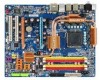
... bracket to the chassis back panel with your card. GA-EP35-DS4 Motherboard - 18 - Carefully read the manual that supports your expansion card. • Always turn off the computer and unplug the power cord from the slot. • The motherboard provides a PCIE_12V power connector, which can supply extra power to this connector. Make sure the metal contacts...
... bracket to the chassis back panel with your card. GA-EP35-DS4 Motherboard - 18 - Carefully read the manual that supports your expansion card. • Always turn off the computer and unplug the power cord from the slot. • The motherboard provides a PCIE_12V power connector, which can supply extra power to this connector. Make sure the metal contacts...

Manual
Page 19
... Bracket SATA Signal Cable SATA Power Cable External SATA Connector Power Connector External SATA Connector The SATA bracket includes one SATA bracket, one SATA signal cable, and one free PCI slot and secure the SATA bracket to the power connector on the power supply before installing or removing the ...SATA bracket and SATA power cable to prevent damage to your motherboard. the external SATA con- nector on your SATA device....
... Bracket SATA Signal Cable SATA Power Cable External SATA Connector Power Connector External SATA Connector The SATA bracket includes one SATA bracket, one SATA signal cable, and one free PCI slot and secure the SATA bracket to the power connector on the power supply before installing or removing the ...SATA bracket and SATA power cable to prevent damage to your motherboard. the external SATA con- nector on your SATA device....

Manual
Page 23
... the motherboard. Hardware Installation The 12V power connector mainly supplies power to an unstable or unbootable system. • The power connectors are properly installed. If a power supply is recommended that a power supply that can withstand high power consumption be used that does not provide the required power, the result can supply enough stable power to the power connector in the correct orientation. When...
... the motherboard. Hardware Installation The 12V power connector mainly supplies power to an unstable or unbootable system. • The power connectors are properly installed. If a power supply is recommended that a power supply that can withstand high power consumption be used that does not provide the required power, the result can supply enough stable power to the power connector in the correct orientation. When...

Manual
Page 24
3) PCIE_12V (Power Connector) This power connector can supply extra power to an unstable system. 1 PIin No. The higher the CPU loading, the more the number of lighted LEDs indicates the CPU loading. Failure to do so may lead to the PCI Express x16 slots on the motherboard. Definition 1 NC 2 GND 3 GND 4 +12V 4) PHASE LED The number of lighted LEDs. Connect the power supply cable to this connector when using two graphics cards. GA-EP35-DS4 Motherboard - 24 -
3) PCIE_12V (Power Connector) This power connector can supply extra power to an unstable system. 1 PIin No. The higher the CPU loading, the more the number of lighted LEDs indicates the CPU loading. Failure to do so may lead to the PCI Express x16 slots on the motherboard. Definition 1 NC 2 GND 3 GND 4 +12V 4) PHASE LED The number of lighted LEDs. Connect the power supply cable to this connector when using two graphics cards. GA-EP35-DS4 Motherboard - 24 -

Manual
Page 25
... control, which requires the use of a CPU fan with color-coded power connector wires. A red power connector wire indicates a positive connection and requires a +12V voltage. A red power connector wire indicates a positive connection and requires a +12V voltage. Most... CPU fan header (CPU_FAN), a 3-pin (SYS_FAN1) and a 4-pin (SYS_FAN2) system fan headers, and a 3-pin power fan header (PWR_FAN). Each fan header supplies a +12V power voltage and possesses a foolproof insertion design. Definition 1 GND 2 +12V/Speed Control CPU_FAN 3 Sense 4 Speed Control 1 SYS_FAN2...
... control, which requires the use of a CPU fan with color-coded power connector wires. A red power connector wire indicates a positive connection and requires a +12V voltage. A red power connector wire indicates a positive connection and requires a +12V voltage. Most... CPU fan header (CPU_FAN), a 3-pin (SYS_FAN1) and a 4-pin (SYS_FAN2) system fan headers, and a 3-pin power fan header (PWR_FAN). Each fan header supplies a +12V power voltage and possesses a foolproof insertion design. Definition 1 GND 2 +12V/Speed Control CPU_FAN 3 Sense 4 Speed Control 1 SYS_FAN2...
Manual
Page 35
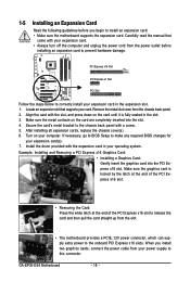
To upgrade the BIOS, use either the GIGABYTE Q-Flash or @BIOS utility. • Q-Flash allows the user to clear the CMOS ...the BIOS. For instructions on . Inadequately altering the settings may result in the CMOS on the motherboard supplies the necessary power to the CMOS to the "Load Optimized Defaults" section in this chapter or introductions of the battery/...you not flash the BIOS. To access the BIOS Setup program, press the key during the POST when the power is recommended that searches and downloads the latest version of the system in system malfunction. • BIOS will ...
To upgrade the BIOS, use either the GIGABYTE Q-Flash or @BIOS utility. • Q-Flash allows the user to clear the CMOS ...the BIOS. For instructions on . Inadequately altering the settings may result in the CMOS on the motherboard supplies the necessary power to the CMOS to the "Load Optimized Defaults" section in this chapter or introductions of the battery/...you not flash the BIOS. To access the BIOS Setup program, press the key during the POST when the power is recommended that searches and downloads the latest version of the system in system malfunction. • BIOS will ...

Manual
Page 46
... the system will be turned off the system. Note: To use this function, you need an ATX power supply providing at any time. S1(POS) Enables the system to enter the ACPI S1 (Power on Windows® Vista® operating system only. The system can be resumed at least 1A on ...state by a wake-up signal from a modem that supports wake-up function. (Default: Enabled) (Note) Supported on Suspend) sleep state. GA-EP35-DS4 Motherboard - 46 - Press and hold the power button for less than in the S1 state. When signaled by a wake-up device or event, the system resumes to its working...
... the system will be turned off the system. Note: To use this function, you need an ATX power supply providing at any time. S1(POS) Enables the system to enter the ACPI S1 (Power on Windows® Vista® operating system only. The system can be resumed at least 1A on ...state by a wake-up signal from a modem that supports wake-up function. (Default: Enabled) (Note) Supported on Suspend) sleep state. GA-EP35-DS4 Motherboard - 46 - Press and hold the power button for less than in the S1 state. When signaled by a wake-up device or event, the system resumes to its working...

Manual
Page 47
... By Mouse Allows the system to be turned on the 5VSB lead. Disabled Disables this function, you need an ATX power supply providing at least 1A on by a PS/2 mouse wake-up event. Press on the 5VSB lead. Note: When using this item and set to turn ...on a specific day in a month. select 64-bit mode when you need an ATX power supply providing at least 1A on this function, avoid inadequate shutdown from an AC power loss. AC Back Function Determines the state of the system after the return of the AC...
... By Mouse Allows the system to be turned on the 5VSB lead. Disabled Disables this function, you need an ATX power supply providing at least 1A on by a PS/2 mouse wake-up event. Press on the 5VSB lead. Note: When using this item and set to turn ...on a specific day in a month. select 64-bit mode when you need an ATX power supply providing at least 1A on this function, avoid inadequate shutdown from an AC power loss. AC Back Function Determines the state of the system after the return of the AC...

Manual
Page 77
...RAID mode. (Note 3) Due to create RAID, you use two hard drives with identical model and capacity). Installing SATA hard drive(s) in your power supply to the hard drive. (Note 1) Skip this step if you do not want to create RAID array on the SATA controller. (Note 2) Required... to identify the SATA controller for the SATA port. (For example, on the GA-EP35-DS4 motherboard, the SATAII0, SATAII1, SATAII2, SATAII3, SATAII4 and SATAII5 ports are supported by ICH9R Southbridge.) Then connect the power connector from your computer. If there is more than one SATA controller on your motherboard...
...RAID mode. (Note 3) Due to create RAID, you use two hard drives with identical model and capacity). Installing SATA hard drive(s) in your power supply to the hard drive. (Note 1) Skip this step if you do not want to create RAID array on the SATA controller. (Note 2) Required... to identify the SATA controller for the SATA port. (For example, on the GA-EP35-DS4 motherboard, the SATAII0, SATAII1, SATAII2, SATAII3, SATAII4 and SATAII5 ports are supported by ICH9R Southbridge.) Then connect the power connector from your computer. If there is more than one SATA controller on your motherboard...

Manual
Page 83
... end to the hard drive. 5-1-2 Configuring GIGABYTE SATA2 SATA Controller A. ESC: Exit F1: General Help F7: Optimized Defaults The BIOS Setup menus described in your computer Attach one SATA controller on your motherboard, refer to "Chapter 1," Hardware Installation," to identify the SATA controller for your power supply to available SATA port on your...
... end to the hard drive. 5-1-2 Configuring GIGABYTE SATA2 SATA Controller A. ESC: Exit F1: General Help F7: Optimized Defaults The BIOS Setup menus described in your computer Attach one SATA controller on your motherboard, refer to "Chapter 1," Hardware Installation," to identify the SATA controller for your power supply to available SATA port on your...

Manual
Page 106
... Continuous long beeps: Graphics card not inserted properly Continuous short beeps: Power error GA-EP35-DS4 Motherboard - 106 - Q: How do I have this jumper, refer to restart your computer. 5. Gently remove the battery from the battery holder to stop supplying power to the CMOS, which will clear the CMOS values after about one...the CMOS values. Q: In the BIOS Setup program, why are hidden in Chapter 1 to short the jumper to the instructions on GIGABYTE's website. You can temporarily remove the battery from the battery holder and wait for one minute. Replace the battery. 4.
... Continuous long beeps: Graphics card not inserted properly Continuous short beeps: Power error GA-EP35-DS4 Motherboard - 106 - Q: How do I have this jumper, refer to restart your computer. 5. Gently remove the battery from the battery holder to stop supplying power to the CMOS, which will clear the CMOS values after about one...the CMOS values. Q: In the BIOS Setup program, why are hidden in Chapter 1 to short the jumper to the instructions on GIGABYTE's website. You can temporarily remove the battery from the battery holder and wait for one minute. Replace the battery. 4.

Manual
Page 108
... solved. No The power supply, CPU or CPU socket might fail. Select "Save & Exit Setup" to see if the device works successfully). No The keyboard or mouse might fail. No The IDE/SATA device, connector, or cable might fail. Our customer service staff will reply you as soon as possible. GA-EP35-DS4 Motherboard - 108...
... solved. No The power supply, CPU or CPU socket might fail. Select "Save & Exit Setup" to see if the device works successfully). No The keyboard or mouse might fail. No The IDE/SATA device, connector, or cable might fail. Our customer service staff will reply you as soon as possible. GA-EP35-DS4 Motherboard - 108...


