Manual
Page 5
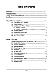
Table of Contents ItemChecklist ...7 OptionalAccessories ...7 GA-965P-DS3/S3 Motherboard Layout 8 Block Diagram ...9 Chapter 1 Hardware Installation 11 1-1 Considerations Prior to Installation 11 1-2 Feature Summary 12 1-3 ... 16 1-5 Installation of Expansion Cards 18 1-6 I/O Back Panel Introduction 19 1-7 Connectors Introduction 20 Chapter 2 BIOS Setup 31 The Main Menu (Example BIOS Ver.: GA-965P-DS3, F10a 32 2-1 Standard CMOS Features 34 2-2 Advanced BIOS Features 36 2-3 IntegratedPeripherals 38 2-4 Power Management Setup 41 2-5 PnP/PCI Configurations 43 2-6 PC Health Status ...
Table of Contents ItemChecklist ...7 OptionalAccessories ...7 GA-965P-DS3/S3 Motherboard Layout 8 Block Diagram ...9 Chapter 1 Hardware Installation 11 1-1 Considerations Prior to Installation 11 1-2 Feature Summary 12 1-3 ... 16 1-5 Installation of Expansion Cards 18 1-6 I/O Back Panel Introduction 19 1-7 Connectors Introduction 20 Chapter 2 BIOS Setup 31 The Main Menu (Example BIOS Ver.: GA-965P-DS3, F10a 32 2-1 Standard CMOS Features 34 2-2 Advanced BIOS Features 36 2-3 IntegratedPeripherals 38 2-4 Power Management Setup 41 2-5 PnP/PCI Configurations 43 2-6 PC Health Status ...

Manual
Page 6
Channel Audio Function Introduction 77 4-2 Troubleshooting 82 - 6 - Chapter 3 Install Drivers 53 3-1 Install Chipset Drivers 53 3-2 SoftwareApplications 54 3-3 Driver CD Information 54 3-4 Hardware Information 55 3-5 Contact Us ...55 Chapter 4 Appendix 57 4-1 Unique Software Utilities 57 4-1-1 EasyTune 5 Introduction 57 4-1-2 Xpress Recovery2 Introduction 58 4-1-3 Flash BIOS Method Introduction 60 4-1-4 Configuring SATA Hard Drive(s) (Controller: GIGABYTE SATA2 64 4-1-5 2- / 4- / 6- / 8-
Channel Audio Function Introduction 77 4-2 Troubleshooting 82 - 6 - Chapter 3 Install Drivers 53 3-1 Install Chipset Drivers 53 3-2 SoftwareApplications 54 3-3 Driver CD Information 54 3-4 Hardware Information 55 3-5 Contact Us ...55 Chapter 4 Appendix 57 4-1 Unique Software Utilities 57 4-1-1 EasyTune 5 Introduction 57 4-1-2 Xpress Recovery2 Introduction 58 4-1-3 Flash BIOS Method Introduction 60 4-1-4 Configuring SATA Hard Drive(s) (Controller: GIGABYTE SATA2 64 4-1-5 2- / 4- / 6- / 8-
Manual
Page 8
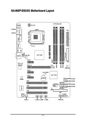
GA-965P-DS3/S3 Motherboard Layout KB_MS COAXIAL OPTICAL ATX_12V LGA775 CPU_FAN ATX COM LPT SYS_FAN GA-965P-DS3/S3 DDRII1 USB USB LAN F_AUDIO AUDIO NB_FAN Marvell 88E8056 PCIE_3 PCIE_16 PCIE_1 CODEC PCIE_2 PCI1 PCI2 IT8718 PCI3 CD_IN Intel® P965 FDD DDRII3 DDRII4 DDRII2 PWR_FAN CLR_CMOS BATTERY Intel® ICH8 GSATAII0 GIGABYTE SATA2 GSATAII1 BIOS IDE1 CI F_PANEL SATAII0 SATAII1 SATAII2 SATAII3 SPDIF_I F_USB1 F_USB2 F_USB3 PWR_LED - 8 -
GA-965P-DS3/S3 Motherboard Layout KB_MS COAXIAL OPTICAL ATX_12V LGA775 CPU_FAN ATX COM LPT SYS_FAN GA-965P-DS3/S3 DDRII1 USB USB LAN F_AUDIO AUDIO NB_FAN Marvell 88E8056 PCIE_3 PCIE_16 PCIE_1 CODEC PCIE_2 PCI1 PCI2 IT8718 PCI3 CD_IN Intel® P965 FDD DDRII3 DDRII4 DDRII2 PWR_FAN CLR_CMOS BATTERY Intel® ICH8 GSATAII0 GIGABYTE SATA2 GSATAII1 BIOS IDE1 CI F_PANEL SATAII0 SATAII1 SATAII2 SATAII3 SPDIF_I F_USB1 F_USB2 F_USB3 PWR_LED - 8 -
Manual
Page 9
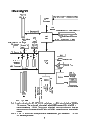
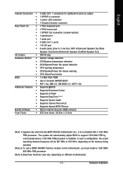
In such a configuration, the actual operating memory frequency will automatically adjust BIOS to support 1333 MHz FSB by overclocking when a 1333 MHz FSB...266/200/133 MHz) PCI Express x16 2 SATA 3Gb/s LAN ATA 33/66/100/133 RJ45 IDE Channel GIGABYTE Marvell SATA2 88E8056 x1 PCI Express Bus x1 x1 x1 x1 PCIe CLK (100 MHz) 3 PCI Express ...BIOS 4 SATA 3Gb/s 10 USB Ports IT8718 LPT Port Floppy COM Port PS/2 KB/Mouse Center/Subwoofer Speaker Out Surround Speaker Out Side Speaker Out MIC Line-Out Line-In SPDIF In SPDIF Out 3 PCI PCICLK (33 MHz) (Note 1) Applies only when the GA-965P-DS3...
In such a configuration, the actual operating memory frequency will automatically adjust BIOS to support 1333 MHz FSB by overclocking when a 1333 MHz FSB...266/200/133 MHz) PCI Express x16 2 SATA 3Gb/s LAN ATA 33/66/100/133 RJ45 IDE Channel GIGABYTE Marvell SATA2 88E8056 x1 PCI Express Bus x1 x1 x1 x1 PCIe CLK (100 MHz) 3 PCI Express ...BIOS 4 SATA 3Gb/s 10 USB Ports IT8718 LPT Port Floppy COM Port PS/2 KB/Mouse Center/Subwoofer Speaker Out Surround Speaker Out Side Speaker Out MIC Line-Out Line-In SPDIF In SPDIF Out 3 PCI PCICLK (33 MHz) (Note 1) Applies only when the GA-965P-DS3...
Manual
Page 13
...CPU/System/Power fan failure warning Š CPU Smart Fan Control BIOS Š 1 8 Mbit flash ROM Š Use of licensed AWARD BIOS Š PnP 1.0a, DMI 2.0, SM BIOS 2.3, ACPI 1.0b Additional Features Š Supports @BIOS Š Supports Download Center Š Supports Q-Flash Š Supports... Š Supports Xpress Recovery2 Š Supports Xpress BIOS Rescue Bundle Software Š Norton Internet Security (OEM revision) Form Factor Š ATX form factor; 30.5cm x 21.0cm (Note 1) Applies only when the GA-965P-DS3/S3 motherboard (rev. 3.3) is installed. Hardware Installation...
...CPU/System/Power fan failure warning Š CPU Smart Fan Control BIOS Š 1 8 Mbit flash ROM Š Use of licensed AWARD BIOS Š PnP 1.0a, DMI 2.0, SM BIOS 2.3, ACPI 1.0b Additional Features Š Supports @BIOS Š Supports Download Center Š Supports Q-Flash Š Supports... Š Supports Xpress Recovery2 Š Supports Xpress BIOS Rescue Bundle Software Š Norton Internet Security (OEM revision) Form Factor Š ATX form factor; 30.5cm x 21.0cm (Note 1) Applies only when the GA-965P-DS3/S3 motherboard (rev. 3.3) is installed. Hardware Installation...
Manual
Page 14
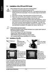
... with HT Technology - BIOS: A BIOS that might cause damage to set the CPU host frequency in a straight and downwards motion. Avoid twisting or bending motions that supports HT Technology and has it does not meet the required standards for the peripherals. If you wish to the CPU during installation.) GA-965P-DS3/S3 Motherboard - 14...
... with HT Technology - BIOS: A BIOS that might cause damage to set the CPU host frequency in a straight and downwards motion. Avoid twisting or bending motions that supports HT Technology and has it does not meet the required standards for the peripherals. If you wish to the CPU during installation.) GA-965P-DS3/S3 Motherboard - 14...
Manual
Page 16
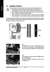
...foolproof insertion design. The memory capacity used is switched off to lock the DIMM module. The motherboard supports DDRII memory modules, whereby BIOS will automatically detect memory capacity and specifications. Insert the DIMM memory module vertically into the DIMM socket. English 1-4 Installation of Memory ... Then push it down. Reverse the installation steps when you are designed so that the memory used can only fit in one direction. GA-965P-DS3/S3 Motherboard - 16 - Notch DDRII Fig.1 The DIMM socket has a notch, so the DIMM memory module can differ with the...
...foolproof insertion design. The memory capacity used is switched off to lock the DIMM module. The motherboard supports DDRII memory modules, whereby BIOS will automatically detect memory capacity and specifications. Insert the DIMM memory module vertically into the DIMM socket. English 1-4 Installation of Memory ... Then push it down. Reverse the installation steps when you are designed so that the memory used can only fit in one direction. GA-965P-DS3/S3 Motherboard - 16 - Notch DDRII Fig.1 The DIMM socket has a notch, so the DIMM memory module can differ with the...
Manual
Page 18
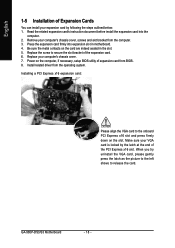
...to the onboard PCI Express x16 slot and press firmly down on the card are indeed seated in motherboard. 4. GA-965P-DS3/S3 Motherboard - 18 - Power on the computer, if necessary, setup BIOS utility of the expansion card. 6. When you try uninstall the VGA card, please gently press the latch as... the picture to the left shows to secure the slot bracket of expansion card from BIOS. 8. Be sure the metal contacts on the slot. Press the expansion card firmly into the computer. 2. Read the related expansion card's ...
...to the onboard PCI Express x16 slot and press firmly down on the card are indeed seated in motherboard. 4. GA-965P-DS3/S3 Motherboard - 18 - Power on the computer, if necessary, setup BIOS utility of the expansion card. 6. When you try uninstall the VGA card, please gently press the latch as... the picture to the left shows to secure the slot bracket of expansion card from BIOS. 8. Be sure the metal contacts on the slot. Press the expansion card firmly into the computer. 2. Read the related expansion card's ...
Manual
Page 24
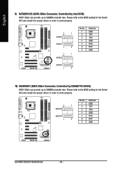
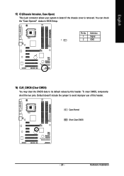
Please refer to the BIOS setting for the Serial ATA and install the proper driver in order to work properly. 7 1 SATAII0 SATAII1 1 7 7 1 SATAII2 Pin No. 1 2 3 4 5 6 7 Definition GND TXP TXN GND ... 300MB/s transfer rate. Please refer to the BIOS setting for the Serial ATA and install the proper driver in order to work properly. 7 1 GSATAII0 GSATAII1 1 7 Pin No. 1 2 3 4 5 6 7 Definition GND TXP TXN GND RXN RXP GND GA-965P-DS3/S3 Motherboard - 24 - English 9) SATAII0/1/2/3 (SATA 3Gb/s Connector, Controlled by GIGABYTE SATA2) SATA 3Gb/s can provide up...
Please refer to the BIOS setting for the Serial ATA and install the proper driver in order to work properly. 7 1 SATAII0 SATAII1 1 7 7 1 SATAII2 Pin No. 1 2 3 4 5 6 7 Definition GND TXP TXN GND ... 300MB/s transfer rate. Please refer to the BIOS setting for the Serial ATA and install the proper driver in order to work properly. 7 1 GSATAII0 GSATAII1 1 7 Pin No. 1 2 3 4 5 6 7 Definition GND TXP TXN GND RXN RXP GND GA-965P-DS3/S3 Motherboard - 24 - English 9) SATAII0/1/2/3 (SATA 3Gb/s Connector, Controlled by GIGABYTE SATA2) SATA 3Gb/s can provide up...
Manual
Page 29
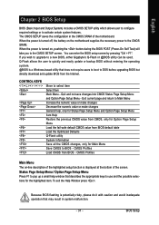
Pin No. Default doesn't include the jumper to avoid improper use of this header. Hardware Installation Definition 1 Signal 1 2 GND 18) CLR_CMOS (Clear CMOS) You may clear the CMOS data to detect if the chassis cover is removed. To clear CMOS, temporarily short the two pins. Open: Normal Short: Clear CMOS - 29 - English 17) CI (Chassis Intrusion, Case Open) This 2-pin connector allows your system to its default values by this header. You can check the "Case Opened" status in BIOS Setup.
Pin No. Default doesn't include the jumper to avoid improper use of this header. Hardware Installation Definition 1 Signal 1 2 GND 18) CLR_CMOS (Clear CMOS) You may clear the CMOS data to detect if the chassis cover is removed. To clear CMOS, temporarily short the two pins. Open: Normal Short: Clear CMOS - 29 - English 17) CI (Chassis Intrusion, Case Open) This 2-pin connector allows your system to its default values by this header. You can check the "Case Opened" status in BIOS Setup.
Manual
Page 31
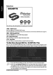
... do it with caution and avoid inadequate operation that describes the appropriate keys to use and the possible selections for Main Menu Save CMOS to BIOS - BIOS Setup The CMOS SETUP saves the configuration in system malfunction. - 31 - To exit the Help Window press . You can be used.... CMOS Profiles Main Menu The on the motherboard supplies the necessary power to a new BIOS, either Gigabyte's Q-Flash or @BIOS utility can enter the BIOS setup screen by pressing "Ctrl + F1". When the power is turned off, the battery on -line description of the ...
... do it with caution and avoid inadequate operation that describes the appropriate keys to use and the possible selections for Main Menu Save CMOS to BIOS - BIOS Setup The CMOS SETUP saves the configuration in system malfunction. - 31 - To exit the Help Window press . You can be used.... CMOS Profiles Main Menu The on the motherboard supplies the necessary power to a new BIOS, either Gigabyte's Q-Flash or @BIOS utility can enter the BIOS setup screen by pressing "Ctrl + F1". When the power is turned off, the battery on -line description of the ...
Manual
Page 32
... the F12 key to enter Boot Menu to select the first boot device. GA-965P-DS3/S3 Motherboard - 32 - Use arrow keys to select among the items and press to accept or enter the sub-menu. Startup Screen: English : POST Screen : BIOS Setup/Q-Flash : XpressRecovery2 : Boot Menu : POST Screen Press the TAB key ...the Full Screen LOGO Show item on the screen. Select the Load Optimized Defaults item in this chapter are for stability. 3. The Main Menu (Example BIOS Ver.: GA-965P-DS3, F10a) Once you want, press "Ctrl+F1" to the default settings for reference only and may differ from...
... the F12 key to enter Boot Menu to select the first boot device. GA-965P-DS3/S3 Motherboard - 32 - Use arrow keys to select among the items and press to accept or enter the sub-menu. Startup Screen: English : POST Screen : BIOS Setup/Q-Flash : XpressRecovery2 : Boot Menu : POST Screen Press the TAB key ...the Full Screen LOGO Show item on the screen. Select the Load Optimized Defaults item in this chapter are for stability. 3. The Main Menu (Example BIOS Ver.: GA-965P-DS3, F10a) Once you want, press "Ctrl+F1" to the default settings for reference only and may differ from...
Manual
Page 33
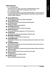
...; Save & Exit Setup Save CMOS value settings to make a record of the current CMOS settings as a profile. English BIOS Setting Recovery F11 : Save CMOS to BIOS This function allows you to CMOS and exit setup. „ Exit Without Saving Abandon all the configurations of PCI & PnP.... „ Load Optimized Defaults Optimized Defaults indicates the value of the system parameters which the system would be in standard compatible BIOS. „ Advanced BIOS Features This setup page includes all the items of Award special enhanced features. „ Integrated Peripherals This setup page includes all ...
...; Save & Exit Setup Save CMOS value settings to make a record of the current CMOS settings as a profile. English BIOS Setting Recovery F11 : Save CMOS to BIOS This function allows you to CMOS and exit setup. „ Exit Without Saving Abandon all the configurations of PCI & PnP.... „ Load Optimized Defaults Optimized Defaults indicates the value of the system parameters which the system would be in standard compatible BIOS. „ Advanced BIOS Features This setup page includes all the items of Award special enhanced features. „ Integrated Peripherals This setup page includes all ...
Manual
Page 34
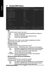
... 1 to 31 (or the maximum allowed in the month) Year The year, from Sun to Sat, determined by the BIOS and is calculated base on the 24-hour military-time clock. is , , , . GA-965P-DS3/S3 Motherboard - 34 - English 2-1 Standard CMOS Features Date (mm:dd:yy) Time (hh:mm:ss) CMOS Setup... manually input the correct settings Access Mode Use this option for automatic device detection. You can use one of three methods: Auto Allows BIOS to select this if no IDE/SATA devices are used and the system will skip the automatic detection step and allow for faster system ...
... 1 to 31 (or the maximum allowed in the month) Year The year, from Sun to Sat, determined by the BIOS and is calculated base on the 24-hour military-time clock. is , , , . GA-965P-DS3/S3 Motherboard - 34 - English 2-1 Standard CMOS Features Date (mm:dd:yy) Time (hh:mm:ss) CMOS Setup... manually input the correct settings Access Mode Use this option for automatic device detection. You can use one of three methods: Auto Allows BIOS to select this if no IDE/SATA devices are used and the system will skip the automatic detection step and allow for faster system ...
Manual
Page 35
...Drive. Floppy 3 Mode Support (for a disk error; All, But Keyboard The system boot will stop for a keyboard error; Base Memory The POST of the BIOS will be stopped. None 360K, 5.25" No floppy drive installed 5.25 inch PC-type standard drive; 360K byte capacity. 1.2M, 5.25" 5.25 inch ...This item displays the memory size that may be detected and you All Errors will determine the amount of currently installed hard disk. Whenever the BIOS detects a non-fatal error the system will stop for Japan Area) Disabled Normal Floppy Drive. (Default value) Drive A Drive A is present ...
...Drive. Floppy 3 Mode Support (for a disk error; All, But Keyboard The system boot will stop for a keyboard error; Base Memory The POST of the BIOS will be stopped. None 360K, 5.25" No floppy drive installed 5.25 inch PC-type standard drive; 360K byte capacity. 1.2M, 5.25" 5.25 inch ...This item displays the memory size that may be detected and you All Errors will determine the amount of currently installed hard disk. Whenever the BIOS detects a non-fatal error the system will stop for Japan Area) Disabled Normal Floppy Drive. (Default value) Drive A Drive A is present ...
Manual
Page 36
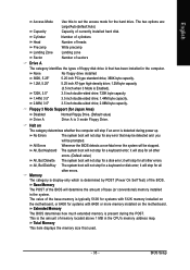
...: Optimized Defaults Hard Disk Boot Priority Select boot sequence for onboard(or add-on cards) SCSI, RAID, etc. English 2-2 Advanced BIOS Features CMOS Setup Utility-Copyright (C) 1984-2006 Award Software Advanced BIOS Features Hard Disk Boot Priority First Boot Device Second Boot Device Third Boot Device Password Check HDD S.M.A.R.T. USB-FDD Select... CPU Hyper-Threading (Note) Limit CPUID Max. Hard Disk Select your boot device priority by Hard Disk. LAN Select your boot device priority by LAN. GA-965P-DS3/S3 Motherboard - 36 -
...: Optimized Defaults Hard Disk Boot Priority Select boot sequence for onboard(or add-on cards) SCSI, RAID, etc. English 2-2 Advanced BIOS Features CMOS Setup Utility-Copyright (C) 1984-2006 Award Software Advanced BIOS Features Hard Disk Boot Priority First Boot Device Second Boot Device Third Boot Device Password Check HDD S.M.A.R.T. USB-FDD Select... CPU Hyper-Threading (Note) Limit CPUID Max. Hard Disk Select your boot device priority by Hard Disk. LAN Select your boot device priority by LAN. GA-965P-DS3/S3 Motherboard - 36 -
Manual
Page 37
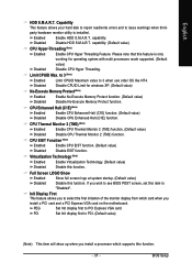
... CPU Hyper Threading Feature. CPU Enhanced Halt (C1E) (Note) Enabled Disabled Enable CPU Enhanced Halt (C1E) function. (Default value) Disable CPU Enhanced Halt (C1E) function. BIOS Setup Disable CPUID Limit for operating system with multi processors mode supported. (Default Disabled value) Disable CPU Hyper Threading. Capability This feature allows your hard... EIST function. Full Screen LOGO Show Enabled Disabled Show full screen logo at system startup. (Default value) Disable this function. If you wish to see BIOS POST screen, set this function. - 37 -
... CPU Hyper Threading Feature. CPU Enhanced Halt (C1E) (Note) Enabled Disabled Enable CPU Enhanced Halt (C1E) function. (Default value) Disable CPU Enhanced Halt (C1E) function. BIOS Setup Disable CPUID Limit for operating system with multi processors mode supported. (Default Disabled value) Disable CPU Hyper Threading. Capability This feature allows your hard... EIST function. Full Screen LOGO Show Enabled Disabled Show full screen logo at system startup. (Default value) Disable this function. If you wish to see BIOS POST screen, set this function. - 37 -
Manual
Page 38
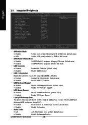
... function. (Default value) Disabled Disable Azalia audio function. USB 2.0 Controller Disable this function. Enabled BIOS will scan all USB storage devices. (Default value) Disabled Azalia Codec Disable this function if you are not using onboard USB 2.0 feature. GA-965P-DS3/S3 Motherboard - 38 - USB Controller Enabled Enable USB Controller. (Default value) Disabled Disable USB...
... function. (Default value) Disabled Disable Azalia audio function. USB 2.0 Controller Disable this function. Enabled BIOS will scan all USB storage devices. (Default value) Disabled Azalia Codec Disable this function if you are not using onboard USB 2.0 feature. GA-965P-DS3/S3 Motherboard - 38 - USB Controller Enabled Enable USB Controller. (Default value) Disabled Disable USB...
Manual
Page 39
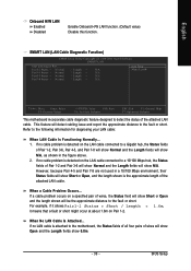
... Diagnostic Function) CMOS Setup Utility-Copyright (C) 1984-2006 Award Software SMART LAN Start detecting at about 1.6m on a specified pair of the attached LAN cable. BIOS Setup English Onboard H/W LAN Enabled Disabled Enable Onboard H/W LAN function. (Default value) Disable this function.
... Diagnostic Function) CMOS Setup Utility-Copyright (C) 1984-2006 Award Software SMART LAN Start detecting at about 1.6m on a specified pair of the attached LAN cable. BIOS Setup English Onboard H/W LAN Enabled Disabled Enable Onboard H/W LAN function. (Default value) Disable this function.
Manual
Page 40
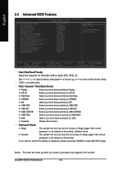
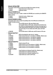
Onboard SATA/IDE Ctrl Mode This function allows users to AHCI mode. Onboard Serial Port 1 Auto BIOS will automatically setup the port 1 address. 3F8/IRQ4 Enable onboard Serial port 1 and address is 3F8/IRQ4. (Default value) 2F8/IRQ3 Enable onboard Serial ... value) Enable this function. Onboard SATA/IDE Device This function allows users to invoke the boot ROM of the SATA ports controlled by the GIGABYTE SATA2 controller. Enable onboard Serial port 1 and address is an interface specification that allows the storage driver to IDE mode. GA-965P-DS3/S3 Motherboard - 40 -
Onboard SATA/IDE Ctrl Mode This function allows users to AHCI mode. Onboard Serial Port 1 Auto BIOS will automatically setup the port 1 address. 3F8/IRQ4 Enable onboard Serial port 1 and address is 3F8/IRQ4. (Default value) 2F8/IRQ3 Enable onboard Serial ... value) Enable this function. Onboard SATA/IDE Device This function allows users to invoke the boot ROM of the SATA ports controlled by the GIGABYTE SATA2 controller. Enable onboard Serial port 1 and address is an interface specification that allows the storage driver to IDE mode. GA-965P-DS3/S3 Motherboard - 40 -


