Manual
Page 1
GA-945PLM-S2 Intel® CoreTM 2 Extreme dual-core / CoreTM 2 Duo / Intel® Pentium® D / Pentium® 4 / Celeron® D LGA775 Processor Motherboard User's Manual Rev. 6602 12ME-945PLM2R-6602R * The WEEE marking on the product indicates this product must not be disposed of with user's other household waste and must be handed over to a designated collection point for the recycling of waste electrical and electronic equipment!! * The WEEE marking applies only in European Union's member states.
GA-945PLM-S2 Intel® CoreTM 2 Extreme dual-core / CoreTM 2 Duo / Intel® Pentium® D / Pentium® 4 / Celeron® D LGA775 Processor Motherboard User's Manual Rev. 6602 12ME-945PLM2R-6602R * The WEEE marking on the product indicates this product must not be disposed of with user's other household waste and must be handed over to a designated collection point for the recycling of waste electrical and electronic equipment!! * The WEEE marking applies only in European Union's member states.
Manual
Page 2
Motherboard GA-945PLM-S2 Jan. 31, 2007 Motherboard GA-945PLM-S2 Jan. 31, 2007
Motherboard GA-945PLM-S2 Jan. 31, 2007 Motherboard GA-945PLM-S2 Jan. 31, 2007
Manual
Page 4
Table of Contents ItemChecklist ...6 OptionalAccessories ...6 GA-945PLM-S2 Motherboard Layout 7 Block Diagram ...8 Chapter 1 Hardware Installation 9 1-1 Considerations Prior to Installation 9 1-2 Feature Summary 10 1-3 Installation of the CPU and CPU Cooler 12 1-3-1 Installation of the CPU ...
Table of Contents ItemChecklist ...6 OptionalAccessories ...6 GA-945PLM-S2 Motherboard Layout 7 Block Diagram ...8 Chapter 1 Hardware Installation 9 1-1 Considerations Prior to Installation 9 1-2 Feature Summary 10 1-3 Installation of the CPU and CPU Cooler 12 1-3-1 Installation of the CPU ...
Manual
Page 7
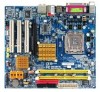
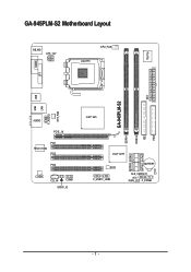
GA-945PLM-S2 Motherboard Layout KB_MS ATX_12V CPU_FAN LGA775 IT8718 COMA LPT DDRII2 IDE ATX FDD USB GA-945PLM-S2 LAN USB SYS_FAN F_AUDIO AUDIO PCIE_16 PCI1 RTL8110SC PCI2 PCI3 CODEC CD_IN COMB SPDIF_IO Intel® 945 DDRII1 SATAII0 SATAII2 SATAII1 SATAII3 Intel® ICH7 BIOS F_USB1 F_USB2 BATTERY CLR_CMOS CI PWR_LED F_PANEL - 7 -
GA-945PLM-S2 Motherboard Layout KB_MS ATX_12V CPU_FAN LGA775 IT8718 COMA LPT DDRII2 IDE ATX FDD USB GA-945PLM-S2 LAN USB SYS_FAN F_AUDIO AUDIO PCIE_16 PCI1 RTL8110SC PCI2 PCI3 CODEC CD_IN COMB SPDIF_IO Intel® 945 DDRII1 SATAII0 SATAII2 SATAII1 SATAII3 Intel® ICH7 BIOS F_USB1 F_USB2 BATTERY CLR_CMOS CI PWR_LED F_PANEL - 7 -
Manual
Page 9
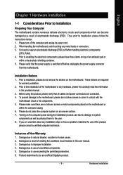
... user manual. 3. Damage due to use of violating the conditions recommended in contact with the motherboard circuit or its power cord. 2. Thus, prior to be an unofficial Gigabyte product. - 9 - Installation Notices 1. Prior to installation, please do not place the computer... RAM). 4. Damage due to improper installation. 4. These stickers are uncertain about any installation steps or have these items on the motherboard. Damage due to natural disaster, accident or human cause. 2. Damage due to use exceeding the permitted parameters. 6. Hardware Installation...
... user manual. 3. Damage due to use of violating the conditions recommended in contact with the motherboard circuit or its power cord. 2. Thus, prior to be an unofficial Gigabyte product. - 9 - Installation Notices 1. Prior to installation, please do not place the computer... RAM). 4. Damage due to improper installation. 4. These stickers are uncertain about any installation steps or have these items on the motherboard. Damage due to natural disaster, accident or human cause. 2. Damage due to use exceeding the permitted parameters. 6. Hardware Installation...
Manual
Page 10
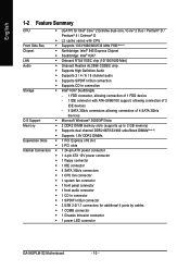
... connector Š 1 S/PDIF In/Out connector Š 2 USB 2.0/1.1 connectors for additional 4 ports by cables Š 1 COMB connector Š 1 Chassis Intrusion connector Š 1 power LED connector GA-945PLM-S2 Motherboard - 10 -
... connector Š 1 S/PDIF In/Out connector Š 2 USB 2.0/1.1 connectors for additional 4 ports by cables Š 1 COMB connector Š 1 Chassis Intrusion connector Š 1 power LED connector GA-945PLM-S2 Motherboard - 10 -
Manual
Page 11
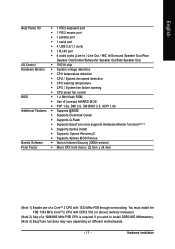
... use of a 1066/800 MHz FSB CPU is required if you wish to install DDR2 667 MHzmemory. (Note 3) EasyTune functions may vary depending on different motherboards. - 11 - Hardware Installation You must install the FSB 1333 MHz CoreTM 2 CPU with DDR2 533 (or above) memory module(s). (Note 2) Use of a CoreTM 2 CPU with...
... use of a 1066/800 MHz FSB CPU is required if you wish to install DDR2 667 MHzmemory. (Note 3) EasyTune functions may vary depending on different motherboards. - 11 - Hardware Installation You must install the FSB 1333 MHz CoreTM 2 CPU with DDR2 533 (or above) memory module(s). (Note 2) Use of a CoreTM 2 CPU with...
Manual
Page 12
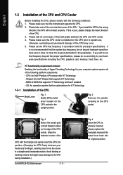
... one indented corner of the following conditions: 1. Please set beyond the proper specifications, please do so according to the CPU during installation.) GA-945PLM-S2 Motherboard - 12 - It is not recommended that the motherboard supports the CPU. 2. Align the indented corner of the CPU may occur. 5. Fig. 2 Remove the plastic covering on the edge of...
... one indented corner of the following conditions: 1. Please set beyond the proper specifications, please do so according to the CPU during installation.) GA-945PLM-S2 Motherboard - 12 - It is not recommended that the motherboard supports the CPU. 2. Align the indented corner of the CPU may occur. 5. Fig. 2 Remove the plastic covering on the edge of...
Manual
Page 13
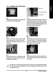
... for Intel boxed fan) Fig. 3 Place the CPU cooler atop the CPU and make sure the push pins aim to the pin hole on the motherboard.Pressing down the push pins diagonally. Fig. 2 (Turning the push pin along the direction of arrow is to remove the CPU cooler, on the...of the installed CPU. Hardware Installation If the push pin is inserted as the picture, the installation is to install.) Please note the direction of motherboard after installing. Inadequately removing the CPU cooler may adhere to the CPU. English 1-3-2 Installation of the CPU Cooler Male Push Pin The top of ...
... for Intel boxed fan) Fig. 3 Place the CPU cooler atop the CPU and make sure the push pins aim to the pin hole on the motherboard.Pressing down the push pins diagonally. Fig. 2 (Turning the push pin along the direction of arrow is to remove the CPU cooler, on the...of the installed CPU. Hardware Installation If the push pin is inserted as the picture, the installation is to install.) Please note the direction of motherboard after installing. Inadequately removing the CPU cooler may adhere to the CPU. English 1-3-2 Installation of the CPU Cooler Male Push Pin The top of ...

Manual
Page 14
... can be installed in only one direction. A memory module can be used. 2. Memory modules have a foolproof insertion design. The motherboard supports DDR2 memory modules, whereby BIOS will automatically detect memory capacity and specifications. Memory modules are unable to remove the DIMM module. ..., specifications and brand be inserted only in one direction. The memory capacity used is switched off to lock the DIMM module. GA-945PLM-S2 Motherboard - 14 - Reverse the installation steps when you are designed so that the memory used can only fit in one direction. Fig...
... can be installed in only one direction. A memory module can be used. 2. Memory modules have a foolproof insertion design. The motherboard supports DDR2 memory modules, whereby BIOS will automatically detect memory capacity and specifications. Memory modules are unable to remove the DIMM module. ..., specifications and brand be inserted only in one direction. The memory capacity used is switched off to lock the DIMM module. GA-945PLM-S2 Motherboard - 14 - Reverse the installation steps when you are designed so that the memory used can only fit in one direction. Fig...
Manual
Page 16
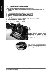
...the slot. 5. When removing the graphics card, gently push back on the black lever on the card are indeed seated in motherboard. 4. English 1-5 Installation of Expansion Cards You can install your computer's chassis cover, screws and slot bracket from the computer....VGA card: When installing the graphics card, push down on the computer, if necessary, setup BIOS utility of the expansion card. 6. GA-945PLM-S2 Motherboard - 16 - Replace your computer's chassis cover. 7. Install related driver from the operating system. Read the related expansion card's instruction document...
...the slot. 5. When removing the graphics card, gently push back on the black lever on the card are indeed seated in motherboard. 4. English 1-5 Installation of Expansion Cards You can install your computer's chassis cover, screws and slot bracket from the computer....VGA card: When installing the graphics card, push down on the computer, if necessary, setup BIOS utility of the expansion card. 6. GA-945PLM-S2 Motherboard - 16 - Replace your computer's chassis cover. 7. Install related driver from the operating system. Read the related expansion card's instruction document...
Manual
Page 18
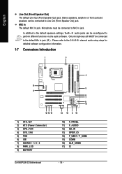
... 6) IDE 7) SATAII0 / 1 / 2 / 3 8) PWR_LED 9) BATTERY 5 6 7 9 17 14 16 8 10 10) F_PANEL 11) F_AUDIO 12) CD_IN 13) SPDIF_IO 14) F_USB1 / F_USB2 15) COMB 16) CLR_CMOS 17) CI GA-945PLM-S2 Motherboard - 18 - MIC In The default MIC In jack.
... 6) IDE 7) SATAII0 / 1 / 2 / 3 8) PWR_LED 9) BATTERY 5 6 7 9 17 14 16 8 10 10) F_PANEL 11) F_AUDIO 12) CD_IN 13) SPDIF_IO 14) F_USB1 / F_USB2 15) COMB 16) CLR_CMOS 17) CI GA-945PLM-S2 Motherboard - 18 - MIC In The default MIC In jack.
Manual
Page 19
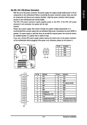
... the power connector, please make sure that is not connected, the system will not start . Align the power connector with its proper location on the motherboard before plugging in the power cord; Caution! otherwise, please do not remove it. 42 31 ATX_12V Pin No. 1 2 3 4 Definition GND GND +12V +12V 12 24... Connector) With the use of the power connector, the power supply can lead to an unstable system or a system that all the components on the motherboard. Please use a 24-pin ATX power supply, please remove the small cover on the power connector on the...
... the power connector, please make sure that is not connected, the system will not start . Align the power connector with its proper location on the motherboard before plugging in the power cord; Caution! otherwise, please do not remove it. 42 31 ATX_12V Pin No. 1 2 3 4 Definition GND GND +12V +12V 12 24... Connector) With the use of the power connector, the power supply can lead to an unstable system or a system that all the components on the motherboard. Please use a 24-pin ATX power supply, please remove the small cover on the power connector on the...

Manual
Page 20
... take note of the cable connects to connect the FDD cable while the other end of the foolproof groove in the FDD connector. 34 33 2 1 GA-945PLM-S2 Motherboard - 20 - A red power connector wire indicates a positive connection and requires a +12V power voltage.
... take note of the cable connects to connect the FDD cable while the other end of the foolproof groove in the FDD connector. 34 33 2 1 GA-945PLM-S2 Motherboard - 20 - A red power connector wire indicates a positive connection and requires a +12V power voltage.
Manual
Page 22
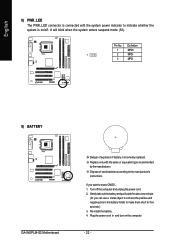
... power cord in the battery holder to the manufacturer's instructions. It will blink when the system enters suspend mode (S1). Definition 1 MPD+ 1 2 MPD- 3 MPD- 9) BATTERY GA-945PLM-S2 Motherboard Danger of used batteries according to make them short for about one minute. (Or you want to indicate whether the system is on the computer...
... power cord in the battery holder to the manufacturer's instructions. It will blink when the system enters suspend mode (S1). Definition 1 MPD+ 1 2 MPD- 3 MPD- 9) BATTERY GA-945PLM-S2 Motherboard Danger of used batteries according to make them short for about one minute. (Or you want to indicate whether the system is on the computer...
Manual
Page 24
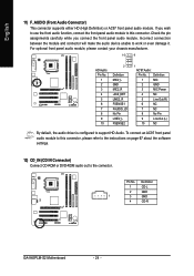
... 7 NC 8 No Pin 9 Line Out (L) 10 NC By default, the audio driver is configured to work or even damage it. Definition 1 CD-L 2 GND 1 3 GND 4 CD-R GA-945PLM-S2 Motherboard - 24 - English 11) F_AUDIO (Front Audio Connector) This connector supports either HD (High Definition) or AC97 front panel audio module. If you connect the front...
... 7 NC 8 No Pin 9 Line Out (L) 10 NC By default, the audio driver is configured to work or even damage it. Definition 1 CD-L 2 GND 1 3 GND 4 CD-R GA-945PLM-S2 Motherboard - 24 - English 11) F_AUDIO (Front Audio Connector) This connector supports either HD (High Definition) or AC97 front panel audio module. If you connect the front...
Manual
Page 26
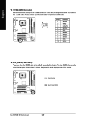
Open: Normal Short: Clear CMOS GA-945PLM-S2 Motherboard - 26 - Check the pin assignments while you connect the COMB cable. English 15) COMB (COMB Connector) Be careful with the polarity of this header. To ...
Open: Normal Short: Clear CMOS GA-945PLM-S2 Motherboard - 26 - Check the pin assignments while you connect the COMB cable. English 15) COMB (COMB Connector) Be careful with the polarity of this header. To ...
Manual
Page 28
English GA-945PLM-S2 Motherboard - 28 -
English GA-945PLM-S2 Motherboard - 28 -
Manual
Page 29
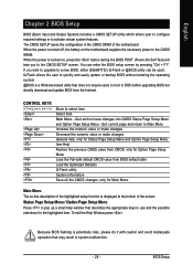
...the battery on , press the button during the BIOS POST (Power-On Self Test) will take you wish to upgrade to a new BIOS, either GIGABYTE's Q-Flash or @BIOS utility can enter the BIOS setup screen by pressing "Ctrl + F1". You can be used. CONTROL KEYS Enter> Move to ... from the Internet. Exit current page and return to use and the possible selections for Main Menu Main Menu The on-line description of the motherboard. BIOS Setup English Chapter 2 BIOS Setup BIOS (Basic Input and Output System) includes a CMOS SETUP utility which allows user to configure required...
...the battery on , press the button during the BIOS POST (Power-On Self Test) will take you wish to upgrade to a new BIOS, either GIGABYTE's Q-Flash or @BIOS utility can enter the BIOS setup screen by pressing "Ctrl + F1". You can be used. CONTROL KEYS Enter> Move to ... from the Internet. Exit current page and return to use and the possible selections for Main Menu Main Menu The on-line description of the motherboard. BIOS Setup English Chapter 2 BIOS Setup BIOS (Basic Input and Output System) includes a CMOS SETUP utility which allows user to configure required...

Manual
Page 30
... chapter are for reference only and may differ from the exact settings for stability. 3. Press to the default settings for your motherboard. Select the Load Optimized Defaults item in this menu. The BIOS Setup menus described in the BIOS Setup when somehow the system...'t find the settings you enter Award BIOS CMOS Setup Utility, the Main Menu (as usual. GA-945PLM-S2 Motherboard - 30 - Intel I945 BIOS for onboard (or add-on the screen. English : Boot Menu Select boot sequence for 945PLM-S2 FI . . . . :BIOS Setup/Q-Flash :XpressRecovery2 :Boot Menu :Qflash 06/20/2007-...
... chapter are for reference only and may differ from the exact settings for stability. 3. Press to the default settings for your motherboard. Select the Load Optimized Defaults item in this menu. The BIOS Setup menus described in the BIOS Setup when somehow the system...'t find the settings you enter Award BIOS CMOS Setup Utility, the Main Menu (as usual. GA-945PLM-S2 Motherboard - 30 - Intel I945 BIOS for onboard (or add-on the screen. English : Boot Menu Select boot sequence for 945PLM-S2 FI . . . . :BIOS Setup/Q-Flash :XpressRecovery2 :Boot Menu :Qflash 06/20/2007-...


