Manual
Page 1
GA-945PL-DS3/ GA-945PL-S3 (rev. 2.0) Intel® CoreTM 2 Extreme dual-core / CoreTM 2 Duo / Intel® Pentium® D / Pentium® 4 / Celeron® D LGA775 Processor Motherboard User's Manual Rev. 2002 12ME-945PLDS3-2002R * The WEEE marking on the product indicates this product must not be disposed of with user's other household waste and must be handed over to a designated collection point for the recycling of waste electrical and electronic equipment!! * The WEEE marking applies only in European Union's member states.
GA-945PL-DS3/ GA-945PL-S3 (rev. 2.0) Intel® CoreTM 2 Extreme dual-core / CoreTM 2 Duo / Intel® Pentium® D / Pentium® 4 / Celeron® D LGA775 Processor Motherboard User's Manual Rev. 2002 12ME-945PLDS3-2002R * The WEEE marking on the product indicates this product must not be disposed of with user's other household waste and must be handed over to a designated collection point for the recycling of waste electrical and electronic equipment!! * The WEEE marking applies only in European Union's member states.
Manual
Page 2
Motherboard GA-945PL-DS3/GA-945PL-S3 (rev. 2.0) Oct. 25, 2006 Motherboard GA-945PL-DS3/ GA-945PL-S3 (rev. 2.0) Oct. 25, 2006
Motherboard GA-945PL-DS3/GA-945PL-S3 (rev. 2.0) Oct. 25, 2006 Motherboard GA-945PL-DS3/ GA-945PL-S3 (rev. 2.0) Oct. 25, 2006
Manual
Page 4
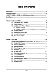
Table of Contents ItemChecklist ...6 OptionalAccessories ...6 GA-945PL-DS3/GA-945PL-S3 (rev. 2.0) Motherboard Layout 7 Block Diagram ...8 Chapter 1 Hardware Installation 9 1-1 Considerations Prior to Installation 9 1-2 Feature Summary 10 1-3 Installation ... Installation of Expansion Cards 16 1-6 I/O Back Panel Introduction 17 1-7 Connectors Introduction 18 Chapter 2 BIOS Setup 29 The Main Menu (For example: GA-945PL-DS3 BIOS Ver.: F1a 30 2-1 Standard CMOS Features 32 2-2 Advanced BIOS Features 34 2-3 IntegratedPeripherals 36 2-4 Power Management Setup 39 2-5 PnP/PCI Configurations ...
Table of Contents ItemChecklist ...6 OptionalAccessories ...6 GA-945PL-DS3/GA-945PL-S3 (rev. 2.0) Motherboard Layout 7 Block Diagram ...8 Chapter 1 Hardware Installation 9 1-1 Considerations Prior to Installation 9 1-2 Feature Summary 10 1-3 Installation ... Installation of Expansion Cards 16 1-6 I/O Back Panel Introduction 17 1-7 Connectors Introduction 18 Chapter 2 BIOS Setup 29 The Main Menu (For example: GA-945PL-DS3 BIOS Ver.: F1a 30 2-1 Standard CMOS Features 32 2-2 Advanced BIOS Features 34 2-3 IntegratedPeripherals 36 2-4 Power Management Setup 39 2-5 PnP/PCI Configurations ...
Manual
Page 7
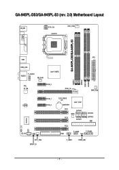
GA-945PL-DS3/GA-945PL-S3 (rev. 2.0) Motherboard Layout KB_MS ATX_12V LGA775 CPU_FAN GA-945PL-DS3/GA-945PL-S3 COMA LPT ATX USB USB_LAN F_AUDIO AUDIO NB_FAN Intel® 945PL RTL 8111B PCIE_3 PCIE_16 DDRII1 DDRII2 DDRII3 DDRII4 PWR_FAN CODEC PCIE_1 PCIE_2 CI CD_IN SYS _FAN SPDIF_IO CLR_CMOS BATTERY Intel® ICH7 PCI1 SATAII0 BIOS PCI2 SATAII1 PCI3 FDD F_USB2 SATAII2 SATAII3 IDE1 F_PANEL F_USB1 PWR_LED - 7 - REV: 2.0 IT8718
GA-945PL-DS3/GA-945PL-S3 (rev. 2.0) Motherboard Layout KB_MS ATX_12V LGA775 CPU_FAN GA-945PL-DS3/GA-945PL-S3 COMA LPT ATX USB USB_LAN F_AUDIO AUDIO NB_FAN Intel® 945PL RTL 8111B PCIE_3 PCIE_16 DDRII1 DDRII2 DDRII3 DDRII4 PWR_FAN CODEC PCIE_1 PCIE_2 CI CD_IN SYS _FAN SPDIF_IO CLR_CMOS BATTERY Intel® ICH7 PCI1 SATAII0 BIOS PCI2 SATAII1 PCI3 FDD F_USB2 SATAII2 SATAII3 IDE1 F_PANEL F_USB1 PWR_LED - 7 - REV: 2.0 IT8718
Manual
Page 10
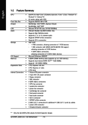
...Pentium® 4 / Celeron® D Š L2 cache varies with CPU Front Side Bus Š Supports 800/533 MHz FSB Chipset Northbridge: Intel® 945PL Express Chipset Š Southbridge: Intel® ICH7 LAN Š Onboard RTL8111B chip (10/100/1000Mbit) Audio Š Onboard Realtek ALC888 CODEC chip Š Supports .../Out connector Š 2 USB 2.0/1.1 connectors for additional 4 USB 2.0/1.1 ports by cables Š 1 power LED connector Š 1 Chassis Intrusion connector "*" Only the GA-945PL-DS3 adopts All-Solid Capacitor design. GA-945PL-(D)S3 (rev. 2.0) Motherboard - 10 -
...Pentium® 4 / Celeron® D Š L2 cache varies with CPU Front Side Bus Š Supports 800/533 MHz FSB Chipset Northbridge: Intel® 945PL Express Chipset Š Southbridge: Intel® ICH7 LAN Š Onboard RTL8111B chip (10/100/1000Mbit) Audio Š Onboard Realtek ALC888 CODEC chip Š Supports .../Out connector Š 2 USB 2.0/1.1 connectors for additional 4 USB 2.0/1.1 ports by cables Š 1 power LED connector Š 1 Chassis Intrusion connector "*" Only the GA-945PL-DS3 adopts All-Solid Capacitor design. GA-945PL-(D)S3 (rev. 2.0) Motherboard - 10 -
Manual
Page 12
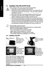
... - If you install the CPU in accordance with the processor specifications. Fig. 2 Remove the plastic covering on the CPU prior to the CPU during installation.) GA-945PL-(D)S3 (rev. 2.0) Motherboard - 12 - English 1-3 Installation of the CPU and CPU Cooler Before installing the CPU, please comply with the following platform components: - It is properly...
... - If you install the CPU in accordance with the processor specifications. Fig. 2 Remove the plastic covering on the CPU prior to the CPU during installation.) GA-945PL-(D)S3 (rev. 2.0) Motherboard - 12 - English 1-3 Installation of the CPU and CPU Cooler Before installing the CPU, please comply with the following platform components: - It is properly...
Manual
Page 14
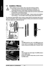
... used is supported by the motherboard. Notch DDRII Fig.1 The DIMM socket has a notch, so the DIMM memory module can differ with the following conditions: 1. GA-945PL-(D)S3 (rev. 2.0) Motherboard - 14 - Before installing or removing memory modules, please make sure that memory of similar capacity, specifications and brand be inserted only in one...
... used is supported by the motherboard. Notch DDRII Fig.1 The DIMM socket has a notch, so the DIMM memory module can differ with the following conditions: 1. GA-945PL-(D)S3 (rev. 2.0) Motherboard - 14 - Before installing or removing memory modules, please make sure that memory of similar capacity, specifications and brand be inserted only in one...
Manual
Page 15
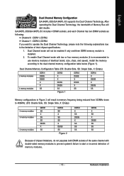
...will not be enabled if only one/three DDRII memory module is recommended to use memory modules of memory modules, - 15 - Hardware Installation GA-945PL-DS3/GA-945PL-S3 includes 4 DIMM sockets, and each Channel has two DIMM sockets as following: Channel 0 : DDRII1, DDRII2 Channel 1 : DDRII3, DDRII4 ... explanations due to the dual channel memory configuration table below (Figure 1). English Dual Channel Memory Configuration GA-945PL-DS3/GA-945PL-S3 supports the Dual Channel Technology. After operating the Dual Channel Technology, the bandwidth of Intel chipset specifications. 1.
...will not be enabled if only one/three DDRII memory module is recommended to use memory modules of memory modules, - 15 - Hardware Installation GA-945PL-DS3/GA-945PL-S3 includes 4 DIMM sockets, and each Channel has two DIMM sockets as following: Channel 0 : DDRII1, DDRII2 Channel 1 : DDRII3, DDRII4 ... explanations due to the dual channel memory configuration table below (Figure 1). English Dual Channel Memory Configuration GA-945PL-DS3/GA-945PL-S3 supports the Dual Channel Technology. After operating the Dual Channel Technology, the bandwidth of Intel chipset specifications. 1.
Manual
Page 16
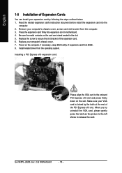
... expansion card into expansion slot in the slot. 5. Make sure your expansion card by the latch at the end of the PCI Express x16 slot. GA-945PL-(D)S3 (rev. 2.0) Motherboard - 16 - Replace the screw to release the card. When you try uninstall the VGA card, please gently press the latch as the picture...
... expansion card into expansion slot in the slot. 5. Make sure your expansion card by the latch at the end of the PCI Express x16 slot. GA-945PL-(D)S3 (rev. 2.0) Motherboard - 16 - Replace the screw to release the card. When you try uninstall the VGA card, please gently press the latch as the picture...
Manual
Page 18
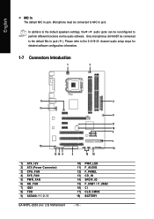
... software configuration information. 1-7 Connectors Introduction 1 3 6 2 11 5 17 18 9 7 16 12 13 14 4 8 15 10 1) ATX_12V 2) ATX (Power Connector) 3) CPU_FAN 4) SYS_FAN 5) PWR_FAN 6) NB_FAN 7) IDE1 8) FDD 9) SATAII0 / 1 / 2 / 3 GA-945PL-(D)S3 (rev. 2.0) Motherboard 10) PWR_LED 11) F_AUDIO 12) F_PANEL 13) CD_IN 14) SPDIF_IO 15) F_USB1 / F_USB2 16) CI 17) CLR_CMOS 18) BATTERY - 18 - In addition to...
... software configuration information. 1-7 Connectors Introduction 1 3 6 2 11 5 17 18 9 7 16 12 13 14 4 8 15 10 1) ATX_12V 2) ATX (Power Connector) 3) CPU_FAN 4) SYS_FAN 5) PWR_FAN 6) NB_FAN 7) IDE1 8) FDD 9) SATAII0 / 1 / 2 / 3 GA-945PL-(D)S3 (rev. 2.0) Motherboard 10) PWR_LED 11) F_AUDIO 12) F_PANEL 13) CD_IN 14) SPDIF_IO 15) F_USB1 / F_USB2 16) CI 17) CLR_CMOS 18) BATTERY - 18 - In addition to...
Manual
Page 20
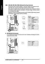
... cooler fan power connector supplies a +12V power voltage via a 3-pin/4-pin (only for CPU_FAN) power connector and possesses a foolproof connection design. Definition 1 1 GND 2 +12V 3 NC GA-945PL-(D)S3 (rev. 2.0) Motherboard - 20 - Most coolers are designed with color-coded power connector wires. A red power connector wire indicates a positive connection and requires a +12V power voltage...
... cooler fan power connector supplies a +12V power voltage via a 3-pin/4-pin (only for CPU_FAN) power connector and possesses a foolproof connection design. Definition 1 1 GND 2 +12V 3 NC GA-945PL-(D)S3 (rev. 2.0) Motherboard - 20 - Most coolers are designed with color-coded power connector wires. A red power connector wire indicates a positive connection and requires a +12V power voltage...
Manual
Page 22
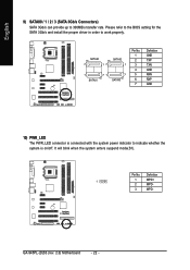
... 1 1 71 7 SATAII1 SATAII3 Pin No. 1 2 3 4 5 6 7 Definition GND TXP TXN GND RXN RXP GND 10) PWR_LED The PWR_LED connector is on/off. Definition 1 1 MPD+ 2 MPD- 3 MPD- GA-945PL-(D)S3 (rev. 2.0) Motherboard - 22 - It will blink when the system enters suspend mode(S1). Please refer to the BIOS setting for the SATA 3Gb/s and install...
... 1 1 71 7 SATAII1 SATAII3 Pin No. 1 2 3 4 5 6 7 Definition GND TXP TXN GND RXN RXP GND 10) PWR_LED The PWR_LED connector is on/off. Definition 1 1 MPD+ 2 MPD- 3 MPD- GA-945PL-(D)S3 (rev. 2.0) Motherboard - 22 - It will blink when the system enters suspend mode(S1). Please refer to the BIOS setting for the SATA 3Gb/s and install...
Manual
Page 24
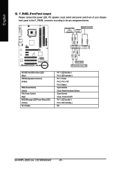
... HD+ HD- Pin 3: NC Pin 4: Data(-) Open: Normal Close: Reset Hardware System Open: Normal Close: Power On/Off Pin 1: LED anode(+) Pin 2: LED cathode(-) NC GA-945PL-(D)S3 (rev. 2.0) Motherboard - 24 - English 12) F_PANEL (Front Panel Jumper) Please connect the power LED, PC speaker, reset switch and power switch etc of your chassis...
... HD+ HD- Pin 3: NC Pin 4: Data(-) Open: Normal Close: Reset Hardware System Open: Normal Close: Power On/Off Pin 1: LED anode(+) Pin 2: LED cathode(-) NC GA-945PL-(D)S3 (rev. 2.0) Motherboard - 24 - English 12) F_PANEL (Front Panel Jumper) Please connect the power LED, PC speaker, reset switch and power switch etc of your chassis...
Manual
Page 26
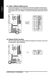
English 15) F_USB1 / F_USB2 (Front USB Connectors) Be careful with the polarity of the front USB connector. Pin No. Definition 1 1 Signal 2 GND GA-945PL-(D)S3 (rev. 2.0) Motherboard - 26 - For optional front USB cable, please contact your local dealer. 2 10 1 9 Pin No. 1 2 3 4 5 6 7 8 9 10 Definition Power (5V) Power (5V) USB DXUSB DyUSB ...
English 15) F_USB1 / F_USB2 (Front USB Connectors) Be careful with the polarity of the front USB connector. Pin No. Definition 1 1 Signal 2 GND GA-945PL-(D)S3 (rev. 2.0) Motherboard - 26 - For optional front USB cable, please contact your local dealer. 2 10 1 9 Pin No. 1 2 3 4 5 6 7 8 9 10 Definition Power (5V) Power (5V) USB DXUSB DyUSB ...
Manual
Page 28
English GA-945PL-(D)S3 (rev. 2.0) Motherboard - 28 -
English GA-945PL-(D)S3 (rev. 2.0) Motherboard - 28 -

Manual
Page 30
Startup Screen: (For example: GA-945PL-DS3 BIOS Ver.: F1a) English :POST Screen :BIOS Setup/Q-Flash :XpressRecovery2 :Boot Menu : POST Screen Press the TAB key to see BIOS POST screen. (To show ... Load Optimized Defaults item in this chapter are for reference only and may differ from the exact settings for stability. 3. The Main Menu (For example: GA-945PL-DS3 BIOS Ver.: F1a) Once you want, press "Ctrl+F1" to select the first boot device. This action makes the system reset to accept or enter...
Startup Screen: (For example: GA-945PL-DS3 BIOS Ver.: F1a) English :POST Screen :BIOS Setup/Q-Flash :XpressRecovery2 :Boot Menu : POST Screen Press the TAB key to see BIOS POST screen. (To show ... Load Optimized Defaults item in this chapter are for reference only and may differ from the exact settings for stability. 3. The Main Menu (For example: GA-945PL-DS3 BIOS Ver.: F1a) Once you want, press "Ctrl+F1" to select the first boot device. This action makes the system reset to accept or enter...

Manual
Page 32
... for faster system start up . The four options are used and the system will skip the automatic detection step and allow for automatic device detection. GA-945PL-(D)S3 (rev. 2.0) Motherboard - 32 - is , , , . The time is display-only Month Day The month, Jan. You can manually input the correct settings Access Mode Use this...
... for faster system start up . The four options are used and the system will skip the automatic detection step and allow for automatic device detection. GA-945PL-(D)S3 (rev. 2.0) Motherboard - 32 - is , , , . The time is display-only Month Day The month, Jan. You can manually input the correct settings Access Mode Use this...
Manual
Page 34
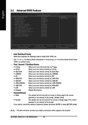
... the correct password is not entered at the prompt. LS120 Select your boot device priority by LS120. ZIP Select your boot device priority by ZIP. GA-945PL-(D)S3 (rev. 2.0) Motherboard - 34 - Hard Disk Select your boot device priority by Hard Disk. to Setup page if the correct password is not entered at the...
... the correct password is not entered at the prompt. LS120 Select your boot device priority by LS120. ZIP Select your boot device priority by ZIP. GA-945PL-(D)S3 (rev. 2.0) Motherboard - 34 - Hard Disk Select your boot device priority by Hard Disk. to Setup page if the correct password is not entered at the...
Manual
Page 36
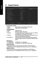
... PCI IDE On-Chip SATA Mode x PATA IDE Set to SATA Port 0/2 Set to SATA Port 1/3 Set to Ch. 1 Master/Slave. SATA Port 1/3 Set to ". GA-945PL-(D)S3 (rev. 2.0) Motherboard - 36 - PATA devices will auto make by the setting "On-Chip SATA Mode" and "PATA IDE Set to This value will be ignored...
... PCI IDE On-Chip SATA Mode x PATA IDE Set to SATA Port 0/2 Set to SATA Port 1/3 Set to Ch. 1 Master/Slave. SATA Port 1/3 Set to ". GA-945PL-(D)S3 (rev. 2.0) Motherboard - 36 - PATA devices will auto make by the setting "On-Chip SATA Mode" and "PATA IDE Set to This value will be ignored...
Manual
Page 38
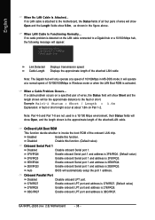
... the motherboard, the Status fields of all four pairs of wires will show Open, and the length shown is attached to the fault or short. GA-945PL-(D)S3 (rev. 2.0) Motherboard - 38 - Enabled Enable this function. (Default value) Onboard Serial Port 1 Disabled Disable onboard Serial port 1. 3F8/IRQ4 Enable onboard Serial port 1 and address...
... the motherboard, the Status fields of all four pairs of wires will show Open, and the length shown is attached to the fault or short. GA-945PL-(D)S3 (rev. 2.0) Motherboard - 38 - Enabled Enable this function. (Default value) Onboard Serial Port 1 Disabled Disable onboard Serial port 1. 3F8/IRQ4 Enable onboard Serial port 1 and address...

