Manual
Page 4
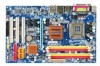
Table of Contents ItemChecklist ...6 OptionalAccessories ...6 GA-945PL-DS3/GA-945PL-S3 (rev. 2.0) Motherboard Layout 7 Block Diagram ...8 Chapter 1 Hardware Installation 9 1-1 Considerations Prior to Installation 9 1-2 Feature Summary 10 1-3 Installation of the CPU and CPU Cooler 12 1-3-1 Installation of the CPU 12 1-3-2 Installation of the Cooler 13 1-4 Installation of Memory 14 1-5 Installation of Expansion Cards 16 1-6 I/O Back Panel Introduction 17 1-7 Connectors Introduction...
Table of Contents ItemChecklist ...6 OptionalAccessories ...6 GA-945PL-DS3/GA-945PL-S3 (rev. 2.0) Motherboard Layout 7 Block Diagram ...8 Chapter 1 Hardware Installation 9 1-1 Considerations Prior to Installation 9 1-2 Feature Summary 10 1-3 Installation of the CPU and CPU Cooler 12 1-3-1 Installation of the CPU 12 1-3-2 Installation of the Cooler 13 1-4 Installation of Memory 14 1-5 Installation of Expansion Cards 16 1-6 I/O Back Panel Introduction 17 1-7 Connectors Introduction...

Manual
Page 8
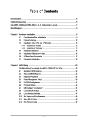
Block Diagram PCIe CLK (100 MHz) LGA775 Processor CPU CLK+/-(200/133 MHz) PCI Express x16 RJ45 RTL 8111B x1 PCI Express Bus x1 x1 x1 PCIe CLK (100 MHz) 3 PCI Express x1 PCI Bus Host Interface Intel® 945PL DDRII 400/533 MHz DIMM Dual Channel Memory MCH CLK(200/133 MHz) BIOS 4 SATA 3Gb/s Intel® ATA33/66/100 ICH7 IDE1 Channel Floppy IT8718 LPT Port COM Port CODEC 8 USB Ports PS/2 KB/Mouse Surround Speaker Out Center/Subwoofer Speaker Out Side Speaker Out MIC Line-Out Line-In SPDIF In SPDIF Out 3 PCI PCI CLK (33 MHz) - 8 -
Block Diagram PCIe CLK (100 MHz) LGA775 Processor CPU CLK+/-(200/133 MHz) PCI Express x16 RJ45 RTL 8111B x1 PCI Express Bus x1 x1 x1 PCIe CLK (100 MHz) 3 PCI Express x1 PCI Bus Host Interface Intel® 945PL DDRII 400/533 MHz DIMM Dual Channel Memory MCH CLK(200/133 MHz) BIOS 4 SATA 3Gb/s Intel® ATA33/66/100 ICH7 IDE1 Channel Floppy IT8718 LPT Port COM Port CODEC 8 USB Ports PS/2 KB/Mouse Surround Speaker Out Center/Subwoofer Speaker Out Side Speaker Out MIC Line-Out Line-In SPDIF In SPDIF Out 3 PCI PCI CLK (33 MHz) - 8 -
Manual
Page 9
... required for warranty validation. 2. Turning on the motherboard or within a electrostatic shielding container. 5. Damage due to be an unofficial Gigabyte product. - 9 - These stickers are uncertain about any installation steps or have these items on top of violating the conditions recommended... to the motherboard, please do not allow screws to wear an electrostatic discharge (ESD) cuff when handling electronic components (CPU, RAM). 4. Instances of Non-Warranty 1. Hardware Installation When handling the motherboard, avoid touching any hardware, please first carefully...
... required for warranty validation. 2. Turning on the motherboard or within a electrostatic shielding container. 5. Damage due to be an unofficial Gigabyte product. - 9 - These stickers are uncertain about any installation steps or have these items on top of violating the conditions recommended... to the motherboard, please do not allow screws to wear an electrostatic discharge (ESD) cuff when handling electronic components (CPU, RAM). 4. Instances of Non-Warranty 1. Hardware Installation When handling the motherboard, avoid touching any hardware, please first carefully...
Manual
Page 10
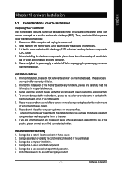
...CPU fan connector Š 1 system fan connector Š 1 power fan connector Š 1 northbridge fan connector Š 1 front panel connector Š 1 front audio connector Š 1 CD In connector Š 1 S/PDIF In/Out connector Š 2 USB 2.0/1.1 connectors for additional 4 USB 2.0/1.1 ports by cables Š 1 power LED connector Š 1 Chassis Intrusion connector "*" Only the GA-945PL-DS3... adopts All-Solid Capacitor design. GA-945PL-(D)S3 (rev. 2.0) Motherboard - 10 -
...CPU fan connector Š 1 system fan connector Š 1 power fan connector Š 1 northbridge fan connector Š 1 front panel connector Š 1 front audio connector Š 1 CD In connector Š 1 S/PDIF In/Out connector Š 2 USB 2.0/1.1 connectors for additional 4 USB 2.0/1.1 ports by cables Š 1 power LED connector Š 1 Chassis Intrusion connector "*" Only the GA-945PL-DS3... adopts All-Solid Capacitor design. GA-945PL-(D)S3 (rev. 2.0) Motherboard - 10 -
Manual
Page 11
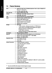
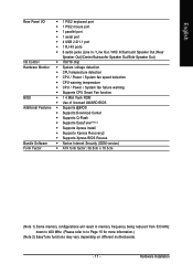
... Out/Side Speaker Out) I/O Control Š IT8718 chip Hardware Monitor Š System voltage detection Š CPU temperature detection Š CPU / Power / System fan speed detection Š CPU warning temperature Š CPU / Power / System fan failure warning Š Supports CPU Smart Fan function BIOS Š 1 4 Mbit flash ROM Š Use of licensed AWARD BIOS Additional Features...
... Out/Side Speaker Out) I/O Control Š IT8718 chip Hardware Monitor Š System voltage detection Š CPU temperature detection Š CPU / Power / System fan speed detection Š CPU warning temperature Š CPU / Power / System fan failure warning Š Supports CPU Smart Fan function BIOS Š 1 4 Mbit flash ROM Š Use of licensed AWARD BIOS Additional Features...
Manual
Page 12
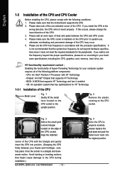
... recommended that supports HT Technology and has it into its original position. If you install the CPU in accordance with the processor specifications. Fig. 2 Remove the plastic covering on the CPU prior to the CPU during installation.) GA-945PL-(D)S3 (rev. 2.0) Motherboard - 12 - Please add an even layer of heat sink paste between your thumb...
... recommended that supports HT Technology and has it into its original position. If you install the CPU in accordance with the processor specifications. Fig. 2 Remove the plastic covering on the CPU prior to the CPU during installation.) GA-945PL-(D)S3 (rev. 2.0) Motherboard - 12 - Please add an even layer of heat sink paste between your thumb...
Manual
Page 13
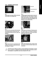
...the heat paste. Hardware Installation Fig. 2 (Turning the push pin along the direction of arrow is to remove the CPU cooler, on the contrary, is to install.) Please note the direction of the CPU cooler to the pin hole on the motherboard. Fig. 6 Finally, please attach the power connector of arrow sign... is complete. If the push pin is suggested that either thermal tape rather than heat paste be used for Intel boxed fan) Fig. 3 Place the CPU cooler atop the CPU and make sure the Male and Female push pin are joined closely. (for detailed installation instructions, please refer to the...
...the heat paste. Hardware Installation Fig. 2 (Turning the push pin along the direction of arrow is to remove the CPU cooler, on the contrary, is to install.) Please note the direction of the CPU cooler to the pin hole on the motherboard. Fig. 6 Finally, please attach the power connector of arrow sign... is complete. If the push pin is suggested that either thermal tape rather than heat paste be used for Intel boxed fan) Fig. 3 Place the CPU cooler atop the CPU and make sure the Male and Female push pin are joined closely. (for detailed installation instructions, please refer to the...
Manual
Page 19
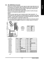
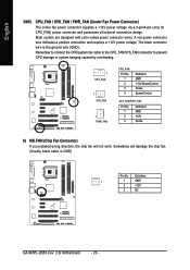
... power connector on the motherboard before plugging in the power cord ; If you use of the power connector, the power supply can lead to the CPU. Hardware Installation
... power connector on the motherboard before plugging in the power cord ; If you use of the power connector, the power supply can lead to the CPU. Hardware Installation
Manual
Page 20
... a 3-pin/4-pin (only for CPU_FAN) power connector and possesses a foolproof connection design. Definition 1 1 GND 2 +12V 3 NC GA-945PL-(D)S3 (rev. 2.0) Motherboard - 20 - Remember to connect the CPU/system fan cable to the CPU_FAN/SYS_FAN connector to prevent CPU damage or system hanging caused by overheating. 1 CPU_FAN 1 SYS_FAN 1 PWR_FAN CPU_FAN: Pin No. 1 2 3 4 Definition GND +12V...
... a 3-pin/4-pin (only for CPU_FAN) power connector and possesses a foolproof connection design. Definition 1 1 GND 2 +12V 3 NC GA-945PL-(D)S3 (rev. 2.0) Motherboard - 20 - Remember to connect the CPU/system fan cable to the CPU_FAN/SYS_FAN connector to prevent CPU damage or system hanging caused by overheating. 1 CPU_FAN 1 SYS_FAN 1 PWR_FAN CPU_FAN: Pin No. 1 2 3 4 Definition GND +12V...
Manual
Page 31
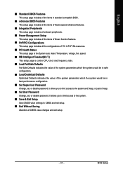
.... „ PC Health Status This setup page is the System auto detect Temperature, voltage, fan, speed. „ MB Intelligent Tweaker(M.I.T.) This setup page is control CPU clock and frequency ratio. „ Load Fail-Safe Defaults Fail-Safe Defaults indicates the value of the system parameters which the system would be in...
.... „ PC Health Status This setup page is the System auto detect Temperature, voltage, fan, speed. „ MB Intelligent Tweaker(M.I.T.) This setup page is control CPU clock and frequency ratio. „ Load Fail-Safe Defaults Fail-Safe Defaults indicates the value of the system parameters which the system would be in...
Manual
Page 33
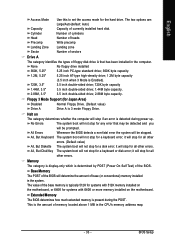
... The category is display-only which is present during power up. BIOS Setup Floppy 3 Mode Support (for any error that has been installed in the CPU's memory address map. - 33 - Cylinder Number of cylinders Head Precomp Number of heads Write precomp Landing Zone Sector Landing zone Number of sectors Drive A The...
... The category is display-only which is present during power up. BIOS Setup Floppy 3 Mode Support (for any error that has been installed in the CPU's memory address map. - 33 - Cylinder Number of cylinders Head Precomp Number of heads Write precomp Landing Zone Sector Landing zone Number of sectors Drive A The...
Manual
Page 34
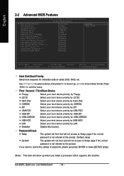
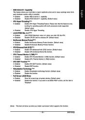
...boot device priority by USB-ZIP. Disabled Disable this function. Press to 3 (Note) No-Execute Memory Protect (Note) CPU Enhanced Halt (C1E) (Note) CPU Thermal Monitor 2(TM2) (Note) CPU EIST Function (Note) Virtualization Technology (Note) Full Screen LOGO Show [Press Enter] [Floppy] [Hard Disk] [CDROM...Disk Select your boot device priority by Hard Disk. Capability CPU Hyper-Threading (Note) Limit CPUID Max. First / Second / Third Boot Device Floppy Select your boot device priority by Floppy. to exit this menu. GA-945PL-(D)S3 (rev. 2.0) Motherboard - 34 - English 2-2 ...
...boot device priority by USB-ZIP. Disabled Disable this function. Press to 3 (Note) No-Execute Memory Protect (Note) CPU Enhanced Halt (C1E) (Note) CPU Thermal Monitor 2(TM2) (Note) CPU EIST Function (Note) Virtualization Technology (Note) Full Screen LOGO Show [Press Enter] [Floppy] [Hard Disk] [CDROM...Disk Select your boot device priority by Hard Disk. Capability CPU Hyper-Threading (Note) Limit CPUID Max. First / Second / Third Boot Device Floppy Select your boot device priority by Floppy. to exit this menu. GA-945PL-(D)S3 (rev. 2.0) Motherboard - 34 - English 2-2 ...
Manual
Page 35
... No-Execute Memory Protect function. (Default value) Disable No-Execute Memory Protect function. CPU Thermal Monitor 2 (TM2) (Note) Enabled Disabled Enable CPU Thermal Monitor 2 (TM2) function. (Default value) Disable CPU Thermal Monitor 2 (TM2) function. CPU EIST Function (Note) Enabled Disabled Enable CPU EIST function. (Default value) Disable EIST function. Virtualization Technology (Note) Enabled Enable Virtualization...
... No-Execute Memory Protect function. (Default value) Disable No-Execute Memory Protect function. CPU Thermal Monitor 2 (TM2) (Note) Enabled Disabled Enable CPU Thermal Monitor 2 (TM2) function. (Default value) Disable CPU Thermal Monitor 2 (TM2) function. CPU EIST Function (Note) Enabled Disabled Enable CPU EIST function. (Default value) Disable EIST function. Virtualization Technology (Note) Enabled Enable Virtualization...
Manual
Page 42
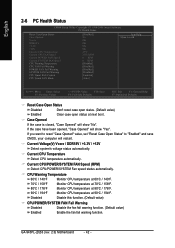
... 60oC / 140oF. 70oC / 158oF 80oC / 176oF 90oC / 194oF Disabled Monitor CPU temperature at next boot. Disable this function. (Default value) CPU/POWER/SYSTEM FAN Fail Warning Disabled Enabled Disable the fan fail warning function. (Default value) Enable the fan fail warning function. GA-945PL-(D)S3 (rev. 2.0) Motherboard - 42 - If you want to reset "Case...
... 60oC / 140oF. 70oC / 158oF 80oC / 176oF 90oC / 194oF Disabled Monitor CPU temperature at next boot. Disable this function. (Default value) CPU/POWER/SYSTEM FAN Fail Warning Disabled Enabled Disable the fan fail warning function. (Default value) Enable the fan fail warning function. GA-945PL-(D)S3 (rev. 2.0) Motherboard - 42 - If you want to reset "Case...

Manual
Page 43
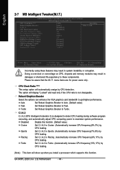
...used for it. (Default Value) Voltage Set to PWM when you installed and sets the optimal CPU Smart FAN control mode for CPU fans with a 3-pin fan power cable. However, some 4-pin CPU fan power cables are not designed following Intel 4-Wire fans PWM control specifications. PWM Set to... Voltage when you use a CPU fan with Easy Tune based on CPU temperature. Note: In fact, the Voltage option can adjust the fan speed with a 4-pin fan power cable. Enabled When this ...
...used for it. (Default Value) Voltage Set to PWM when you installed and sets the optimal CPU Smart FAN control mode for CPU fans with a 3-pin fan power cable. However, some 4-pin CPU fan power cables are not designed following Intel 4-Wire fans PWM control specifications. PWM Set to... Voltage when you use a CPU fan with Easy Tune based on CPU temperature. Note: In fact, the Voltage option can adjust the fan speed with a 4-pin fan power cable. Enabled When this ...
Manual
Page 44
...GA-945PL-(D)S3 (rev. 2.0) Motherboard - 44 - Robust Graphics Booster Select the options can enhance the VGA graphics card bandwidth to Turbo. Auto Set Robust Graphics Booster to Auto. (Default value) Fast Set Robust Graphics Booster to maximize system performance. The option will automatically assign by CPU loading. C.I.A.2 C.I.A.2 (CPU... these features may result in system instability or corruption. Set C.I.A.2 to Racing. (Automatically increase CPU frequency(9%,11%) by CPU loading. (Note) This item will show up when you install a processor which supports this ...
...GA-945PL-(D)S3 (rev. 2.0) Motherboard - 44 - Robust Graphics Booster Select the options can enhance the VGA graphics card bandwidth to Turbo. Auto Set Robust Graphics Booster to Auto. (Default value) Fast Set Robust Graphics Booster to maximize system performance. The option will automatically assign by CPU loading. C.I.A.2 C.I.A.2 (CPU... these features may result in system instability or corruption. Set C.I.A.2 to Racing. (Automatically increase CPU frequency(9%,11%) by CPU loading. (Note) This item will show up when you install a processor which supports this ...
Manual
Page 45
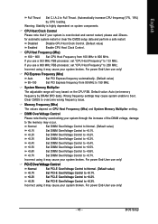
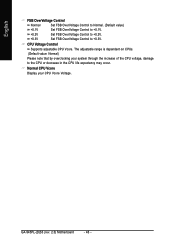
... may occur. DIMM OverVoltage Control Please note that if your system broken. For power End-User use only! Default value: Auto (set "CPU Host Frequency" to 600 MHz. Normal Set DIMM OverVoltage Control to Normal. (Default value) +0.1V +0.2V Set DIMM OverVoltage Control to +0....data and perform a safe restart. System Memory Multiplier The adjustable range will vary based on the CPU FSB. Incorrect using it may cause your system is highly dependent on CPU Host Frequency (Mhz) and System Memory Multiplier setting. Set DIMM OverVoltage Control to +0.2V. +0.3V...
... may occur. DIMM OverVoltage Control Please note that if your system broken. For power End-User use only! Default value: Auto (set "CPU Host Frequency" to 600 MHz. Normal Set DIMM OverVoltage Control to Normal. (Default value) +0.1V +0.2V Set DIMM OverVoltage Control to +0....data and perform a safe restart. System Memory Multiplier The adjustable range will vary based on the CPU FSB. Incorrect using it may cause your system is highly dependent on CPU Host Frequency (Mhz) and System Memory Multiplier setting. Set DIMM OverVoltage Control to +0.2V. +0.3V...
Manual
Page 46
... Display your system through the increase of the CPU voltage, damage to +0.3V. CPU Voltage Control Supports adjustable CPU Vcore. English FSB OverVoltage Control Normal Set FSB OverVoltage Control to Normal. (Default value) +0.1V Set FSB OverVoltage Control to +0....1V. +0.2V Set FSB OverVoltage Control to +0.2V. +0.3V Set FSB OverVoltage Control to the CPU or decrease in the CPU life expectancy may occur. GA-945PL-(D)S3 (rev. 2.0) Motherboard - 46 - The adjustable range is dependent on CPUs. (Default value: Normal) Please note that...
... Display your system through the increase of the CPU voltage, damage to +0.3V. CPU Voltage Control Supports adjustable CPU Vcore. English FSB OverVoltage Control Normal Set FSB OverVoltage Control to Normal. (Default value) +0.1V Set FSB OverVoltage Control to +0....1V. +0.2V Set FSB OverVoltage Control to +0.2V. +0.3V Set FSB OverVoltage Control to the CPU or decrease in the CPU life expectancy may occur. GA-945PL-(D)S3 (rev. 2.0) Motherboard - 46 - The adjustable range is dependent on CPUs. (Default value: Normal) Please note that...
Manual
Page 55
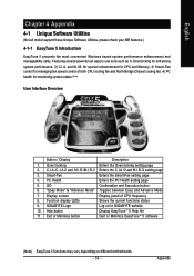
...5 Introduction EasyTune 5 presents the most convenient Windows based system performance enhancement and manageability utility. Display screen Display panel of both CPU cooling fan and North-Bridge Chipset cooling fan, 4) PC health for monitoring system status.(Note) User Interface Overview Button / ... and Advance Mode 7. Smart-Fan Enters the Smart-Fan setting page 4. Featuring several powerful yet easy to GIGABYTE website 10. for special enhancement for CPU and Memory, 3) Smart-Fan control for enhancing system performance, 2) C.I.A. Help button Display EasyTuneTM 5 Help...
...5 Introduction EasyTune 5 presents the most convenient Windows based system performance enhancement and manageability utility. Display screen Display panel of both CPU cooling fan and North-Bridge Chipset cooling fan, 4) PC health for monitoring system status.(Note) User Interface Overview Button / ... and Advance Mode 7. Smart-Fan Enters the Smart-Fan setting page 4. Featuring several powerful yet easy to GIGABYTE website 10. for special enhancement for CPU and Memory, 3) Smart-Fan control for enhancing system performance, 2) C.I.A. Help button Display EasyTuneTM 5 Help...


