Manual
Page 4
... Back Panel Introduction 17 1-7 Connectors Introduction 18 Chapter 2 BIOS Setup 29 The Main Menu (For example: GA-945P-DS3 BIOS Ver. Table of Contents ItemChecklist ...6 OptionalAccessories ...6 GA-945P-DS3/GA-945P-S3 Motherboard Layout 7 Block Diagram ...8 Chapter 1 Hardware Installation 9 1-1 Considerations Prior to Installation 9 1-2 Feature Summary 10 1-3 Installation of the CPU and CPU Cooler 12 1-3-1 Installation of the CPU 12 1-3-2 Installation of the CPU Cooler 13 1-4 Installation of Memory 14 1-5 Installation of Expansion Cards 16 1-6 I .T 44 2-8 Load Fail-Safe Defaults...
... Back Panel Introduction 17 1-7 Connectors Introduction 18 Chapter 2 BIOS Setup 29 The Main Menu (For example: GA-945P-DS3 BIOS Ver. Table of Contents ItemChecklist ...6 OptionalAccessories ...6 GA-945P-DS3/GA-945P-S3 Motherboard Layout 7 Block Diagram ...8 Chapter 1 Hardware Installation 9 1-1 Considerations Prior to Installation 9 1-2 Feature Summary 10 1-3 Installation of the CPU and CPU Cooler 12 1-3-1 Installation of the CPU 12 1-3-2 Installation of the CPU Cooler 13 1-4 Installation of Memory 14 1-5 Installation of Expansion Cards 16 1-6 I .T 44 2-8 Load Fail-Safe Defaults...
Manual
Page 10
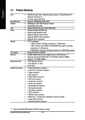
...3 PCI slots Internal Connectors Š 1 24-pin ATX power connector Š 1 4-pin ATX 12V power connector Š 1 floppy connector Š 1 IDE connector Š 4 SATA 3Gb/s connectors Š 1 CPU fan connector Š 1 system fan connector Š 1 power fan connector Š 1 northbridge fan connector Š 1 front panel connector Š 1 front audio connector Š 1 CD In connector Š 1 S/PDIF In/Out connector Š 2 USB 2.0/1.1 connectors for additional 4 ports by cables Š 1 power LED connector Š 1 Chassis Intrusion connector "*" Only the GA-945P-DS3...
...3 PCI slots Internal Connectors Š 1 24-pin ATX power connector Š 1 4-pin ATX 12V power connector Š 1 floppy connector Š 1 IDE connector Š 4 SATA 3Gb/s connectors Š 1 CPU fan connector Š 1 system fan connector Š 1 power fan connector Š 1 northbridge fan connector Š 1 front panel connector Š 1 front audio connector Š 1 CD In connector Š 1 S/PDIF In/Out connector Š 2 USB 2.0/1.1 connectors for additional 4 ports by cables Š 1 power LED connector Š 1 Chassis Intrusion connector "*" Only the GA-945P-DS3...
Manual
Page 13
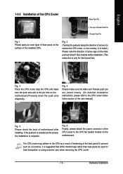
... tape rather than heat paste be used for detailed installation instructions, please refer to the CPU fan header located on the motherboard. Hardware Installation Fig. 2 (Turning the push pin along the direction of arrow is to remove the CPU cooler, on the contrary, is to install.) Please note the direction of the installed CPU. The CPU cooler may adhere to the pin hole on the surface of arrow...
... tape rather than heat paste be used for detailed installation instructions, please refer to the CPU fan header located on the motherboard. Hardware Installation Fig. 2 (Turning the push pin along the direction of arrow is to remove the CPU cooler, on the contrary, is to install.) Please note the direction of the installed CPU. The CPU cooler may adhere to the pin hole on the surface of arrow...
Manual
Page 15
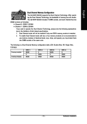
The following explanations due to use memory modules of identical brand, size, chips, and speed), you must install them into DIMM sockets of the same color. Hardware Installation Dual Channel mode will double. English Dual Channel Memory Configuration The GA-945P-DS3/S3 supports the Dual Channel Technology. To enable Dual Channel mode with two or four memory modules (it is recommended to the limitation of memory bus will not be enabled if only one DDRII memory module is a Dual Channel Memory configuration table: (DS: Double...
The following explanations due to use memory modules of identical brand, size, chips, and speed), you must install them into DIMM sockets of the same color. Hardware Installation Dual Channel mode will double. English Dual Channel Memory Configuration The GA-945P-DS3/S3 supports the Dual Channel Technology. To enable Dual Channel mode with two or four memory modules (it is recommended to the limitation of memory bus will not be enabled if only one DDRII memory module is a Dual Channel Memory configuration table: (DS: Double...
Manual
Page 18
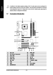
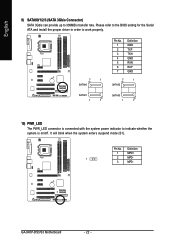
Please refer to the 2-/4-/6-/8- channel audio setup steps for detailed software configuration information. 1-7 Connectors Introduction 1 3 6 2 12 5 17 18 9 8 16 13 14 4 1) ATX_12V 2) ATX (Power Connector) 3) CPU_FAN 4) SYS_FAN 5) PWR_FAN 6) NB_FAN 7) FDD 8) IDE1 9) SATAII0/1/2/3 7 15 10 11 10) PWR_LED 11) F_PANEL 12) F_AUDIO 13) CD_IN 14) SPDIF_IO 15) F_USB1/F_USB2 16) CI 17) CLR_CMOS 18) BATTERY GA-945P-DS3/S3 Motherboard - 18 - Only microphones still MUST be...
Please refer to the 2-/4-/6-/8- channel audio setup steps for detailed software configuration information. 1-7 Connectors Introduction 1 3 6 2 12 5 17 18 9 8 16 13 14 4 1) ATX_12V 2) ATX (Power Connector) 3) CPU_FAN 4) SYS_FAN 5) PWR_FAN 6) NB_FAN 7) FDD 8) IDE1 9) SATAII0/1/2/3 7 15 10 11 10) PWR_LED 11) F_PANEL 12) F_AUDIO 13) CD_IN 14) SPDIF_IO 15) F_USB1/F_USB2 16) CI 17) CLR_CMOS 18) BATTERY GA-945P-DS3/S3 Motherboard - 18 - Only microphones still MUST be...
Manual
Page 20
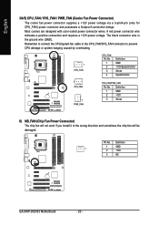
... GA-945P-DS3/S3 Motherboard - 20 - Most coolers are designed with color-coded power connector wires. Remember to connect the CPU/system fan cable to the CPU_FAN/SYS_FAN connector to prevent CPU damage or system hanging caused by overheating. 1 CPU_FAN CPU_FAN: Pin No. 1 2 3 4 Definition GND +12V/Speed Control Sense Speed Control 1 SYS_FAN 1 PWR_FAN SYS_FAN/PWR_FAN: Pin No. English 3/4/5) CPU_FAN / SYS_FAN / PWR_FAN (Cooler Fan Power Connector) The cooler fan power connector supplies a +12V power voltage via a 3-pin/4-pin (only for CPU_FAN) power connector and...
... GA-945P-DS3/S3 Motherboard - 20 - Most coolers are designed with color-coded power connector wires. Remember to connect the CPU/system fan cable to the CPU_FAN/SYS_FAN connector to prevent CPU damage or system hanging caused by overheating. 1 CPU_FAN CPU_FAN: Pin No. 1 2 3 4 Definition GND +12V/Speed Control Sense Speed Control 1 SYS_FAN 1 PWR_FAN SYS_FAN/PWR_FAN: Pin No. English 3/4/5) CPU_FAN / SYS_FAN / PWR_FAN (Cooler Fan Power Connector) The cooler fan power connector supplies a +12V power voltage via a 3-pin/4-pin (only for CPU_FAN) power connector and...
Manual
Page 21
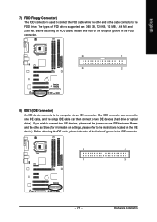
... IDE connector. Hardware Installation If you wish to connect two IDE devices, please set the jumper on one IDE cable, and the single IDE cable can then connect to the instructions located on settings, please refer to two IDE devices (hard drive or optical drive). Before attaching the FDD cable, please take note of FDD drives supported are: 360 KB, 720 KB, 1.2 MB, 1.44 MB and 2.88 MB. English 7) FDD (Floppy Connector) The FDD connector is used to connect...
... IDE connector. Hardware Installation If you wish to connect two IDE devices, please set the jumper on one IDE cable, and the single IDE cable can then connect to the instructions located on settings, please refer to two IDE devices (hard drive or optical drive). Before attaching the FDD cable, please take note of FDD drives supported are: 360 KB, 720 KB, 1.2 MB, 1.44 MB and 2.88 MB. English 7) FDD (Floppy Connector) The FDD connector is used to connect...
Manual
Page 22
Pin No. GA-945P-DS3/S3 Motherboard - 22 - English 9) SATAII0/1/2/3 (SATA 3Gb/s Connector) SATA 3Gb/s can provide up to indicate whether the system is connected with the system power indicator to 300MB/s transfer rate. Definition 1 MPD+ 1 2 MPD- 3 MPD- Please refer to the BIOS setting for the Serial ATA and install the proper driver in order to work properly. 7 1 SATAII0 Pin No. 1 2 3 4 5 6 7 Definition GND TXP TXN GND RXN RXP...
Pin No. GA-945P-DS3/S3 Motherboard - 22 - English 9) SATAII0/1/2/3 (SATA 3Gb/s Connector) SATA 3Gb/s can provide up to indicate whether the system is connected with the system power indicator to 300MB/s transfer rate. Definition 1 MPD+ 1 2 MPD- 3 MPD- Please refer to the BIOS setting for the Serial ATA and install the proper driver in order to work properly. 7 1 SATAII0 Pin No. 1 2 3 4 5 6 7 Definition GND TXP TXN GND RXN RXP...
Manual
Page 23
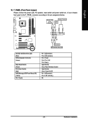
...front panel to the F_PANEL connector according to the pin assignment below. Message LED/ Power/ Sleep LED Speaker Connector Power Switch MSG+ MSG- Hardware Installation RESRES+ NC Reset Switch IDE Hard Disk Active LED HD (IDE Hard Disk Active LED) (Blue) SPEAK (Speaker Connector) (Amber) RES (Reset Switch) (Green) PW (Power Switch) (Red) MSG (Message LED/Power/Sleep LED) (Yellow) NC ( Purple) Pin 1: LED anode(+) Pin 2: LED cathode(-) Pin 1: Power Pin 2- Pin 3: NC Pin 4: Data(-) Open: Normal Close: Reset Hardware System Open: Normal Close: Power On/Off Pin 1: LED anode(+) Pin 2: LED...
...front panel to the F_PANEL connector according to the pin assignment below. Message LED/ Power/ Sleep LED Speaker Connector Power Switch MSG+ MSG- Hardware Installation RESRES+ NC Reset Switch IDE Hard Disk Active LED HD (IDE Hard Disk Active LED) (Blue) SPEAK (Speaker Connector) (Amber) RES (Reset Switch) (Green) PW (Power Switch) (Red) MSG (Message LED/Power/Sleep LED) (Yellow) NC ( Purple) Pin 1: LED anode(+) Pin 2: LED cathode(-) Pin 1: Power Pin 2- Pin 3: NC Pin 4: Data(-) Open: Normal Close: Reset Hardware System Open: Normal Close: Power On/Off Pin 1: LED anode(+) Pin 2: LED...
Manual
Page 24
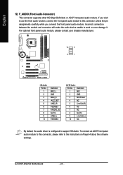
... panel audio module to the instructions on Page 64 about the software settings. Check the pin assignments carefully while you wish to use the front audio function, connect the front panel audio module to this connector, please refer to this connector. GA-945P-DS3/S3 Motherboard - 24 - Incorrect connection between the module and connector will make the audio device unable to support HD Audio. For optional front panel audio module, please contact your chassis manufacturer. 10 9 2 1 HD Audio: Pin...
... panel audio module to the instructions on Page 64 about the software settings. Check the pin assignments carefully while you wish to use the front audio function, connect the front panel audio module to this connector, please refer to this connector. GA-945P-DS3/S3 Motherboard - 24 - Incorrect connection between the module and connector will make the audio device unable to support HD Audio. For optional front panel audio module, please contact your chassis manufacturer. 10 9 2 1 HD Audio: Pin...
Manual
Page 32
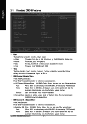
... detection step and allow for faster system start up . is display-only Month Day The month, Jan. GA-945P-DS3/S3 Motherboard - 32 - For example, 1 p.m. You can use one of three methods: Auto Allows BIOS to Sat, determined by the BIOS and is 13:0:0. You can manually input the correct settings Access Mode Use this option for the hard drive. IDE/SATA Device Setup. IDE Channel 0 Master/Slave IDE/SATA Device Setup. Week The week, from 1999 through...
... detection step and allow for faster system start up . is display-only Month Day The month, Jan. GA-945P-DS3/S3 Motherboard - 32 - For example, 1 p.m. You can use one of three methods: Auto Allows BIOS to Sat, determined by the BIOS and is 13:0:0. You can manually input the correct settings Access Mode Use this option for the hard drive. IDE/SATA Device Setup. IDE Channel 0 Master/Slave IDE/SATA Device Setup. Week The week, from 1999 through...
Manual
Page 37
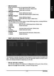
... USB storage detect This option allows users to decide whether to the following information for diagnosing your LAN cable: When No LAN Cable Is Attached... SMART LAN (LAN Cable Diagnostic Function) CMOS Setup Utility-Copyright (C) 1984-2007 Award Software SMART LAN Start detecting at Port..... BIOS Setup Onboard H/W LAN Enabled Enable Onboard H/W LAN function. (Default value) Disabled Disable this function if you are not using onboard USB 2.0 feature. Refer to detect USB storage devices, including USB flash drives and USB hard drives during POST. English USB 2.0 Controller...
... USB storage detect This option allows users to decide whether to the following information for diagnosing your LAN cable: When No LAN Cable Is Attached... SMART LAN (LAN Cable Diagnostic Function) CMOS Setup Utility-Copyright (C) 1984-2007 Award Software SMART LAN Start detecting at Port..... BIOS Setup Onboard H/W LAN Enabled Enable Onboard H/W LAN function. (Default value) Disabled Disable this function if you are not using onboard USB 2.0 feature. Refer to detect USB storage devices, including USB flash drives and USB hard drives during POST. English USB 2.0 Controller...
Manual
Page 42
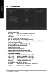
.... GA-945P-DS3/S3 Motherboard - 42 - Current Voltage(V) Vcore / DDR18V / +3.3V / +12V Detect system's voltage status automatically. Monitor CPU temperature at 70oC / 158oF. Case Opened If the case is closed, "Case Opened" will restart. Monitor CPU temperature at next boot. Disable this function. (Default value) CPU/POWER/SYSTEM FAN Fail Warning Disabled Enabled Disable the fan fail warning function. (Default value) Enable the fan fail warning function. If you want to reset "Case Opened" value, set "Reset Case Open Status" to "Enabled" and save CMOS...
.... GA-945P-DS3/S3 Motherboard - 42 - Current Voltage(V) Vcore / DDR18V / +3.3V / +12V Detect system's voltage status automatically. Monitor CPU temperature at 70oC / 158oF. Case Opened If the case is closed, "Case Opened" will restart. Monitor CPU temperature at next boot. Disable this function. (Default value) CPU/POWER/SYSTEM FAN Fail Warning Disabled Enabled Disable the fan fail warning function. (Default value) Enable the fan fail warning function. If you want to reset "Case Opened" value, set "Reset Case Open Status" to "Enabled" and save CMOS...
Manual
Page 47
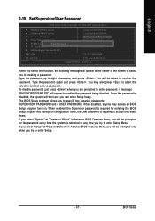
... disabled. Type the password again and press . The BIOS Setup program allows you can enter Setup freely. When disabled, anyone may also press to abort the selection and not enter a password. BIOS Setup English 2-10 Set Supervisor/User Password CMOS Setup Utility-Copyright (C) 1984-2007 Award Software ` Standard CMOS Features ` Advanced BIOS Features ` Integrated Peripherals ` Power Management Setup ` PnP/PCI ConfigurationEsnter Password: ` PC Health Status ` MB Intelligent Tweaker(M.I.T.) Load Fail-Safe Defaults Load Optimized Defaults Set Supervisor Password Set User Password...
... disabled. Type the password again and press . The BIOS Setup program allows you can enter Setup freely. When disabled, anyone may also press to abort the selection and not enter a password. BIOS Setup English 2-10 Set Supervisor/User Password CMOS Setup Utility-Copyright (C) 1984-2007 Award Software ` Standard CMOS Features ` Advanced BIOS Features ` Integrated Peripherals ` Power Management Setup ` PnP/PCI ConfigurationEsnter Password: ` PC Health Status ` MB Intelligent Tweaker(M.I.T.) Load Fail-Safe Defaults Load Optimized Defaults Set Supervisor Password Set User Password...
Manual
Page 48
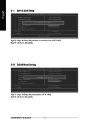
... RTC CMOS. Type "N" will quit the Setup Utility and save the user setup value to Setup Utility. Type "N" will return to Setup Utility. 2-12 Exit Without Saving CMOS Setup Utility-Copyright (C) 1984-2007 Award Software ` Standard CMOS Features ` Advanced BIOS Features ` Integrated Peripherals ` Power Management Setup ` PnP/PCI Configurations ` PC Health Status ` MB Intelligent Tweaker(M.I .T.) ESC: Quit F8: Q-Flash KLJI: Select Item F10: Save & Exit Setup Save Data to CMOS Type "Y" will return to RTC CMOS. GA-945P-DS3/S3 Motherboard...
... RTC CMOS. Type "N" will quit the Setup Utility and save the user setup value to Setup Utility. Type "N" will return to Setup Utility. 2-12 Exit Without Saving CMOS Setup Utility-Copyright (C) 1984-2007 Award Software ` Standard CMOS Features ` Advanced BIOS Features ` Integrated Peripherals ` Power Management Setup ` PnP/PCI Configurations ` PC Health Status ` MB Intelligent Tweaker(M.I .T.) ESC: Quit F8: Q-Flash KLJI: Select Item F10: Save & Exit Setup Save Data to CMOS Type "Y" will return to RTC CMOS. GA-945P-DS3/S3 Motherboard...
Manual
Page 49
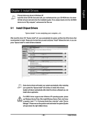
... with your motherboard into your CD-ROM drive, the driver CD-title will auto start and show a question mark "?" After restarting your system automatically. Please remove the question mark and restart the system (System will continue to install other drivers. System will scan automatically the system and then list all the drivers that recommended to install all items defaulted. Insert the driver CD-title...
... with your motherboard into your CD-ROM drive, the driver CD-title will auto start and show a question mark "?" After restarting your system automatically. Please remove the question mark and restart the system (System will continue to install other drivers. System will scan automatically the system and then list all the drivers that recommended to install all items defaulted. Insert the driver CD-title...
Manual
Page 54
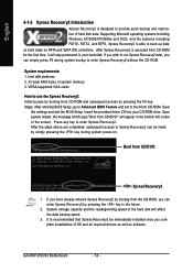
... the data backup speed. 3. GA-945P-DS3/S3 Motherboard . . . . - 54 - System requirements: 1. Press any key to Xpress Recovery2 can be immediately installed once you can simply press F9 during system power-on PATA and SATA IDE controllers. After the steps above are completed, subsequent access to startup XpressRecovery2..... After Xpress Recovery2 is executed from CD-ROM for 945P-DS3 F2c . . . . :BIOS Setup/Q-Flash : XpressRecovery2 : Boot Menu : Qflash 01/31...
... the data backup speed. 3. GA-945P-DS3/S3 Motherboard . . . . - 54 - System requirements: 1. Press any key to Xpress Recovery2 can be immediately installed once you can simply press F9 during system power-on PATA and SATA IDE controllers. After the steps above are completed, subsequent access to startup XpressRecovery2..... After Xpress Recovery2 is executed from CD-ROM for 945P-DS3 F2c . . . . :BIOS Setup/Q-Flash : XpressRecovery2 : Boot Menu : Qflash 01/31...
Manual
Page 56
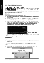
..., download the latest compressed BIOS update file that allows the user to select Update BIOS from Drive and press ENTER. Inadequate BIOS flashing may result in BIOS Setup. Free size : 0 DEL : Delete - 56 - Select the floppy drive or hard drive where the BIOS file is potentially risky, please do it with caution. Restart the system. If you from Drive Sa0vefilBeI(Os)SfotounDdrive EnteFr l:oRppuyn A :Move ESC:Reset :Power Off HDD 0-0 Total size : 0 F5 : Refresh GA-945P-DS3/S3 Motherboard . . . . English 4-1-3 Flash BIOS...
..., download the latest compressed BIOS update file that allows the user to select Update BIOS from Drive and press ENTER. Inadequate BIOS flashing may result in BIOS Setup. Free size : 0 DEL : Delete - 56 - Select the floppy drive or hard drive where the BIOS file is potentially risky, please do it with caution. Restart the system. If you from Drive Sa0vefilBeI(Os)SfotounDdrive EnteFr l:oRppuyn A :Move ESC:Reset :Power Off HDD 0-0 Total size : 0 F5 : Refresh GA-945P-DS3/S3 Motherboard . . . . English 4-1-3 Flash BIOS...
Manual
Page 58
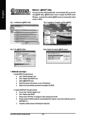
... Update" icon b. Update BIOS NOT through Internet a. d. GA-945P-DS3/S3 Motherboard . . . . - 58 - Methods and steps: I. Select the exact model name on your motherboard e. Do not click "Internet Update" icon b. Please select "All Files" in dialog box while opening the old file. Please search for BIOS unzip file, downloading from internet or any other methods (such as: 945PDS3.F1). e. Installation Complete and Run @BIOS Click Start/ Programs/ GIGABYTE/@BIOS Select @BIOS...
... Update" icon b. Update BIOS NOT through Internet a. d. GA-945P-DS3/S3 Motherboard . . . . - 58 - Methods and steps: I. Select the exact model name on your motherboard e. Do not click "Internet Update" icon b. Please select "All Files" in dialog box while opening the old file. Please search for BIOS unzip file, downloading from internet or any other methods (such as: 945PDS3.F1). e. Installation Complete and Run @BIOS Click Start/ Programs/ GIGABYTE/@BIOS Select @BIOS...
Manual
Page 65
...do these options. AWARD BIOS Beep Codes 1 short: System boots successfully 2 short: CMOS setting error 1 long 1 short: DRAM or M/B error 1 long 2 short: Monitor or display card error 1 long 3 short: Keyboard error 1 long 9 short: BIOS ROM error Continuous long beeps: DRAM error Continuous short beeps: Power error - 65 - Turn off the on standby after entering BIOS menu and you are only for ? Press Del to the battery holder. 5. Question 4: Why do I cannot see these beeps usually stand for reference purposes. Appendix Why? If your board has a Clear CMOS jumper, please refer...
...do these options. AWARD BIOS Beep Codes 1 short: System boots successfully 2 short: CMOS setting error 1 long 1 short: DRAM or M/B error 1 long 2 short: Monitor or display card error 1 long 3 short: Keyboard error 1 long 9 short: BIOS ROM error Continuous long beeps: DRAM error Continuous short beeps: Power error - 65 - Turn off the on standby after entering BIOS menu and you are only for ? Press Del to the battery holder. 5. Question 4: Why do I cannot see these beeps usually stand for reference purposes. Appendix Why? If your board has a Clear CMOS jumper, please refer...


