Manual
Page 1
GA-945P-DS3/S3 Intel® CoreTM 2 Extreme dual-core / CoreTM 2 Duo / Intel® Pentium® D / Pentium® 4 / Celeron® D LGA775 Processor Motherboard User's Manual Rev. 3301 12ME-945PDS3-3301R * The WEEE marking on the product indicates this product must not be disposed of with user's other household waste and must be handed over to a designated collection point for the recycling of waste electrical and electronic equipment!! * The WEEE marking applies only in European Union's member states.
GA-945P-DS3/S3 Intel® CoreTM 2 Extreme dual-core / CoreTM 2 Duo / Intel® Pentium® D / Pentium® 4 / Celeron® D LGA775 Processor Motherboard User's Manual Rev. 3301 12ME-945PDS3-3301R * The WEEE marking on the product indicates this product must not be disposed of with user's other household waste and must be handed over to a designated collection point for the recycling of waste electrical and electronic equipment!! * The WEEE marking applies only in European Union's member states.
Manual
Page 2
Motherboard GA-945P-DS3/GA-945P-S3 Oct. 27, 2006 Motherboard GA-945P-DS3/ GA-945P-S3 Oct. 27, 2006
Motherboard GA-945P-DS3/GA-945P-S3 Oct. 27, 2006 Motherboard GA-945P-DS3/ GA-945P-S3 Oct. 27, 2006
Manual
Page 4
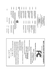
Table of Contents ItemChecklist ...6 OptionalAccessories ...6 GA-945P-DS3/GA-945P-S3 Motherboard Layout 7 Block Diagram ...8 Chapter 1 Hardware Installation 9 1-1 Considerations Prior to Installation 9 1-2 Feature Summary 10 1-3 Installation of the CPU and CPU Cooler 12 1-3-1 Installation of the ... Configurations 41 2-6 PC Health Status 42 2-7 MB Intelligent Tweaker(M.I /O Back Panel Introduction 17 1-7 Connectors Introduction 18 Chapter 2 BIOS Setup 29 The Main Menu (For example: GA-945P-DS3 BIOS Ver.
Table of Contents ItemChecklist ...6 OptionalAccessories ...6 GA-945P-DS3/GA-945P-S3 Motherboard Layout 7 Block Diagram ...8 Chapter 1 Hardware Installation 9 1-1 Considerations Prior to Installation 9 1-2 Feature Summary 10 1-3 Installation of the CPU and CPU Cooler 12 1-3-1 Installation of the ... Configurations 41 2-6 PC Health Status 42 2-7 MB Intelligent Tweaker(M.I /O Back Panel Introduction 17 1-7 Connectors Introduction 18 Chapter 2 BIOS Setup 29 The Main Menu (For example: GA-945P-DS3 BIOS Ver.
Manual
Page 7
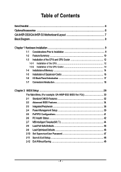
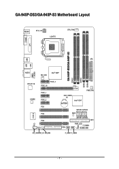
GA-945P-DS3/GA-945P-S3 Motherboard Layout KB_MS ATX_12V LGA775 CPU_FAN COMA LPT GA-945P-DS3/GA-945P-S3 DDRII1 DDRII2 DDRII3 DDRII4 USB USB LAN ATX F_AUDIO AUDIO NB_FAN Intel® 945P RTL8111B CODEC CI IT8718 PCIE_16 PCIE_3 PCIE_1 PCIE_2 PCI1 PCI2 PCI3 CD_IN SPDIF_IO SYS_FAN CLR_CMOS BATTERY Intel® ICH7 PWR_FAN SATAII0 SATAII2 BIOS SATAII1 SATAII3 IDE1 PWR_LED F_PANEL FDD F_USB1 F_USB2 - 7 -
GA-945P-DS3/GA-945P-S3 Motherboard Layout KB_MS ATX_12V LGA775 CPU_FAN COMA LPT GA-945P-DS3/GA-945P-S3 DDRII1 DDRII2 DDRII3 DDRII4 USB USB LAN ATX F_AUDIO AUDIO NB_FAN Intel® 945P RTL8111B CODEC CI IT8718 PCIE_16 PCIE_3 PCIE_1 PCIE_2 PCI1 PCI2 PCI3 CD_IN SPDIF_IO SYS_FAN CLR_CMOS BATTERY Intel® ICH7 PWR_FAN SATAII0 SATAII2 BIOS SATAII1 SATAII3 IDE1 PWR_LED F_PANEL FDD F_USB1 F_USB2 - 7 -
Manual
Page 10
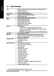
GA-945P-DS3/S3 Motherboard - 10 - English 1-2 Feature Summary CPU Š LGA775 for Intel® CoreTM 2 Extreme dual-core/CoreTM 2 Duo/Pentium® D/ Pentium® 4/Celeron® D Š L2 cache varies with CPU Front Side Bus Š Supports 1066/800/533 MHz FSB Chipset Š Northbridge: Intel® 945P Express Chipset Š Southbridge: Intel&#...Š 1 S/PDIF In/Out connector Š 2 USB 2.0/1.1 connectors for additional 4 ports by cables Š 1 power LED connector Š 1 Chassis Intrusion connector "*" Only the GA-945P-DS3 adopts All-Solid Capacitor design.
GA-945P-DS3/S3 Motherboard - 10 - English 1-2 Feature Summary CPU Š LGA775 for Intel® CoreTM 2 Extreme dual-core/CoreTM 2 Duo/Pentium® D/ Pentium® 4/Celeron® D Š L2 cache varies with CPU Front Side Bus Š Supports 1066/800/533 MHz FSB Chipset Š Northbridge: Intel® 945P Express Chipset Š Southbridge: Intel&#...Š 1 S/PDIF In/Out connector Š 2 USB 2.0/1.1 connectors for additional 4 ports by cables Š 1 power LED connector Š 1 Chassis Intrusion connector "*" Only the GA-945P-DS3 adopts All-Solid Capacitor design.
Manual
Page 12
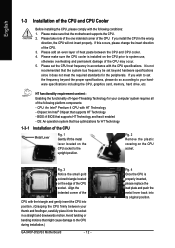
... and has it into the socket in a straight and downwards motion. Fig. 2 Remove the plastic covering on the CPU socket to the CPU during installation.) GA-945P-DS3/S3 Motherboard - 12 - Align the indented corner of the CPU with the CPU specifications. Please make sure the CPU cooler is installed on the edge of...
... and has it into the socket in a straight and downwards motion. Fig. 2 Remove the plastic covering on the CPU socket to the CPU during installation.) GA-945P-DS3/S3 Motherboard - 12 - Align the indented corner of the CPU with the CPU specifications. Please make sure the CPU cooler is installed on the edge of...
Manual
Page 14
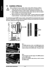
... one direction. Reverse the installation steps when you are designed so that memory of the DIMM sockets to insert the module, please switch the direction. GA-945P-DS3/S3 Motherboard - 14 - It is recommended that they can be used can only fit in one direction.
... one direction. Reverse the installation steps when you are designed so that memory of the DIMM sockets to insert the module, please switch the direction. GA-945P-DS3/S3 Motherboard - 14 - It is recommended that they can be used can only fit in one direction.
Manual
Page 15
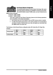
Dual Channel mode will double. Hardware Installation English Dual Channel Memory Configuration The GA-945P-DS3/S3 supports the Dual Channel Technology. The GA-945P-DS3/S3 includes 4 DIMM sockets, and each Channel has two DIMM sockets as following: Channel 0 : DDRII1, DDRII2 Channel 1 : DDRII3, DDRII4 If you must install them into DIMM ...
Dual Channel mode will double. Hardware Installation English Dual Channel Memory Configuration The GA-945P-DS3/S3 supports the Dual Channel Technology. The GA-945P-DS3/S3 includes 4 DIMM sockets, and each Channel has two DIMM sockets as following: Channel 0 : DDRII1, DDRII2 Channel 1 : DDRII3, DDRII4 If you must install them into DIMM ...
Manual
Page 16
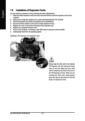
GA-945P-DS3/S3 Motherboard - 16 - Be sure the metal contacts on the card are indeed seated in motherboard. 4. Install related driver from the computer. 3. Make sure your VGA ...
GA-945P-DS3/S3 Motherboard - 16 - Be sure the metal contacts on the card are indeed seated in motherboard. 4. Install related driver from the computer. 3. Make sure your VGA ...
Manual
Page 18
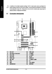
... 7) FDD 8) IDE1 9) SATAII0/1/2/3 7 15 10 11 10) PWR_LED 11) F_PANEL 12) F_AUDIO 13) CD_IN 14) SPDIF_IO 15) F_USB1/F_USB2 16) CI 17) CLR_CMOS 18) BATTERY GA-945P-DS3/S3 Motherboard - 18 - Please refer to perform different functions via the audio software. Only microphones still MUST be reconfigured to the 2-/4-/6-/8-
... 7) FDD 8) IDE1 9) SATAII0/1/2/3 7 15 10 11 10) PWR_LED 11) F_PANEL 12) F_AUDIO 13) CD_IN 14) SPDIF_IO 15) F_USB1/F_USB2 16) CI 17) CLR_CMOS 18) BATTERY GA-945P-DS3/S3 Motherboard - 18 - Please refer to perform different functions via the audio software. Only microphones still MUST be reconfigured to the 2-/4-/6-/8-
Manual
Page 20
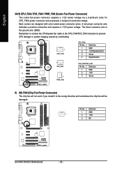
... cooler fan power connector supplies a +12V power voltage via a 3-pin/4-pin (only for CPU_FAN) power connector and possesses a foolproof connection design. Definition 1 GND 1 2 +12V 3 NC GA-945P-DS3/S3 Motherboard - 20 - Most coolers are designed with color-coded power connector wires.
... cooler fan power connector supplies a +12V power voltage via a 3-pin/4-pin (only for CPU_FAN) power connector and possesses a foolproof connection design. Definition 1 GND 1 2 +12V 3 NC GA-945P-DS3/S3 Motherboard - 20 - Most coolers are designed with color-coded power connector wires.
Manual
Page 22
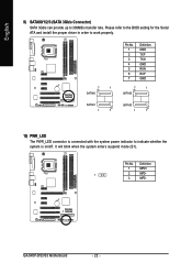
It will blink when the system enters suspend mode (S1). Definition 1 MPD+ 1 2 MPD- 3 MPD- GA-945P-DS3/S3 Motherboard - 22 - English 9) SATAII0/1/2/3 (SATA 3Gb/s Connector) SATA 3Gb/s can provide up to indicate whether the system is connected with the system power indicator to ...
It will blink when the system enters suspend mode (S1). Definition 1 MPD+ 1 2 MPD- 3 MPD- GA-945P-DS3/S3 Motherboard - 22 - English 9) SATAII0/1/2/3 (SATA 3Gb/s Connector) SATA 3Gb/s can provide up to indicate whether the system is connected with the system power indicator to ...
Manual
Page 24
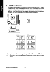
... this connector. Incorrect connection between the module and connector will make the audio device unable to the instructions on Page 64 about the software settings. GA-945P-DS3/S3 Motherboard - 24 - For optional front panel audio module, please contact your chassis manufacturer. 10 9 2 1 HD Audio: Pin No. 1 2 3 4 5 6 7 8 9 10 Definition MIC2_L GND MIC2_R -ACZ_DET LINE2_R...
... this connector. Incorrect connection between the module and connector will make the audio device unable to the instructions on Page 64 about the software settings. GA-945P-DS3/S3 Motherboard - 24 - For optional front panel audio module, please contact your chassis manufacturer. 10 9 2 1 HD Audio: Pin No. 1 2 3 4 5 6 7 8 9 10 Definition MIC2_L GND MIC2_R -ACZ_DET LINE2_R...
Manual
Page 26
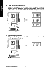
... USB cable, incorrect connection between the cable and connector will make the device unable to detect if the chassis cover is removed. Definition 1 Signal 1 2 GND GA-945P-DS3/S3 Motherboard - 26 -
... USB cable, incorrect connection between the cable and connector will make the device unable to detect if the chassis cover is removed. Definition 1 Signal 1 2 GND GA-945P-DS3/S3 Motherboard - 26 -

Manual
Page 28
English GA-945P-DS3/S3 Motherboard - 28 -
English GA-945P-DS3/S3 Motherboard - 28 -

Manual
Page 30
... Ver. Use arrow keys to select among the items and press to select the first boot device. GA-945P-DS3/S3 Motherboard - 30 - CMOS Setup Utility-Copyright (C) 1984-2007 Award Software ` Standard CMOS Features ` Advanced BIOS Features ` Integrated Peripherals ` Power Management Setup ` PnP/PCI Configurations ` PC ...
... Ver. Use arrow keys to select among the items and press to select the first boot device. GA-945P-DS3/S3 Motherboard - 30 - CMOS Setup Utility-Copyright (C) 1984-2007 Award Software ` Standard CMOS Features ` Advanced BIOS Features ` Integrated Peripherals ` Power Management Setup ` PnP/PCI Configurations ` PC ...
Manual
Page 32
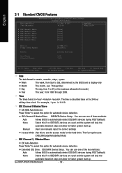
... Defaults Date The date format is calculated base on the 24-hour military-time clock. Through Dec The day, from 1999 through 2099. For example, 1 p.m. GA-945P-DS3/S3 Motherboard - 32 - is display-only Month Day The month, Jan. Manual User can use one of three methods: Auto Allows BIOS to automatically detect IDE...
... Defaults Date The date format is calculated base on the 24-hour military-time clock. Through Dec The day, from 1999 through 2099. For example, 1 p.m. GA-945P-DS3/S3 Motherboard - 32 - is display-only Month Day The month, Jan. Manual User can use one of three methods: Auto Allows BIOS to automatically detect IDE...
Manual
Page 34
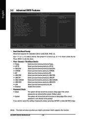
... Select boot sequence for onboard(or add-on cards) SCSI, RAID, etc. First / Second / Third Boot Device Floppy Select your boot device priority by Floppy. GA-945P-DS3/S3 Motherboard - 34 - Password Check Setup The system will boot but will not access to Setup page if the correct password is not entered at the...
... Select boot sequence for onboard(or add-on cards) SCSI, RAID, etc. First / Second / Third Boot Device Floppy Select your boot device priority by Floppy. GA-945P-DS3/S3 Motherboard - 34 - Password Check Setup The system will boot but will not access to Setup page if the correct password is not entered at the...
Manual
Page 36
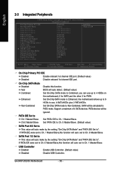
... make by the setting "On-Chip SATA Mode" and "PATA IDE Set to PATA mode. SATA Port 1/3 Set to This value will be simulated to ". GA-945P-DS3/S3 Motherboard - 36 -
... make by the setting "On-Chip SATA Mode" and "PATA IDE Set to PATA mode. SATA Port 1/3 Set to This value will be simulated to ". GA-945P-DS3/S3 Motherboard - 36 -
Manual
Page 38
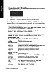
... port and address is 278/IRQ5. 3BC/IRQ7 Enable onboard LPT port and address is 2E8/IRQ3. Note: The Gigabit hub will operate at Port..... GA-945P-DS3/S3 Motherboard - 38 - ECP+EPP Using Parallel port as Extended Capabilities Port. Link Detected --> 100Mbps Cable Length= 30m Link Detected Cable Length Displays transmission speed Displays...
... port and address is 278/IRQ5. 3BC/IRQ7 Enable onboard LPT port and address is 2E8/IRQ3. Note: The Gigabit hub will operate at Port..... GA-945P-DS3/S3 Motherboard - 38 - ECP+EPP Using Parallel port as Extended Capabilities Port. Link Detected --> 100Mbps Cable Length= 30m Link Detected Cable Length Displays transmission speed Displays...

