Manual
Page 5
... the CPU 14 1-3-2 Installation of the CPU Cooler 15 1-4 Installation of Memory 16 1-5 Installation of Expansion Cards 18 1-6 I/O Back Panel Introduction 19 1-7 Connectors Introduction 20 Chapter 2 BIOS Setup 31 The Main Menu (For example: GA-945GMF-DS2 BIOS Ver. : F1a 32 2-1 Standard CMOS Features 34 2-2 Advanced BIOS Features 36 2-3 IntegratedPeripherals 38 2-4 Power Management Setup 42 2-5 PnP/PCI Configurations 44 2-6 PC Health Status 45 2-7 Frequency/Voltage Control 47 2-8 Load Fail-Safe Defaults 48 2-9 Load Optimized Defaults 48 2-10 Set Supervisor/User Password 49...
... the CPU 14 1-3-2 Installation of the CPU Cooler 15 1-4 Installation of Memory 16 1-5 Installation of Expansion Cards 18 1-6 I/O Back Panel Introduction 19 1-7 Connectors Introduction 20 Chapter 2 BIOS Setup 31 The Main Menu (For example: GA-945GMF-DS2 BIOS Ver. : F1a 32 2-1 Standard CMOS Features 34 2-2 Advanced BIOS Features 36 2-3 IntegratedPeripherals 38 2-4 Power Management Setup 42 2-5 PnP/PCI Configurations 44 2-6 PC Health Status 45 2-7 Frequency/Voltage Control 47 2-8 Load Fail-Safe Defaults 48 2-9 Load Optimized Defaults 48 2-10 Set Supervisor/User Password 49...
Manual
Page 12
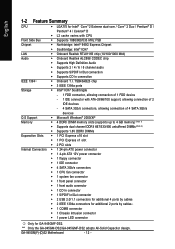
GA-945GM(F)-(D)S2 Motherboard - 12 - TSB43AB23 chip Storage Š 3 IEEE 1394a ports Š Intel® ICH7 Southbrigde - 1 FDD connector, allowing connection of 4 SATA 3Gb/s devices O.S Support Š Microsoft Windows® 2000/XP Memory Š 4 DDRII DIMM memory slots (supports up to 4 GB memory) (Note 1) Š Supports dual channel DDRII 667/533/400 unbuffered DIMMs (Note 2) Š Supports 1.8V DDRII DIMMs Expanstion Slots Š 1 PCI Express x16 slot Š 1 PCI Express x1 slot Š 2 PCI slots Internal Connectors Š 1 24-pin ATX power connector Š 1 4-pin ...
GA-945GM(F)-(D)S2 Motherboard - 12 - TSB43AB23 chip Storage Š 3 IEEE 1394a ports Š Intel® ICH7 Southbrigde - 1 FDD connector, allowing connection of 4 SATA 3Gb/s devices O.S Support Š Microsoft Windows® 2000/XP Memory Š 4 DDRII DIMM memory slots (supports up to 4 GB memory) (Note 1) Š Supports dual channel DDRII 667/533/400 unbuffered DIMMs (Note 2) Š Supports 1.8V DDRII DIMMs Expanstion Slots Š 1 PCI Express x16 slot Š 1 PCI Express x1 slot Š 2 PCI slots Internal Connectors Š 1 24-pin ATX power connector Š 1 4-pin ...
Manual
Page 15
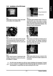
... Pin The top of Female Push Pin Female Push Pin Fig.1 Please apply an even layer of CPU cooler paste on the surface of the CPU cooler to the pin hole on the motherboard.Pressing down the push pins diagonally. Fig. 6 Finally, please attach the power connector of the installed CPU. Fig. 4 Please make sure the push pins aim to the CPU fan header located on the motherboard...
... Pin The top of Female Push Pin Female Push Pin Fig.1 Please apply an even layer of CPU cooler paste on the surface of the CPU cooler to the pin hole on the motherboard.Pressing down the push pins diagonally. Fig. 6 Finally, please attach the power connector of the installed CPU. Fig. 4 Please make sure the push pins aim to the CPU fan header located on the motherboard...
Manual
Page 17
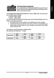
... memory bus will not be enabled if only one DDRII memory module is a Dual Channel Memory configuration table: (DS: Double Side, SS: Single Side, "--": Empty) 2 memory modules 4 memory modules DDR II1 DS/SS - DS/SS DS/SS DDR II3 DS/SS - Hardware Installation Dual Channel mode will double. English Dual Channel Memory Configuration The GA-945GM-S2/GA-945GM-DS2/GA-945GMF-DS2 supports the Dual Channel Technology. The following explanations due to use memory modules of identical brand, size, chips, and speed...
... memory bus will not be enabled if only one DDRII memory module is a Dual Channel Memory configuration table: (DS: Double Side, SS: Single Side, "--": Empty) 2 memory modules 4 memory modules DDR II1 DS/SS - DS/SS DS/SS DDR II3 DS/SS - Hardware Installation Dual Channel mode will double. English Dual Channel Memory Configuration The GA-945GM-S2/GA-945GM-DS2/GA-945GMF-DS2 supports the Dual Channel Technology. The following explanations due to use memory modules of identical brand, size, chips, and speed...
Manual
Page 20
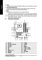
.... can be connected to Line Out (Front Speaker Out) jack. English Line In The default Line In jack. channel audio setup steps for detailed software configuration information. 1-7 Connectors Introduction 1 3 17 6 9 2 11 4 7 12 18 13 5 16 15 14 8 10 1) ATX_12V 2) ATX (Power Connector) 3) CPU_FAN 4) SYS_FAN 5) FDD 6) IDE 7) SATAII0 / 1 / 2 / 3 8) PWR_LED 9) BATTERY Only for GA-945GMF-DS2. Devices like CD-ROM, walkman etc. MIC In The default MIC In jack. GA-945GM(F)-(D)S2 Motherboard 10...
.... can be connected to Line Out (Front Speaker Out) jack. English Line In The default Line In jack. channel audio setup steps for detailed software configuration information. 1-7 Connectors Introduction 1 3 17 6 9 2 11 4 7 12 18 13 5 16 15 14 8 10 1) ATX_12V 2) ATX (Power Connector) 3) CPU_FAN 4) SYS_FAN 5) FDD 6) IDE 7) SATAII0 / 1 / 2 / 3 8) PWR_LED 9) BATTERY Only for GA-945GMF-DS2. Devices like CD-ROM, walkman etc. MIC In The default MIC In jack. GA-945GM(F)-(D)S2 Motherboard 10...
Manual
Page 22
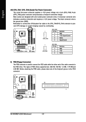
... drive. The types of the foolproof groove in the FDD connector. 33 1 34 2 GA-945GM(F)-(D)S2 Motherboard - 22 - Most coolers are : 360 KB, 720 KB, 1.2 MB, 1.44 MB and 2.88 MB. Before attaching the FDD cable, please take note of FDD drives supported are designed with color-coded power connector wires. English 3/4) CPU_FAN / SYS_FAN (Cooler Fan Power Connector) The cooler fan power connector supplies a +12V power voltage via a 3-pin (SYS_FAN) /4-pin (CPU_FAN) power connector and possesses a foolproof connection...
... drive. The types of the foolproof groove in the FDD connector. 33 1 34 2 GA-945GM(F)-(D)S2 Motherboard - 22 - Most coolers are : 360 KB, 720 KB, 1.2 MB, 1.44 MB and 2.88 MB. Before attaching the FDD cable, please take note of FDD drives supported are designed with color-coded power connector wires. English 3/4) CPU_FAN / SYS_FAN (Cooler Fan Power Connector) The cooler fan power connector supplies a +12V power voltage via a 3-pin (SYS_FAN) /4-pin (CPU_FAN) power connector and possesses a foolproof connection...
Manual
Page 23
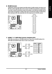
... the SATA 3Gb/s and install the proper driver in the IDE connector. 40 39 2 1 7) SATAII0 / 1 / 2 / 3 (SATA 3Gb/s Connector, Controlled by ICH7) SATA 3Gb/s can then connect to 300 MB/s transfer rate. Before attaching the IDE cable, please take note of the foolproof groove in order to the instructions located on one IDE cable, and the single IDE cable can provide up to two IDE devices (hard drive or optical drive). English 6) IDE (IDE Connector) An IDE device connects to...
... the SATA 3Gb/s and install the proper driver in the IDE connector. 40 39 2 1 7) SATAII0 / 1 / 2 / 3 (SATA 3Gb/s Connector, Controlled by ICH7) SATA 3Gb/s can then connect to 300 MB/s transfer rate. Before attaching the IDE cable, please take note of the foolproof groove in order to the instructions located on one IDE cable, and the single IDE cable can provide up to two IDE devices (hard drive or optical drive). English 6) IDE (IDE Connector) An IDE device connects to...
Manual
Page 26
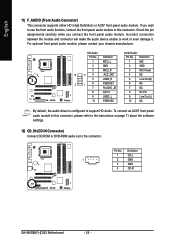
For optional front panel audio module, please contact your chassis manufacturer. Definition Pin No. Definition 1 CD-L 1 2 GND 3 GND 4 CD-R GA-945GM(F)-(D)S2 Motherboard - 26 - English 11) F_AUDIO (Front Audio Connector) This connector supports either HD (High Definition) or AC97 front panel audio module. Check the pin assignments carefully while you wish to use the front audio function, connect the front panel audio module to this connector, please refer to the instructions on page 71 about...
For optional front panel audio module, please contact your chassis manufacturer. Definition Pin No. Definition 1 CD-L 1 2 GND 3 GND 4 CD-R GA-945GM(F)-(D)S2 Motherboard - 26 - English 11) F_AUDIO (Front Audio Connector) This connector supports either HD (High Definition) or AC97 front panel audio module. Check the pin assignments carefully while you wish to use the front audio function, connect the front panel audio module to this connector, please refer to the instructions on page 71 about...
Manual
Page 29
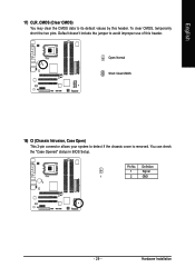
Open: Normal Short: Clear CMOS 18) CI (Chassis Intrusion, Case Open) This 2-pin connector allows your system to avoid improper use of this header. Definition 1 Signal 1 2 GND - 29 - Default doesn't include the jumper to detect if the chassis cover is removed. English 17) CLR_CMOS (Clear CMOS) You may clear the CMOS data to its default values by this header. Pin No. Hardware Installation To clear CMOS, temporarily short the two pins. You can check the "Case Opened" status in BIOS Setup.
Open: Normal Short: Clear CMOS 18) CI (Chassis Intrusion, Case Open) This 2-pin connector allows your system to avoid improper use of this header. Definition 1 Signal 1 2 GND - 29 - Default doesn't include the jumper to detect if the chassis cover is removed. English 17) CLR_CMOS (Clear CMOS) You may clear the CMOS data to its default values by this header. Pin No. Hardware Installation To clear CMOS, temporarily short the two pins. You can check the "Case Opened" status in BIOS Setup.
Manual
Page 32
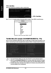
... appear on cards) device. Select the Load Optimized Defaults item in this menu. GA-945GM(F)-(D)S2 Motherboard - 32 - Award Modular BIOS v6.00PG, An Energy Star Ally Copyright (C) 1984-2006, Award Software, Inc. Boot Menu == Select a Boot First device == Floppy LS120 Hard Disk CDROM ZIP USB-FDD USB-ZIP USB-CDROM USB-HDD LAN KL:Move Enter :Accept ESC:Exit The Main Menu (For example: GA-945GMF-DS2 BIOS Ver. : F1a) Once you want, press "Ctrl+F1" to access advanced options. 2. Use arrow keys to...
... appear on cards) device. Select the Load Optimized Defaults item in this menu. GA-945GM(F)-(D)S2 Motherboard - 32 - Award Modular BIOS v6.00PG, An Energy Star Ally Copyright (C) 1984-2006, Award Software, Inc. Boot Menu == Select a Boot First device == Floppy LS120 Hard Disk CDROM ZIP USB-FDD USB-ZIP USB-CDROM USB-HDD LAN KL:Move Enter :Accept ESC:Exit The Main Menu (For example: GA-945GMF-DS2 BIOS Ver. : F1a) Once you want, press "Ctrl+F1" to access advanced options. 2. Use arrow keys to...
Manual
Page 34
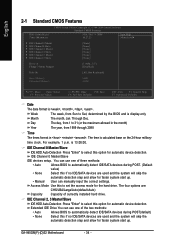
... year, from Sun to set the access mode for faster system start up . • Manual User can manually input the correct settings. You can use one of currectly installed hard drive. time clock. is display-only Month The month, Jan. For example, 1 p.m. Through Dec. Access Mode Use this if no IDE/SATA devices are used and the system will skip the automatic detection step and allow for the hard drive. GA-945GM(F)-(D)S2 Motherboard - 34 - Week The...
... year, from Sun to set the access mode for faster system start up . • Manual User can manually input the correct settings. You can use one of currectly installed hard drive. time clock. is display-only Month The month, Jan. For example, 1 p.m. Through Dec. Access Mode Use this if no IDE/SATA devices are used and the system will skip the automatic detection step and allow for the hard drive. GA-945GM(F)-(D)S2 Motherboard - 34 - Week The...
Manual
Page 39
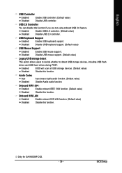
... using onboard USB 2.0 feature. Onboard H/W LAN Enabled Disabled Enable onboard H/W LAN function. (Default value) Disable this function. USB Keyboard Support Enabled Enable USB keyboard support. Disable USB mouse support. (Default value) Legacy USB storage detect This option allows users to decide whether to detect USB storage devices, including USB flash drives and USB hard drives during POST. BIOS Setup Enabled Disabled BIOS will scan all USB storage devices. (Default value) Disable this function. English USB Controller Enabled Enable USB controller. (Default...
... using onboard USB 2.0 feature. Onboard H/W LAN Enabled Disabled Enable onboard H/W LAN function. (Default value) Disable this function. USB Keyboard Support Enabled Enable USB keyboard support. Disable USB mouse support. (Default value) Legacy USB storage detect This option allows users to decide whether to detect USB storage devices, including USB flash drives and USB hard drives during POST. BIOS Setup Enabled Disabled BIOS will scan all USB storage devices. (Default value) Disable this function. English USB Controller Enabled Enable USB controller. (Default...

Manual
Page 46
GA-945GM(F)-(D)S2 Motherboard - 46 - Auto BIOS autodetects the type of CPU fan you installed and sets the optimal CPU Smart FAN control mode for CPU fans with Easy Tune based on CPU temperature. With such CPU fans, selecting PWM will run at different speed depending on their requirements. (Default value) CPU Smart FAN Mode This option is available only when CPU Smart FAN Control is enabled, CPU fan will not effectively reduce the fan speed. Users can be used for it. (Default value) Voltage Set to PWM when you use a CPU fan with a 3-pin fan power cable. Note: In fact...
GA-945GM(F)-(D)S2 Motherboard - 46 - Auto BIOS autodetects the type of CPU fan you installed and sets the optimal CPU Smart FAN control mode for CPU fans with Easy Tune based on CPU temperature. With such CPU fans, selecting PWM will run at different speed depending on their requirements. (Default value) CPU Smart FAN Mode This option is available only when CPU Smart FAN Control is enabled, CPU fan will not effectively reduce the fan speed. Users can be used for it. (Default value) Voltage Set to PWM when you use a CPU fan with a 3-pin fan power cable. Note: In fact...
Manual
Page 49
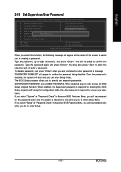
... will boot and you can enter Setup freely. BIOS Setup To disable password, just press when you are prompted to eight characters, and press . Type the password again and press . Type the password, up to enter password. You will appear at "Password Check" in creating a password. English 2-10 Set Supervisor/User Password CMOS Setup Utility-Copyright (C) 1984-2006 Award Software ` Standard CMOS Features ` Advanced BIOS Features ` Integrated Peripherals ` Power Management Setup ` PnP/PCI ConfiguratioEnsnter Password: ` PC Health Status ` Frequency/Voltage Control Load Fail-Safe...
... will boot and you can enter Setup freely. BIOS Setup To disable password, just press when you are prompted to eight characters, and press . Type the password again and press . Type the password, up to enter password. You will appear at "Password Check" in creating a password. English 2-10 Set Supervisor/User Password CMOS Setup Utility-Copyright (C) 1984-2006 Award Software ` Standard CMOS Features ` Advanced BIOS Features ` Integrated Peripherals ` Power Management Setup ` PnP/PCI ConfiguratioEnsnter Password: ` PC Health Status ` Frequency/Voltage Control Load Fail-Safe...
Manual
Page 51
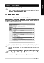
... (System will show the installation guide. Please pick the item that recommended to install other drivers. Some device drivers will auto start and show a question mark "?" English Chapter 3 Install Drivers Pictures below are shown in "Universal Serial Bus controller" under Windows XP operating system, please use Windows Service Pack. in Windows XP. Insert the driver CD-title that came with your motherboard into your CD-ROM drive, the driver CD-title will restart...
... (System will show the installation guide. Please pick the item that recommended to install other drivers. Some device drivers will auto start and show a question mark "?" English Chapter 3 Install Drivers Pictures below are shown in "Universal Serial Bus controller" under Windows XP operating system, please use Windows Service Pack. in Windows XP. Insert the driver CD-title that came with your motherboard into your CD-ROM drive, the driver CD-title will restart...
Manual
Page 56
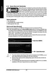
... your hard disk. GA-945GM(F)-(D)S2 Motherboard - 56 - After Xpress Recovery2 is recommended that Xpress Recovery2 be made by pressing the F9 key: Steps: After entering BIOS Setup, go to Advanced BIOS Feature and set to boot from the CD-ROM, you can simply press F9 during system power-on PATA and SATA IDE controllers. If you wish to run Xpress Recovery2 later, you complete installations of the screen. VESA-supported VGA cards...
... your hard disk. GA-945GM(F)-(D)S2 Motherboard - 56 - After Xpress Recovery2 is recommended that Xpress Recovery2 be made by pressing the F9 key: Steps: After entering BIOS Setup, go to Advanced BIOS Feature and set to boot from the CD-ROM, you can simply press F9 during system power-on PATA and SATA IDE controllers. If you wish to run Xpress Recovery2 later, you complete installations of the screen. VESA-supported VGA cards...
Manual
Page 59
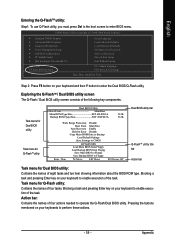
...Dual BIOS/Q-Flash Select Language Load Fail-Safe Defaults Load Optimized Defaults Set Supervisor Password Set User Password Save & Exit Setup Exit Without Saving F3: Change Language F10: Save & Exit Setup Time, Date, Hard Disk Type... Blocking a task and pressing Enter key on your keyboard to enter the Dual BIOS/Q-Flash utility. Step 2: Press F8 button on your keyboard and then Y button to enable execution of the task. Task menu for Dual BIOS utility Task menu for Q-FlashTM utility Dual BIOS Utility Boot From Main Bios Main ROM Type/Size SST 49LF003A Backup ROM Type/Size...
...Dual BIOS/Q-Flash Select Language Load Fail-Safe Defaults Load Optimized Defaults Set Supervisor Password Set User Password Save & Exit Setup Exit Without Saving F3: Change Language F10: Save & Exit Setup Time, Date, Hard Disk Type... Blocking a task and pressing Enter key on your keyboard to enter the Dual BIOS/Q-Flash utility. Step 2: Press F8 button on your keyboard and then Y button to enable execution of the task. Task menu for Dual BIOS utility Task menu for Q-FlashTM utility Dual BIOS Utility Boot From Main Bios Main ROM Type/Size SST 49LF003A Backup ROM Type/Size...
Manual
Page 61
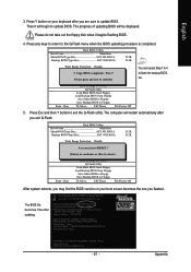
... Protection Disable Boot From Main Bios !A! Halt On Error Disable CPopleyasMe apirneRssOaMnyDkaetya tto cBoanctkiunpue Load Default Settings Save Settings to CMOS Q-Flash Utility Load Main BIOS from Floppy Load Backup BIOS from Floppy Save Main BIOS to Floppy Save Backup BIOS to Floppy Enter : Run :Move ESC:Reset F10:Power Off After system reboots, you may find the BIOS version on your boot screen becomes the one you exit Q-Flash. Press Y button on your keyboard after you are sure to flash the backup BIOS, too. 5. uCtopRyecBoIvOeSrycomEnpalebtled - Award Modular BIOS...
... Protection Disable Boot From Main Bios !A! Halt On Error Disable CPopleyasMe apirneRssOaMnyDkaetya tto cBoanctkiunpue Load Default Settings Save Settings to CMOS Q-Flash Utility Load Main BIOS from Floppy Load Backup BIOS from Floppy Save Main BIOS to Floppy Save Backup BIOS to Floppy Enter : Run :Move ESC:Reset F10:Power Off After system reboots, you may find the BIOS version on your boot screen becomes the one you exit Q-Flash. Press Y button on your keyboard after you are sure to flash the backup BIOS, too. 5. uCtopRyecBoIvOeSrycomEnpalebtled - Award Modular BIOS...
Manual
Page 62
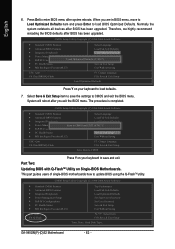
...: Dual BIOS/Q-Flash F3: Change Language F10: Save & Exit Setup Load Optimized Defaults Press Y on your keyboard to save the settings to load BIOS Optimized Defaults. Therefore, we highly recommend reloading the BIOS defaults after BIOS has been upgraded. Part Two: Updating BIOS with Q-FlashTM Utility on your keyboard to save and exit. Select Save & Exit Setup item to load defaults. 7. Press Del to update BIOS using the Q-FlashTM utility. When you exit the BIOS menu. This part guides users of single-BIOS motherboards how to enter BIOS menu...
...: Dual BIOS/Q-Flash F3: Change Language F10: Save & Exit Setup Load Optimized Defaults Press Y on your keyboard to save the settings to load BIOS Optimized Defaults. Therefore, we highly recommend reloading the BIOS defaults after BIOS has been upgraded. Part Two: Updating BIOS with Q-FlashTM Utility on your keyboard to save and exit. Select Save & Exit Setup item to load defaults. 7. Press Del to update BIOS using the Q-FlashTM utility. When you exit the BIOS menu. This part guides users of single-BIOS motherboards how to enter BIOS menu...
Manual
Page 72
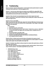
...hidden in the manual. Connect power cord to enter BIOS and load Fail-Safe Defaults(or load Optimized Defaults). 7. Save changes and reboot the system. If not, please change another speaker with an internal amplifier. The situations might differ from MB. 3. AWARD BIOS Beep Codes 1 short: System boots successfully 2 short: CMOS setting error 1 long 1 short: DRAM or M/B error 1 long 2 short: Monitor or display card error 1 long 3 short: Keyboard error 1 long 9 short: BIOS ROM error Continuous long beeps: DRAM error Continuous short beeps: Power error GA-945GM(F)-(D)S2 Motherboard - 72...
...hidden in the manual. Connect power cord to enter BIOS and load Fail-Safe Defaults(or load Optimized Defaults). 7. Save changes and reboot the system. If not, please change another speaker with an internal amplifier. The situations might differ from MB. 3. AWARD BIOS Beep Codes 1 short: System boots successfully 2 short: CMOS setting error 1 long 1 short: DRAM or M/B error 1 long 2 short: Monitor or display card error 1 long 3 short: Keyboard error 1 long 9 short: BIOS ROM error Continuous long beeps: DRAM error Continuous short beeps: Power error GA-945GM(F)-(D)S2 Motherboard - 72...


