Manual
Page 1
GA-945GCM-S2 GA-945GCMX-S2 Intel® CoreTM 2 Extreme dual-core / CoreTM 2 Duo / Intel® Pentium® D / Pentium® 4 / Celeron® D LGA775 Processor Motherboard User's Manual Rev. 6602 12ME-945CMX2R-6602R * The WEEE marking on the product indicates this product must not be disposed of with user's other household waste and must be handed over to a designated collection point for the recycling of waste electrical and electronic equipment!! * The WEEE marking applies only in European Union's member states.
GA-945GCM-S2 GA-945GCMX-S2 Intel® CoreTM 2 Extreme dual-core / CoreTM 2 Duo / Intel® Pentium® D / Pentium® 4 / Celeron® D LGA775 Processor Motherboard User's Manual Rev. 6602 12ME-945CMX2R-6602R * The WEEE marking on the product indicates this product must not be disposed of with user's other household waste and must be handed over to a designated collection point for the recycling of waste electrical and electronic equipment!! * The WEEE marking applies only in European Union's member states.
Manual
Page 3
Motherboard GA-945GCM-S2 Jan. 12, 2007 Motherboard GA-945GCM-S2 Jan. 12, 2007
Motherboard GA-945GCM-S2 Jan. 12, 2007 Motherboard GA-945GCM-S2 Jan. 12, 2007
Manual
Page 5
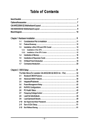
Table of Contents ItemChecklist ...7 OptionalAccessories ...7 GA-945GCMX-S2 Motherboard Layout 8 GA-945GCM-S2 Motherboard Layout 9 Block Diagram ...10 Chapter 1 Hardware Installation 11 1-1 Considerations Prior to Installation 11 1-2 Feature Summary 12...1-5 Installation of Expansion Cards 18 1-6 I/O Back Panel Introduction 19 1-7 Connectors Introduction 20 Chapter 2 BIOS Setup 31 The Main Menu (For example: GA-945GCMX-S2 BIOS Ver. : F5a 32 2-1 Standard CMOS Features 34 2-2 Advanced BIOS Features 36 2-3 IntegratedPeripherals 38 2-4 Power Management Setup 42 2-5 PnP/PCI ...
Table of Contents ItemChecklist ...7 OptionalAccessories ...7 GA-945GCMX-S2 Motherboard Layout 8 GA-945GCM-S2 Motherboard Layout 9 Block Diagram ...10 Chapter 1 Hardware Installation 11 1-1 Considerations Prior to Installation 11 1-2 Feature Summary 12...1-5 Installation of Expansion Cards 18 1-6 I/O Back Panel Introduction 19 1-7 Connectors Introduction 20 Chapter 2 BIOS Setup 31 The Main Menu (For example: GA-945GCMX-S2 BIOS Ver. : F5a 32 2-1 Standard CMOS Features 34 2-2 Advanced BIOS Features 36 2-3 IntegratedPeripherals 38 2-4 Power Management Setup 42 2-5 PnP/PCI ...
Manual
Page 9
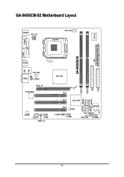
GA-945GCM-S2 Motherboard Layout KB_MS ATX_12V CPU_FAN LGA775 IT8718 COMA LPT VGA GA-945GCM-S2 ATX R_USB LAN USB AUDIO SYS_FAN F_AUDIO PCIE_16 RTL8110SC CODEC CD_IN COMB SPDIF_IO Intel® 945 DDRII1 DDRII2 IDE FDD PCI1 SATAII0 SATAII2 SATAII1 SATAII3 PCI2 Intel® ICH7 PCI3 BIOS F_USB1 F_USB2 BATTERY CLR_CMOS CI PWR_LED F_PANEL - 9 -
GA-945GCM-S2 Motherboard Layout KB_MS ATX_12V CPU_FAN LGA775 IT8718 COMA LPT VGA GA-945GCM-S2 ATX R_USB LAN USB AUDIO SYS_FAN F_AUDIO PCIE_16 RTL8110SC CODEC CD_IN COMB SPDIF_IO Intel® 945 DDRII1 DDRII2 IDE FDD PCI1 SATAII0 SATAII2 SATAII1 SATAII3 PCI2 Intel® ICH7 PCI3 BIOS F_USB1 F_USB2 BATTERY CLR_CMOS CI PWR_LED F_PANEL - 9 -
Manual
Page 10
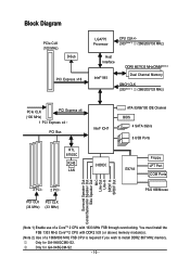
You must install the FSB 1333 MHz CoreTM 2 CPU with 1333 MHz FSB through overclocking. Only for GA-945GCM-S2. - 10 - Only for GA-945GCMX-S2. Block Diagram PCIe CLK (100 MHz) D-Sub PCI Express x16 LGA775 Processor CPU CLK+/(333(Note 1) /266/200/133 MHz) Host Interface DDRII 667/533 ...
You must install the FSB 1333 MHz CoreTM 2 CPU with 1333 MHz FSB through overclocking. Only for GA-945GCM-S2. - 10 - Only for GA-945GCMX-S2. Block Diagram PCIe CLK (100 MHz) D-Sub PCI Express x16 LGA775 Processor CPU CLK+/(333(Note 1) /266/200/133 MHz) Host Interface DDRII 667/533 ...
Manual
Page 12
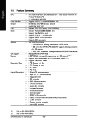
GA-945GCM(X)-S2 Motherboard - 12 - English 1-2 Feature Summary CPU Š LGA775 for Intel® CoreTM 2 Extreme dual-core / CoreTM 2 Duo / Pentium® D / Pentium® 4 / Celeron® D Š L2 ...; 1 S/PDIF In/Out connector Š 2 USB 2.0/1.1 connectors for additional 4 ports by cables Š 1 COMB connector Š 1 Chassis Intrusion connector Š 1 power LED connector Only for GA-945GCM-S2. Only for GA-945GCMX-S2.
GA-945GCM(X)-S2 Motherboard - 12 - English 1-2 Feature Summary CPU Š LGA775 for Intel® CoreTM 2 Extreme dual-core / CoreTM 2 Duo / Pentium® D / Pentium® 4 / Celeron® D Š L2 ...; 1 S/PDIF In/Out connector Š 2 USB 2.0/1.1 connectors for additional 4 ports by cables Š 1 COMB connector Š 1 Chassis Intrusion connector Š 1 power LED connector Only for GA-945GCM-S2. Only for GA-945GCMX-S2.
Manual
Page 14
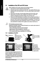
... install the CPU in accordance with HT Technology - Fig. 3 Notice the small gold colored triangle located on the CPU prior to the CPU during installation.) GA-945GCM(X)-S2 Motherboard - 14 - Avoid twisting or bending motions that supports HT Technology - Chipset: An Intel® Chipset that might cause damage to system use, otherwise overheating...
... install the CPU in accordance with HT Technology - Fig. 3 Notice the small gold colored triangle located on the CPU prior to the CPU during installation.) GA-945GCM(X)-S2 Motherboard - 14 - Avoid twisting or bending motions that supports HT Technology - Chipset: An Intel® Chipset that might cause damage to system use, otherwise overheating...
Manual
Page 16
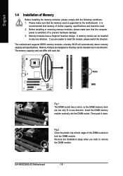
... memory used is recommended that they can differ with the following conditions: 1. A memory module can only fit in only one direction. Then push it down. GA-945GCM(X)-S2 Motherboard - 16 - Memory modules have a foolproof insertion design. Before installing or removing memory modules, please make sure that the computer power is switched off to...
... memory used is recommended that they can differ with the following conditions: 1. A memory module can only fit in only one direction. Then push it down. GA-945GCM(X)-S2 Motherboard - 16 - Memory modules have a foolproof insertion design. Before installing or removing memory modules, please make sure that the computer power is switched off to...

Manual
Page 17
After operating the Dual Channel Technology, the bandwidth of memory bus will not be used. - 17 - The GA-945GCMX-S2/GA-945GCM-S2 includes 2 DIMM sockets. If you want to operate the Dual Channel Technology, please note the following explanations due to the limitation of the same capacity, ... enabling Dual Channel mode with two memory modules, it is recommended that memory of Intel chipset specifications. 1. Hardware Installation English Dual Channel Memory Configuration The GA-945GCMX-S2/GA-945GCM-S2 supports the Dual Channel Technology.
After operating the Dual Channel Technology, the bandwidth of memory bus will not be used. - 17 - The GA-945GCMX-S2/GA-945GCM-S2 includes 2 DIMM sockets. If you want to operate the Dual Channel Technology, please note the following explanations due to the limitation of the same capacity, ... enabling Dual Channel mode with two memory modules, it is recommended that memory of Intel chipset specifications. 1. Hardware Installation English Dual Channel Memory Configuration The GA-945GCMX-S2/GA-945GCM-S2 supports the Dual Channel Technology.
Manual
Page 18
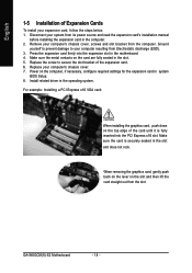
.... 2. Replace the screw to your computer resulting from the computer. Make sure the card is fully inserted into the expansion slot in the operating system. GA-945GCM(X)-S2 Motherboard - 18 - For example: Installing a PCI Express x16 VGA card: When installing the graphics card, push down on the card are fully seated in system...
.... 2. Replace the screw to your computer resulting from the computer. Make sure the card is fully inserted into the expansion slot in the operating system. GA-945GCM(X)-S2 Motherboard - 18 - For example: Installing a PCI Express x16 VGA card: When installing the graphics card, push down on the card are fully seated in system...

Manual
Page 20
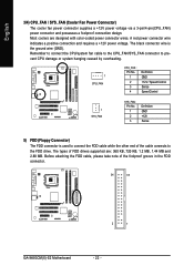
... Connector) 3) CPU_FAN 4) SYS_FAN 5) FDD 6) IDE 7) SATAII0 / 1 / 2 / 3 8) PWR_LED 9) BATTERY 10) F_PANEL 11) F_AUDIO 12) CD_IN 13) SPDIF_IO 14) F_USB1 / F_USB2 15) COMB 16) CLR_CMOS 17) CI GA-945GCM(X)-S2 Motherboard - 20 - Microphone must be connected to MIC In jack.
... Connector) 3) CPU_FAN 4) SYS_FAN 5) FDD 6) IDE 7) SATAII0 / 1 / 2 / 3 8) PWR_LED 9) BATTERY 10) F_PANEL 11) F_AUDIO 12) CD_IN 13) SPDIF_IO 14) F_USB1 / F_USB2 15) COMB 16) CLR_CMOS 17) CI GA-945GCM(X)-S2 Motherboard - 20 - Microphone must be connected to MIC In jack.
Manual
Page 22
... cable while the other end of the cable connects to the FDD drive. The types of the foolproof groove in the FDD connector. 34 33 2 1 GA-945GCM(X)-S2 Motherboard - 22 - Before attaching the FDD cable, please take note of FDD drives supported are designed with color-coded power connector wires. Remember to connect...
... cable while the other end of the cable connects to the FDD drive. The types of the foolproof groove in the FDD connector. 34 33 2 1 GA-945GCM(X)-S2 Motherboard - 22 - Before attaching the FDD cable, please take note of FDD drives supported are designed with color-coded power connector wires. Remember to connect...
Manual
Page 24
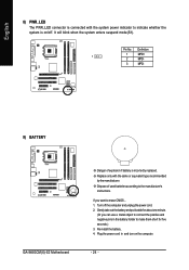
... explosion if battery is on the computer. - 24 - If you can use a metal object to the manufacturer's instructions. Pin No. Definition 1 1 MPD+ 2 MPD- 3 MPD- 9) BATTERY GA-945GCM(X)-S2 Motherboard Danger of used batteries according to connect the positive and negative pins in and turn on /off the computer and unplug the power cord. 2.
... explosion if battery is on the computer. - 24 - If you can use a metal object to the manufacturer's instructions. Pin No. Definition 1 1 MPD+ 2 MPD- 3 MPD- 9) BATTERY GA-945GCM(X)-S2 Motherboard Danger of used batteries according to connect the positive and negative pins in and turn on /off the computer and unplug the power cord. 2.
Manual
Page 26
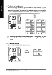
Incorrect connection between the module and connector will make the audio device unable to support HD Audio. Definition 1 CD-L 1 2 GND 3 GND 4 CD-R GA-945GCM(X)-S2 Motherboard - 26 - If you connect the front panel audio module. Definition 1 MIC 2 GND 3 MIC Power 4 NC 5 Line Out (R) 6 NC 7 NC 8 No Pin 9 Line Out (L) 10 ...
Incorrect connection between the module and connector will make the audio device unable to support HD Audio. Definition 1 CD-L 1 2 GND 3 GND 4 CD-R GA-945GCM(X)-S2 Motherboard - 26 - If you connect the front panel audio module. Definition 1 MIC 2 GND 3 MIC Power 4 NC 5 Line Out (R) 6 NC 7 NC 8 No Pin 9 Line Out (L) 10 ...
Manual
Page 28
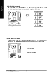
... (COMB Connector) Be careful with the polarity of this header. Check the pin assignments while you connect the COMB cable. Open: Normal Short: Clear CMOS GA-945GCM(X)-S2 Motherboard - 28 - Please contact your nearest dealer for optional COMB cable. 9 1 10 2 Pin No. 1 2 3 4 5 6 7 8 9 10 Definition NDCDBNSINB NSOUTB NDTRBGND NDSRBNRTSBNCTSBNRIBNo Pin 16) CLR_CMOS (Clear CMOS...
... (COMB Connector) Be careful with the polarity of this header. Check the pin assignments while you connect the COMB cable. Open: Normal Short: Clear CMOS GA-945GCM(X)-S2 Motherboard - 28 - Please contact your nearest dealer for optional COMB cable. 9 1 10 2 Pin No. 1 2 3 4 5 6 7 8 9 10 Definition NDCDBNSINB NSOUTB NDTRBGND NDSRBNRTSBNCTSBNRIBNo Pin 16) CLR_CMOS (Clear CMOS...

Manual
Page 30
English GA-945GCM(X)-S2 Motherboard - 30 -
English GA-945GCM(X)-S2 Motherboard - 30 -

Manual
Page 32
English : Boot Menu Select boot sequence for 945GCMX-S2 F5a . . . . :BIOS Setup/Q-Flash :XpressRecovery2 :Boot Menu :Qflash 05/25/2007-I945-6A79TG0OC-00 : For Boot Menu Use < > or < > to select a device, then press enter ...-FDD USB-ZIP USB-CDROM USB-HDD LAN KL:Move Enter :Accept ESC:Exit The Main Menu (For example: GA-945GCMX-S2 BIOS Ver. : F5a) Once you want, press "Ctrl+F1" to access advanced options. 2. GA-945GCM(X)-S2 Motherboard - 32 - This action makes the system reset to exit this chapter are for reference only and may...
English : Boot Menu Select boot sequence for 945GCMX-S2 F5a . . . . :BIOS Setup/Q-Flash :XpressRecovery2 :Boot Menu :Qflash 05/25/2007-I945-6A79TG0OC-00 : For Boot Menu Use < > or < > to select a device, then press enter ...-FDD USB-ZIP USB-CDROM USB-HDD LAN KL:Move Enter :Accept ESC:Exit The Main Menu (For example: GA-945GCMX-S2 BIOS Ver. : F5a) Once you want, press "Ctrl+F1" to access advanced options. 2. GA-945GCM(X)-S2 Motherboard - 32 - This action makes the system reset to exit this chapter are for reference only and may...
Manual
Page 34
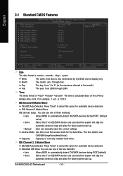
... options are used and the system will skip the automatic detection step and allow for faster system start up . The time is 13:0:0. For example, 1 p.m. GA-945GCM(X)-S2 Motherboard - 34 - You can use one of currectly installed hard drive. IDE Channel 0 Master/Slave IDE devices setup. IDE Channel 2, 3 Master/Slave IDE HDD Auto...
... options are used and the system will skip the automatic detection step and allow for faster system start up . The time is 13:0:0. For example, 1 p.m. GA-945GCM(X)-S2 Motherboard - 34 - You can use one of currectly installed hard drive. IDE Channel 0 Master/Slave IDE devices setup. IDE Channel 2, 3 Master/Slave IDE HDD Auto...
Manual
Page 36
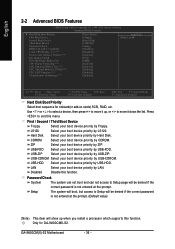
...) This item will be denied if the correct password is not entered at the prompt. Only for onboard(or add-on cards) SCSI, RAID, etc. GA-945GCM(X)-S2 Motherboard - 36 - Use < > or < > to select a device, then press to 3 (Note) No-Execute Memory Protect (Note) Init Display... F10: Save F6: Fail-Safe Defaults ESC: Exit F1: General Help F7: Optimized Defaults Hard Disk Boot Priority Select boot sequence for GA-945GCMX-S2. Select your boot device priority by USB-ZIP. Disabled Disable this menu. English 2-2 Advanced BIOS Features CMOS Setup Utility-Copyright (C) 1984-...
...) This item will be denied if the correct password is not entered at the prompt. Only for onboard(or add-on cards) SCSI, RAID, etc. GA-945GCM(X)-S2 Motherboard - 36 - Use < > or < > to select a device, then press to 3 (Note) No-Execute Memory Protect (Note) Init Display... F10: Save F6: Fail-Safe Defaults ESC: Exit F1: General Help F7: Optimized Defaults Hard Disk Boot Priority Select boot sequence for GA-945GCMX-S2. Select your boot device priority by USB-ZIP. Disabled Disable this menu. English 2-2 Advanced BIOS Features CMOS Setup Utility-Copyright (C) 1984-...
Manual
Page 44
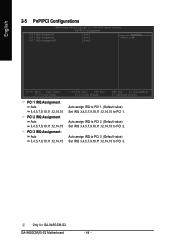
Only for GA-945GCM-S2. GA-945GCM(X)-S2 Motherboard - 44 - Auto assign IRQ to PCI 3. (Default value) Set IRQ 3,4,5,7,9,10,11,12,14,15 to PCI 2. Auto assign IRQ to PCI 2. (Default value) ...
Only for GA-945GCM-S2. GA-945GCM(X)-S2 Motherboard - 44 - Auto assign IRQ to PCI 3. (Default value) Set IRQ 3,4,5,7,9,10,11,12,14,15 to PCI 2. Auto assign IRQ to PCI 2. (Default value) ...


