Manual
Page 1
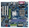
GA-8VM800M-775 Intel® Pentium® 4 LGA775 Processor Motherboard User's Manual Rev. 1002 12ME-VM800MT-1002R * The WEEE marking on the product indicates this product must not be disposed of with user's other household waste and must be handed over to a designated collection point for the recycling of waste electrical and electronic equipment!! * The WEEE marking applies only in European Union's member states.
GA-8VM800M-775 Intel® Pentium® 4 LGA775 Processor Motherboard User's Manual Rev. 1002 12ME-VM800MT-1002R * The WEEE marking on the product indicates this product must not be disposed of with user's other household waste and must be handed over to a designated collection point for the recycling of waste electrical and electronic equipment!! * The WEEE marking applies only in European Union's member states.
Manual
Page 2
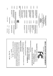
Motherboard GA-8VM800M-775 Aug. 18, 2005 Motherboard GA-8VM800M-775 Aug. 18, 2005
Motherboard GA-8VM800M-775 Aug. 18, 2005 Motherboard GA-8VM800M-775 Aug. 18, 2005
Manual
Page 4
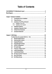
Table of Contents GA-8VM800M-775 Motherboard Layout 6 Block Diagram ...7 Chapter 1 Hardware Installation 9 1-1 Considerations Prior to Installation 9 1-2 Feature Summary 10 1-3 Installation of the CPU and Heatsink 12 1-3-1 Installation of the CPU 12 1-3-2 ...
Table of Contents GA-8VM800M-775 Motherboard Layout 6 Block Diagram ...7 Chapter 1 Hardware Installation 9 1-1 Considerations Prior to Installation 9 1-2 Feature Summary 10 1-3 Installation of the CPU and Heatsink 12 1-3-1 Installation of the CPU 12 1-3-2 ...

Manual
Page 9
... the information in the provided manual. 3. Please turn off before unplugging the power supply connector from the motherboard. If you are connected. 4. Damage as a result of Non-Warranty 1. Damage due to be an unofficial Gigabyte product. - 9 - Product determined to improper installation. 4. English Chapter 1 Hardware Installation 1-1 Considerations Prior to Installation Preparing Your Computer...
... the information in the provided manual. 3. Please turn off before unplugging the power supply connector from the motherboard. If you are connected. 4. Damage as a result of Non-Warranty 1. Damage due to be an unofficial Gigabyte product. - 9 - Product determined to improper installation. 4. English Chapter 1 Hardware Installation 1-1 Considerations Prior to Installation Preparing Your Computer...
Manual
Page 10
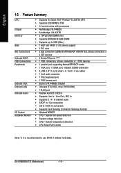
... port Š Built-in VIA P4M800 Chipset Š Onboard RTL8100C chip (10/100 Mbit) Š 1 RJ45 port Š Realtek ALC655 CODEC Š Supports Line In ; GA-8VM800M-775 Motherboard - 10 -
... port Š Built-in VIA P4M800 Chipset Š Onboard RTL8100C chip (10/100 Mbit) Š 1 RJ45 port Š Realtek ALC655 CODEC Š Supports Line In ; GA-8VM800M-775 Motherboard - 10 -
Manual
Page 11
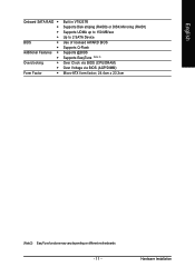
English Onboard SATA RAID Š Š Š Š BIOS Š Š Additional Features Š Š Overclocking Š Š Form Factor Š Built in VT8237R Supports Disk striping (RAID0) or DISK Mirroring (RAID1) Supports UDMA up to 150 MB/sec Up to 2 SATA Device Use of licensed AWARD BIOS Supports Q-Flash Supports @BIOS Supports EasyTune (Note 2) Over Clock via BIOS (CPU/DRAM) Over Voltage via BIOS (AGP/DIMM) Micro-ATX form factor; 24.4cm x 23.3cm (Note 2) EasyTune functions may vary depending on different motherboards. - 11 - Hardware Installation
English Onboard SATA RAID Š Š Š Š BIOS Š Š Additional Features Š Š Overclocking Š Š Form Factor Š Built in VT8237R Supports Disk striping (RAID0) or DISK Mirroring (RAID1) Supports UDMA up to 150 MB/sec Up to 2 SATA Device Use of licensed AWARD BIOS Supports Q-Flash Supports @BIOS Supports EasyTune (Note 2) Over Clock via BIOS (CPU/DRAM) Over Voltage via BIOS (AGP/DIMM) Micro-ATX form factor; 24.4cm x 23.3cm (Note 2) EasyTune functions may vary depending on different motherboards. - 11 - Hardware Installation
Manual
Page 12
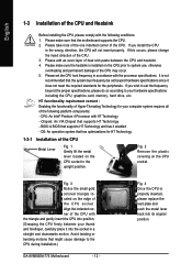
... forefinger, carefully place it enabled - Please make sure the heatsink is installed on the CPU socket to the CPU during installation.) GA-8VM800M-775 Motherboard - 12 - If you wish to system use, otherwise overheating and permanent damage of the CPU may occur. 5. Please add ...1. Chipset: An VIA Chipset that supports HT Technology and has it into its original position. Avoid twisting or bending motions that the motherboard supports the CPU. 2. English 1-3 Installation of the CPU and Heatsink Before installing the CPU, please comply with the following platform components...
... forefinger, carefully place it enabled - Please make sure the heatsink is installed on the CPU socket to the CPU during installation.) GA-8VM800M-775 Motherboard - 12 - If you wish to system use, otherwise overheating and permanent damage of the CPU may occur. 5. Please add ...1. Chipset: An VIA Chipset that supports HT Technology and has it into its original position. Avoid twisting or bending motions that the motherboard supports the CPU. 2. English 1-3 Installation of the CPU and Heatsink Before installing the CPU, please comply with the following platform components...
Manual
Page 13
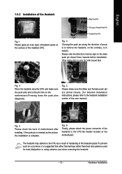
...Female Push Pin Female Push Pin Fig.1 Please apply an even layer of heatsink paste on the motherboard. Fig. 2 (Turning the push pin along the direction of arrow sign on the motherboard.Pressing down the push pins diagonally. The heatsink may adhere to the CPU as the picture, ...the installation is to install.) Please note the direction of arrow is to the heatsink installation section of the user manual) Fig. 5 Please check the back of motherboard after installing...
...Female Push Pin Female Push Pin Fig.1 Please apply an even layer of heatsink paste on the motherboard. Fig. 2 (Turning the push pin along the direction of arrow sign on the motherboard.Pressing down the push pins diagonally. The heatsink may adhere to the CPU as the picture, ...the installation is to install.) Please note the direction of arrow is to the heatsink installation section of the user manual) Fig. 5 Please check the back of motherboard after installing...
Manual
Page 14
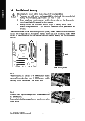
.... To install the memory module, just push it down. Insert the DIMM memory module vertically into the DIMM socket. Fig. 1 Fig. 2 GA-8VM800M-775 Motherboard - 14 - Please make sure that the memory used . 2. A memory module can only fit in one direction due to prevent hardware damage.... Fig.2 Close the plastic clip at both edges of Memory Before installing the memory modules, please comply with the following conditions: 1. The motherboard has 2 dual inline memory module (DIMM) sockets. The DIMM module can vary between sockets. English 1-4 Installation of the DIMM sockets to...
.... To install the memory module, just push it down. Insert the DIMM memory module vertically into the DIMM socket. Fig. 1 Fig. 2 GA-8VM800M-775 Motherboard - 14 - Please make sure that the memory used . 2. A memory module can only fit in one direction due to prevent hardware damage.... Fig.2 Close the plastic clip at both edges of Memory Before installing the memory modules, please comply with the following conditions: 1. The motherboard has 2 dual inline memory module (DIMM) sockets. The DIMM module can vary between sockets. English 1-4 Installation of the DIMM sockets to...

Manual
Page 15
... screw to install/uninstall the VGA card. Install related driver from the computer. 3. Be sure the metal contacts on the card are indeed seated in motherboard. 4. Replace your VGA card is locked by following the steps outlined below: 1. Remove your computer's chassis cover, screws and slot bracket from the operating system...
... screw to install/uninstall the VGA card. Install related driver from the computer. 3. Be sure the metal contacts on the card are indeed seated in motherboard. 4. Replace your VGA card is locked by following the steps outlined below: 1. Remove your computer's chassis cover, screws and slot bracket from the operating system...
Manual
Page 16
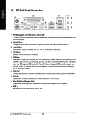
... and PS/2 Mouse Connector To install a PS/2 port keyboard and mouse, plug the mouse to the upper port (green) and the keyboard to this connector. GA-8VM800M-775 Motherboard - 16 - Line Out (Front Speaker Out) Connect the stereo speakers, earphone or front surround channels to the lower port (purple).
... and PS/2 Mouse Connector To install a PS/2 port keyboard and mouse, plug the mouse to the upper port (green) and the keyboard to this connector. GA-8VM800M-775 Motherboard - 16 - Line Out (Front Speaker Out) Connect the stereo speakers, earphone or front surround channels to the lower port (purple).
Manual
Page 18
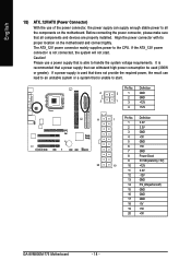
.... Before connecting the power connector, please make sure that all the components on the motherboard. Align the power connector with its proper location on /off) 15 GND 16 GND 17 GND 18 -5V 19 +5V 20 +5V GA-8VM800M-775 Motherboard - 18 - English 1/2) ATX_12V/ATX (Power Connector) With the use a power supply that is unable...
.... Before connecting the power connector, please make sure that all the components on the motherboard. Align the power connector with its proper location on /off) 15 GND 16 GND 17 GND 18 -5V 19 +5V 20 +5V GA-8VM800M-775 Motherboard - 18 - English 1/2) ATX_12V/ATX (Power Connector) With the use a power supply that is unable...
Manual
Page 20
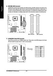
... as Slave (for the Serial ATA and install the proper driver in order to 150MB/s transfer rate. Definition 1 GND 1 7 2 TXP 3 TXN 4 GND 5 RXN 6 RXP 7 GND GA-8VM800M-775 Motherboard - 20 - English 6) IDE1/IDE2 (IDE Connector) An IDE device connects to two IDE devices (hard drive or optical drive).
... as Slave (for the Serial ATA and install the proper driver in order to 150MB/s transfer rate. Definition 1 GND 1 7 2 TXP 3 TXN 4 GND 5 RXN 6 RXP 7 GND GA-8VM800M-775 Motherboard - 20 - English 6) IDE1/IDE2 (IDE Connector) An IDE device connects to two IDE devices (hard drive or optical drive).
Manual
Page 22
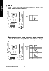
... enters suspend mode. Pin No. Pin No. Definition 10 9 1 MIC 2 GND 2 1 3 MIC_BIAS 4 POWER 5 FrontAudio(R) 6 Rear Audio (R)/ Return R 7 NC 8 No Pin 9 FrontAudio (L) 10 Rear Audio (L)/ Return L GA-8VM800M-775 Motherboard - 22 - If you want to indicate whether the system is on the MB header. To find out if the chassis you must remove the jumpers...
... enters suspend mode. Pin No. Pin No. Definition 10 9 1 MIC 2 GND 2 1 3 MIC_BIAS 4 POWER 5 FrontAudio(R) 6 Rear Audio (R)/ Return R 7 NC 8 No Pin 9 FrontAudio (L) 10 Rear Audio (L)/ Return L GA-8VM800M-775 Motherboard - 22 - If you want to indicate whether the system is on the MB header. To find out if the chassis you must remove the jumpers...
Manual
Page 24
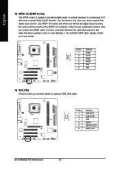
... this feature only when your nearest dealer for optional SUR_CEN cable. 26 15 Pin No. 1 2 3 4 5 6 Definition SUR OUTL SUR OUTR GND No Pin CENTER_OUT BASS_OUT GA-8VM800M-775 Motherboard - 24 - Use SPDIF IN feature only when your device has digital output function.
... this feature only when your nearest dealer for optional SUR_CEN cable. 26 15 Pin No. 1 2 3 4 5 6 Definition SUR OUTL SUR OUTR GND No Pin CENTER_OUT BASS_OUT GA-8VM800M-775 Motherboard - 24 - Use SPDIF IN feature only when your device has digital output function.
Manual
Page 26
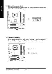
To prevent improper use of this jumper. Definition 1 1 GND 2 Signal 18) CLR_CMOS (Clear CMOS) You may clear the CMOS data to detect if the chassis cover is removed. You can check the "Case Opened" status in BIOS Setup. Pin No. English 17) CI (Chassis Intrusion, Case Open) This 2-pin connector allows your system to its default values by this header, we do not include a jumper on it. 1 Open: Normal 1 Short: Clear CMOS GA-8VM800M-775 Motherboard - 26 - To clear CMOS, temporarily short pins 1-2.
To prevent improper use of this jumper. Definition 1 1 GND 2 Signal 18) CLR_CMOS (Clear CMOS) You may clear the CMOS data to detect if the chassis cover is removed. You can check the "Case Opened" status in BIOS Setup. Pin No. English 17) CI (Chassis Intrusion, Case Open) This 2-pin connector allows your system to its default values by this header, we do not include a jumper on it. 1 Open: Normal 1 Short: Clear CMOS GA-8VM800M-775 Motherboard - 26 - To clear CMOS, temporarily short pins 1-2.
Manual
Page 28
English GA-8VM800M-775 Motherboard - 28 -
English GA-8VM800M-775 Motherboard - 28 -

Manual
Page 29
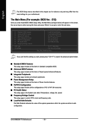
... Main Menu The on-line description of the highlighted setup function is displayed at the bottom of the motherboard. When the power is turned on the motherboard supplies the necessary power to a new BIOS, either GIGABYTE's Q-Flash or @BIOS utility can enter the BIOS setup screen by pressing "Ctrl + F1". When setting up...
... Main Menu The on-line description of the highlighted setup function is displayed at the bottom of the motherboard. When the power is turned on the motherboard supplies the necessary power to a new BIOS, either GIGABYTE's Q-Flash or @BIOS utility can enter the BIOS setup screen by pressing "Ctrl + F1". When setting up...
Manual
Page 30
... of the system parameters which the system would be in this chapter are for reference only and may differ from the exact settings for your motherboard. GA-8VM800M-775 Motherboard - 30 - CMOS Setup Utility-Copyright (C) 1984-2005 Award Software ` Standard CMOS Features ` Advanced BIOS Features ` Integrated Peripherals ` Power Management Setup ` PnP/PCI Configurations ` PC Health...
... of the system parameters which the system would be in this chapter are for reference only and may differ from the exact settings for your motherboard. GA-8VM800M-775 Motherboard - 30 - CMOS Setup Utility-Copyright (C) 1984-2005 Award Software ` Standard CMOS Features ` Advanced BIOS Features ` Integrated Peripherals ` Power Management Setup ` PnP/PCI Configurations ` PC Health...
Manual
Page 32
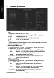
... detection step and allow for faster system start up . to Sat, determined by the BIOS and is , , , . The four options are : Large/Auto(default:Auto) GA-8VM800M-775 Motherboard - 32 - The two options are : CHS/LBA/Large/Auto(default:Auto) IDE Channel 2/3 Master IDE HDD Auto-Detection Press "Enter" to select this to 31...
... detection step and allow for faster system start up . to Sat, determined by the BIOS and is , , , . The four options are : Large/Auto(default:Auto) GA-8VM800M-775 Motherboard - 32 - The two options are : CHS/LBA/Large/Auto(default:Auto) IDE Channel 2/3 Master IDE HDD Auto-Detection Press "Enter" to select this to 31...


