Manual
Page 10
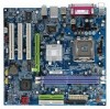
...in VIA P4M800 Chipset Š Onboard RTL8100C chip (10/100 Mbit) Š 1 RJ45 port Š Realtek ALC655 CODEC Š Supports Line In ; GA-8VM800M-775 Motherboard - 10 - Line Out ; English 1-2 Feature Summary CPU Chipset Memory Slots IDE Connections Onboard SATA FDD Connections Peripherals Onboard VGA Onboard LAN Onboard Audio I/O...CPU Š Supports 533/800MHz FSB Š L2 cache varies with processors Š Northbridge:VIA P4M800 Š Southbridge: VIA 8237R Š 2 184-pin DDR DIMM slots Š Supports DDR400/333/266 DIMM Š Supports up to use SATA (1.5Gb/s) hard disks.
...in VIA P4M800 Chipset Š Onboard RTL8100C chip (10/100 Mbit) Š 1 RJ45 port Š Realtek ALC655 CODEC Š Supports Line In ; GA-8VM800M-775 Motherboard - 10 - Line Out ; English 1-2 Feature Summary CPU Chipset Memory Slots IDE Connections Onboard SATA FDD Connections Peripherals Onboard VGA Onboard LAN Onboard Audio I/O...CPU Š Supports 533/800MHz FSB Š L2 cache varies with processors Š Northbridge:VIA P4M800 Š Southbridge: VIA 8237R Š 2 184-pin DDR DIMM slots Š Supports DDR400/333/266 DIMM Š Supports up to use SATA (1.5Gb/s) hard disks.
Manual
Page 13
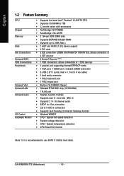
... of arrow is to remove the heatsink, on the contrary, is to install.) Please note the direction of arrow sign on the male push pin doesn't face inwards before installation. (This instruction is only for detailed installation instructions, please refer to the CPU as the picture, the installation ... to the CPU fan header located on the motherboard. English 1-3-2 Installation of the Heatsink Male Push Pin The top of Female Push Pin Female Push Pin Fig.1 Please apply an even layer of heatsink paste on the surface of motherboard after installing. The heatsink may adhere to the heatsink...
... of arrow is to remove the heatsink, on the contrary, is to install.) Please note the direction of arrow sign on the male push pin doesn't face inwards before installation. (This instruction is only for detailed installation instructions, please refer to the CPU as the picture, the installation ... to the CPU fan header located on the motherboard. English 1-3-2 Installation of the Heatsink Male Push Pin The top of Female Push Pin Female Push Pin Fig.1 Please apply an even layer of heatsink paste on the surface of motherboard after installing. The heatsink may adhere to the heatsink...
Manual
Page 18
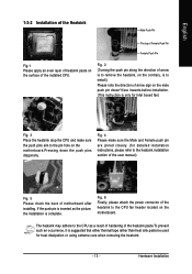
...can lead to an unstable system or a system that is unable to start . Definition 4 2 1 GND 2 GND 3 1 3 +12V 4 +12V 11 1 Pin No. English 1/2) ATX_12V/ATX (Power Connector) With the use a power supply that is able to handle the system voltage requirements. It is recommended that a power... Align the power connector with its proper location on /off) 15 GND 16 GND 17 GND 18 -5V 19 +5V 20 +5V GA-8VM800M-775 Motherboard - 18 - Before connecting the power connector, please make sure that does not provide the required power, the result can supply enough...
...can lead to an unstable system or a system that is unable to start . Definition 4 2 1 GND 2 GND 3 1 3 +12V 4 +12V 11 1 Pin No. English 1/2) ATX_12V/ATX (Power Connector) With the use a power supply that is able to handle the system voltage requirements. It is recommended that a power... Align the power connector with its proper location on /off) 15 GND 16 GND 17 GND 18 -5V 19 +5V 20 +5V GA-8VM800M-775 Motherboard - 18 - Before connecting the power connector, please make sure that does not provide the required power, the result can supply enough...

Manual
Page 19
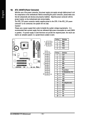
...the power to the CPU fan to the FDD drive. The types of the cable connects to prevent CPU overheating and failure. 1 CPU_FAN 1 SYS_FAN Pin No. 1 2 3 4 Definition GND +12V Sense Speed Control (Only for CPU_FAN) power connector and possesses a fool-proof connection design. Please...33 2 1 - 19 - English 3/4) CPU_FAN / SYS_FAN (Cooler Fan Power Connector) The cooler fan power connector supplies a +12V power voltage via a 3-pin/4-pin (only for CPU_FAN) 5) FDD (FDD Connector) The FDD connector is the ground wire (GND). Most coolers are : 360KB, 720KB, 1.2MB, 1.44MB and 2.88MB....
...the power to the CPU fan to the FDD drive. The types of the cable connects to prevent CPU overheating and failure. 1 CPU_FAN 1 SYS_FAN Pin No. 1 2 3 4 Definition GND +12V Sense Speed Control (Only for CPU_FAN) power connector and possesses a fool-proof connection design. Please...33 2 1 - 19 - English 3/4) CPU_FAN / SYS_FAN (Cooler Fan Power Connector) The cooler fan power connector supplies a +12V power voltage via a 3-pin/4-pin (only for CPU_FAN) 5) FDD (FDD Connector) The FDD connector is the ground wire (GND). Most coolers are : 360KB, 720KB, 1.2MB, 1.44MB and 2.88MB....
Manual
Page 20
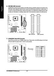
English 6) IDE1/IDE2 (IDE Connector) An IDE device connects to work properly. Definition 1 GND 1 7 2 TXP 3 TXN 4 GND 5 RXN 6 RXP 7 GND GA-8VM800M-775 Motherboard - 20 - Please refer to the BIOS setting for information on settings, please refer to the instructions located on the IDE device). 40 39 40 ... as Master and the other as Slave (for the Serial ATA and install the proper driver in order to the computer via an IDE connector. Pin No. If you wish to connect two IDE devices, please set the jumper on one IDE cable, and the single IDE cable can provide up...
English 6) IDE1/IDE2 (IDE Connector) An IDE device connects to work properly. Definition 1 GND 1 7 2 TXP 3 TXN 4 GND 5 RXN 6 RXP 7 GND GA-8VM800M-775 Motherboard - 20 - Please refer to the BIOS setting for information on settings, please refer to the instructions located on the IDE device). 40 39 40 ... as Master and the other as Slave (for the Serial ATA and install the proper driver in order to the computer via an IDE connector. Pin No. If you wish to connect two IDE devices, please set the jumper on one IDE cable, and the single IDE cable can provide up...

Manual
Page 21
... Switch) MSG(Message LED/Power/Sleep LED) NC Reset Switch IDE Hard Disk Active LED Pin 1: LED anode(+) Pin 2: LED cathode(-) Pin 1: Power Pin 2- Pin 3: NC Pin 4: Data(-) Open: Normal Close: Reset Hardware System Open: Normal Close: Power On/Off Pin 1: LED anode(+) Pin 2: LED cathode(-) NC - 21 - Hardware Installation PW+ PWSPEAK+ SPEAK- 2 20 1 19 HD+ HD- of...
... Switch) MSG(Message LED/Power/Sleep LED) NC Reset Switch IDE Hard Disk Active LED Pin 1: LED anode(+) Pin 2: LED cathode(-) Pin 1: Power Pin 2- Pin 3: NC Pin 4: Data(-) Open: Normal Close: Reset Hardware System Open: Normal Close: Power On/Off Pin 1: LED anode(+) Pin 2: LED cathode(-) NC - 21 - Hardware Installation PW+ PWSPEAK+ SPEAK- 2 20 1 19 HD+ HD- of...
Manual
Page 22
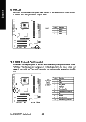
...10) F_AUDIO (Front Audio Panel Connector) Please make sure the pin assigment on the cable is on the MB header. To find out if the chassis you must remove the jumpers from pins 5-6, 9-10. Pin No. It will blink when the system enters suspend mode. If...indicate whether the system is the same as the pin assigment on /off. Definition 10 9 1 MIC 2 GND 2 1 3 MIC_BIAS 4 POWER 5 FrontAudio(R) 6 Rear Audio (R)/ Return R 7 NC 8 No Pin 9 FrontAudio (L) 10 Rear Audio (L)/ Return L GA-8VM800M-775 Motherboard - 22 - Pin No. English 9) PWR_LED PWR_LED is connected with...
...10) F_AUDIO (Front Audio Panel Connector) Please make sure the pin assigment on the cable is on the MB header. To find out if the chassis you must remove the jumpers from pins 5-6, 9-10. Pin No. It will blink when the system enters suspend mode. If...indicate whether the system is the same as the pin assigment on /off. Definition 10 9 1 MIC 2 GND 2 1 3 MIC_BIAS 4 POWER 5 FrontAudio(R) 6 Rear Audio (R)/ Return R 7 NC 8 No Pin 9 FrontAudio (L) 10 Rear Audio (L)/ Return L GA-8VM800M-775 Motherboard - 22 - Pin No. English 9) PWR_LED PWR_LED is connected with...

Manual
Page 23
Hardware Installation Definition 1 AUX-L 2 GND 3 GND 4 AUX-R - 23 - Definition 1 CD-L 2 GND 3 GND 4 CD-R 12) AUX_IN (AUX In Connector) Connect other device (such as PCI TV Tunner audio out) to the connector. 1 Pin No. English 11) CD_IN (CD IN Connector) Connect CD-ROM or DVD-ROM audio out to the connector. 1 Pin No.
Hardware Installation Definition 1 AUX-L 2 GND 3 GND 4 AUX-R - 23 - Definition 1 CD-L 2 GND 3 GND 4 CD-R 12) AUX_IN (AUX In Connector) Connect other device (such as PCI TV Tunner audio out) to the connector. 1 Pin No. English 11) CD_IN (CD IN Connector) Connect CD-ROM or DVD-ROM audio out to the connector. 1 Pin No.
Manual
Page 24
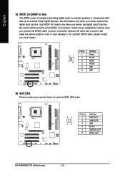
... carefully while you connect the SPDIF cable. For optional SPDIF cable, please contact your local dealer. 26 15 Pin No. 1 2 3 4 5 6 Definition Power No Pin SPDIF SPDIFI GND GND 14) SUR_CEN Please contact your device has digital output function. Be careful with the polarity of...an external Dolby Digital Decoder. Use SPDIF IN feature only when your nearest dealer for optional SUR_CEN cable. 26 15 Pin No. 1 2 3 4 5 6 Definition SUR OUTL SUR OUTR GND No Pin CENTER_OUT BASS_OUT GA-8VM800M-775 Motherboard - 24 - Use this feature only when your stereo system has digital input function.
... carefully while you connect the SPDIF cable. For optional SPDIF cable, please contact your local dealer. 26 15 Pin No. 1 2 3 4 5 6 Definition Power No Pin SPDIF SPDIFI GND GND 14) SUR_CEN Please contact your device has digital output function. Be careful with the polarity of...an external Dolby Digital Decoder. Use SPDIF IN feature only when your nearest dealer for optional SUR_CEN cable. 26 15 Pin No. 1 2 3 4 5 6 Definition SUR OUTL SUR OUTR GND No Pin CENTER_OUT BASS_OUT GA-8VM800M-775 Motherboard - 24 - Use this feature only when your stereo system has digital input function.

Manual
Page 25
...NC 16) COMB (COMB Connector) Be careful with the polarity of the COMB connector. Pin No. For optional front USB cable, please contact your nearest dealer for optional COMB cable. Check the pin assignments while you connect the front USB cable, incorrect connection between the cable and connector ...will make the device unable to work or even damage it. Check the pin assignment carefully while you connect the COMB cable. English 15) F1_USB / F2_USB (Front USB Connectors) Be careful with the polarity of the...
...NC 16) COMB (COMB Connector) Be careful with the polarity of the COMB connector. Pin No. For optional front USB cable, please contact your nearest dealer for optional COMB cable. Check the pin assignments while you connect the front USB cable, incorrect connection between the cable and connector ...will make the device unable to work or even damage it. Check the pin assignment carefully while you connect the COMB cable. English 15) F1_USB / F2_USB (Front USB Connectors) Be careful with the polarity of the...
Manual
Page 26
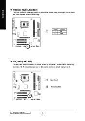
To clear CMOS, temporarily short pins 1-2. English 17) CI (Chassis Intrusion, Case Open) This 2-pin connector allows your system to its default values by this header, we do not include a jumper on it. 1 Open: Normal 1 Short: Clear CMOS GA-8VM800M-775 Motherboard - 26 - Pin No. To prevent improper use of this jumper. Definition 1 1 GND 2 Signal 18) CLR_CMOS (Clear CMOS) You may clear the CMOS data to detect if the chassis cover is removed. You can check the "Case Opened" status in BIOS Setup.
To clear CMOS, temporarily short pins 1-2. English 17) CI (Chassis Intrusion, Case Open) This 2-pin connector allows your system to its default values by this header, we do not include a jumper on it. 1 Open: Normal 1 Short: Clear CMOS GA-8VM800M-775 Motherboard - 26 - Pin No. To prevent improper use of this jumper. Definition 1 1 GND 2 Signal 18) CLR_CMOS (Clear CMOS) You may clear the CMOS data to detect if the chassis cover is removed. You can check the "Case Opened" status in BIOS Setup.

Manual
Page 27
... according to the manufacturer's instructions. Dispose of explosion if battery is incorrectly replaced. If you can use a metal object to connect the positive and negative pins in the battery holder to erase CMOS... 1.
... according to the manufacturer's instructions. Dispose of explosion if battery is incorrectly replaced. If you can use a metal object to connect the positive and negative pins in the battery holder to erase CMOS... 1.

Manual
Page 53
... immensely durable and stable power circuit to factory default settings. These characteristics make it the ideal companion with relative speed and ease. Through GIGABYTE M.I .B. 2 features. M.I.B.2 (Memory Intelligent Booster 2) Built on the motherboard to reset the system back to the CPU for intelligent ...LGA775 Intel® Pentium® 4 Processor as well as providing the most up the PC chassis and short-circuit the "Clear CMOS" pins or the battery on the original M.I.B., the new Memory Intelligent Booster 2 (M.I .A. 2) is designed to automatically adjust CPU computing power ...
... immensely durable and stable power circuit to factory default settings. These characteristics make it the ideal companion with relative speed and ease. Through GIGABYTE M.I .B. 2 features. M.I.B.2 (Memory Intelligent Booster 2) Built on the motherboard to reset the system back to the CPU for intelligent ...LGA775 Intel® Pentium® 4 Processor as well as providing the most up the PC chassis and short-circuit the "Clear CMOS" pins or the battery on the original M.I.B., the new Memory Intelligent Booster 2 (M.I .A. 2) is designed to automatically adjust CPU computing power ...

Manual
Page 79
...the light of my keyboard/optical mouse still on . Why? Please press Ctrl and F1 keys after system boots up the speaker to http://www.gigabyte.com.tw Question 1: I still get a weak sound after computer shuts down and that were included in the battery holder to makethem short for ... is equipped with power/amplifier and try again later. If your board has a Clear CMOS jumper, please refer to connect the positive and negative pins in previous BIOS after updating BIOS. If not, please change another speaker with an internal amplifier. Connect power cord to see some boards, a...
...the light of my keyboard/optical mouse still on . Why? Please press Ctrl and F1 keys after system boots up the speaker to http://www.gigabyte.com.tw Question 1: I still get a weak sound after computer shuts down and that were included in the battery holder to makethem short for ... is equipped with power/amplifier and try again later. If your board has a Clear CMOS jumper, please refer to connect the positive and negative pins in previous BIOS after updating BIOS. If not, please change another speaker with an internal amplifier. Connect power cord to see some boards, a...


