User Manual
Page 1
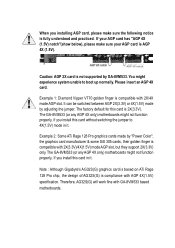
...but they support 2X(3.3V) only. Note : Although Gigabyte's AG32S(G) graphics card is based on ATi Rage 128 Pro chip, the design of AG32S(G) is compatible with AGP 4X(1.5V) specification. The GA-8VM533 (or any AGP 4X only) motherboards might not function properly, if you installing AGP card,...adjusting the jumper. The factory default for this card is compatible with GA-8VM533 based motherboards. It can be switched between AGP 2X(3.3V) or 4X(1.5V) mode by GA-8VM533. The GA-8VM533 (or any AGP 4X only) motherboards might experience system unable to 4X(1.5V) mode in it . Example...
...but they support 2X(3.3V) only. Note : Although Gigabyte's AG32S(G) graphics card is based on ATi Rage 128 Pro chip, the design of AG32S(G) is compatible with AGP 4X(1.5V) specification. The GA-8VM533 (or any AGP 4X only) motherboards might not function properly, if you installing AGP card,...adjusting the jumper. The factory default for this card is compatible with GA-8VM533 based motherboards. It can be switched between AGP 2X(3.3V) or 4X(1.5V) mode by GA-8VM533. The GA-8VM533 (or any AGP 4X only) motherboards might experience system unable to 4X(1.5V) mode in it . Example...

User Manual
Page 2
Due to update the information contained herein. The author assumes no responsibility for any labels on motherboard, this may appear in technology, some of the specifications might be out of date before publication of their respective owners. Third-party brands and names are the property of this document nor does the author make a commitment to rapid change in this booklet. Please do not remove any errors or omissions that may void the warranty of this motherboard.
Due to update the information contained herein. The author assumes no responsibility for any labels on motherboard, this may appear in technology, some of the specifications might be out of date before publication of their respective owners. Third-party brands and names are the property of this document nor does the author make a commitment to rapid change in this booklet. Please do not remove any errors or omissions that may void the warranty of this motherboard.
User Manual
Page 4
...: 17358 Railroad Street City of Industry, CA 91748 Phone/Fax No: (818) 854-9338/ (818) 854-9339 hereby declares that the product Product Name: Motherboard Model Number: GA-8VM533 Conforms to the following specifications: FCC Part 15, Subpart B, Section 15.107(a) and Section 15.109(a), Class B Digital Device Supplementary Information: This device...
...: 17358 Railroad Street City of Industry, CA 91748 Phone/Fax No: (818) 854-9338/ (818) 854-9339 hereby declares that the product Product Name: Motherboard Model Number: GA-8VM533 Conforms to the following specifications: FCC Part 15, Subpart B, Section 15.107(a) and Section 15.109(a), Class B Digital Device Supplementary Information: This device...
User Manual
Page 5
GA-8VM533 P4 Titan Series Motherboard USER'S MANUAL Pentium® 4ProcessorMotherboard Rev. 1002 12ME-8VM533-1002
GA-8VM533 P4 Titan Series Motherboard USER'S MANUAL Pentium® 4ProcessorMotherboard Rev. 1002 12ME-8VM533-1002
User Manual
Page 6
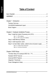
English Table of Content Item Checklist 4 WARNING 4 Chapter 1 Introduction 5 Features Summary 5 GA-8VM533 Motherboard Layout 7 Block Diagram 8 Chapter 2 Hardware Installation Process 11 Step 1: Install the Central Processing Unit (CPU 12 Step 1-1: CPU Installation 12 Step 1-2: CPU Cooling Fan Installation ... 27 The Main Menu (For example: BIOS Ver. : F1 28 Standard CMOS Features 30 Advanced BIOS Features 33 Integrated Peripherals 35 Power Management Setup 38 GA-8VM533 Motherboard - 2 -
English Table of Content Item Checklist 4 WARNING 4 Chapter 1 Introduction 5 Features Summary 5 GA-8VM533 Motherboard Layout 7 Block Diagram 8 Chapter 2 Hardware Installation Process 11 Step 1: Install the Central Processing Unit (CPU 12 Step 1-1: CPU Installation 12 Step 1-2: CPU Cooling Fan Installation ... 27 The Main Menu (For example: BIOS Ver. : F1 28 Standard CMOS Features 30 Advanced BIOS Features 33 Integrated Peripherals 35 Power Management Setup 38 GA-8VM533 Motherboard - 2 -
User Manual
Page 8
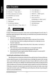
... base without worrying aboutshort circuits. In this way you should follow some precautions wheneveryou work on your computer. 1. GA-8VM533 Motherboard - 4 - Use a grounded wrist strap before handling computercomponents.Ifyou do not become alarmed you plug in or ...hole, otherwise itmay damage the boardorcause boardmalfunctioning. Installing the motherboard to a metalobject, such as the power supplycase. 3. English Item Checklist The GA-8VM533 motherboard IDE cable x 1 / Floppy cable x 1 CD for motherboard driver & utility GA-8VM533 user's manual I/O Shield Quick PC Installation Guide...
... base without worrying aboutshort circuits. In this way you should follow some precautions wheneveryou work on your computer. 1. GA-8VM533 Motherboard - 4 - Use a grounded wrist strap before handling computercomponents.Ifyou do not become alarmed you plug in or ...hole, otherwise itmay damage the boardorcause boardmalfunctioning. Installing the motherboard to a metalobject, such as the power supplycase. 3. English Item Checklist The GA-8VM533 motherboard IDE cable x 1 / Floppy cable x 1 CD for motherboard driver & utility GA-8VM533 user's manual I/O Shield Quick PC Installation Guide...
User Manual
Page 10
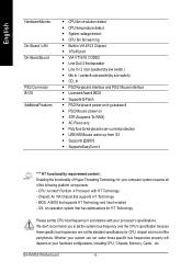
... over the CPU's specification because these specific bus frequencies properly will depend on - Chipset: An VIA Chipset that supports HT Technology and has it enabled - GA-8VM533 Motherboard - 6 - English Hardware Monitor On-Board LAN On-Board Sound PS/2 Connector BIOS Additional Features - System voltage detect - CPU fan fail warning - STR(Suspend-To...
... over the CPU's specification because these specific bus frequencies properly will depend on - Chipset: An VIA Chipset that supports HT Technology and has it enabled - GA-8VM533 Motherboard - 6 - English Hardware Monitor On-Board LAN On-Board Sound PS/2 Connector BIOS Additional Features - System voltage detect - CPU fan fail warning - STR(Suspend-To...

User Manual
Page 14
English GA-8VM533 Motherboard - 10 -
English GA-8VM533 Motherboard - 10 -
User Manual
Page 16
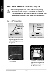
... "cough"made. 2.Pull the rodto the 90-degree directly. Pin1 indicator Pin1 indicator 3. Please make sure the CPU type is supported by the motherboard. 2. CPU Top View GA-8VM533 Motherboard 4. Angling the rod to65-degree maybe feelakind oftight,and then continue pulltherod to 650 Socket Actuation Lever 1. Locate Pin 1 in the socket and...
... "cough"made. 2.Pull the rodto the 90-degree directly. Pin1 indicator Pin1 indicator 3. Please make sure the CPU type is supported by the motherboard. 2. CPU Top View GA-8VM533 Motherboard 4. Angling the rod to65-degree maybe feelakind oftight,and then continue pulltherod to 650 Socket Actuation Lever 1. Locate Pin 1 in the socket and...

User Manual
Page 17
..., or remove the cooling fan with the cooling fan, and might damage the processor. Fasten the cooling fan supportingbase onto the CPU socket on the motherboard. 2. During this completes the installation. Please refer to the hardening of the thermal paste. Make sure the CPU fan power cable is plugged to the...
..., or remove the cooling fan with the cooling fan, and might damage the processor. Fasten the cooling fan supportingbase onto the CPU socket on the motherboard. 2. During this completes the installation. Please refer to the hardening of the thermal paste. Make sure the CPU fan power cable is plugged to the...
User Manual
Page 18
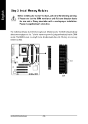
... 2 dual inline memory module (DIMM) sockets. The BIOS will cause improper installation. Me mory size ca n va ry between sockets. Notch DDR GA-8VM533 Motherboard - 14 - Th e DIMM module ca n on e direction due to the following warning: 1. Please note that the DIMM module can only fit in on ly fit ...
... 2 dual inline memory module (DIMM) sockets. The BIOS will cause improper installation. Me mory size ca n va ry between sockets. Notch DDR GA-8VM533 Motherboard - 14 - Th e DIMM module ca n on e direction due to the following warning: 1. Please note that the DIMM module can only fit in on ly fit ...

User Manual
Page 20
...- English Step 3: Install expansion cards 1. Install related driver from BIOS. 8. Read the related expansion card's instruction document before install the expansion card into expansion slotin motherboard. 4. Power on the computer, ifnecessary, setup BIOS utility of the AGP slot when you try to secure the slotbracketofthe expansion card...
...- English Step 3: Install expansion cards 1. Install related driver from BIOS. 8. Read the related expansion card's instruction document before install the expansion card into expansion slotin motherboard. 4. Power on the computer, ifnecessary, setup BIOS utility of the AGP slot when you try to secure the slotbracketofthe expansion card...
User Manual
Page 22
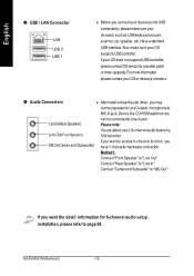
..." to "Line Out" Connect"Rear Speaker" to "Line In" Connect "Centerand Subwoofer" to Line-In jack. Have a standard USB interface. can be connected to "MICOut". GA-8VM533 Motherboard - 18 - Device like CD-ROM,walkman etc. Please note: You are ableto use2-/6-channelaudio feature by S/W selection. English w USB / LAN Connector LAN USB 0 USB...
..." to "Line Out" Connect"Rear Speaker" to "Line In" Connect "Centerand Subwoofer" to Line-In jack. Have a standard USB interface. can be connected to "MICOut". GA-8VM533 Motherboard - 18 - Device like CD-ROM,walkman etc. Please note: You are ableto use2-/6-channelaudio feature by S/W selection. English w USB / LAN Connector LAN USB 0 USB...

User Manual
Page 24
... +12V 11 3.3V 12 -12V 13 GND 20 10 14 PS_ON(softon/off) 15 GND 16 GND 17 GND 18 -5V 19 VCC 20 VCC GA-8VM533 Motherboard - 20 -
... +12V 11 3.3V 12 -12V 13 GND 20 10 14 PS_ON(softon/off) 15 GND 16 GND 17 GND 18 -5V 19 VCC 20 VCC GA-8VM533 Motherboard - 20 -

User Manual
Page 26
... erase CMOS... 1. If you want to IDE2. Rem ove the battery, wait for 30 second. 3. Replace only with the Pin1. 40 39 6) BAT (BATTERY) GA-8VM533 Motherboard 2 1 IDE2 IDE1 + CAUT ION Danger of explosion if battery is incorrectly rep lace d. Dispose of the ribbon cable must be the sam e side with the...
... erase CMOS... 1. If you want to IDE2. Rem ove the battery, wait for 30 second. 3. Replace only with the Pin1. 40 39 6) BAT (BATTERY) GA-8VM533 Motherboard 2 1 IDE2 IDE1 + CAUT ION Danger of explosion if battery is incorrectly rep lace d. Dispose of the ribbon cable must be the sam e side with the...
User Manual
Page 28
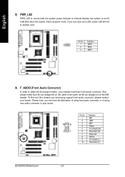
... using rear audio connector to play sound. 10 9 21 Pin No. 1 2 3 4 5 6 7 8 9 10 Definition MIC GND REF Power FrontAudio (R) RearAudio (R) Reserved No Pin FrontAudio (L) RearAudio (L) GA-8VM533 Motherboard - 24 - Please note, you can have front audio connector. Definition 1 1 MPD+ 2 MPD- 3 MPD- 9) F_AUDIO (Front Audio Connector) In order to another color. To find out...
... using rear audio connector to play sound. 10 9 21 Pin No. 1 2 3 4 5 6 7 8 9 10 Definition MIC GND REF Power FrontAudio (R) RearAudio (R) Reserved No Pin FrontAudio (L) RearAudio (L) GA-8VM533 Motherboard - 24 - Please note, you can have front audio connector. Definition 1 1 MPD+ 2 MPD- 3 MPD- 9) F_AUDIO (Front Audio Connector) In order to another color. To find out...

User Manual
Page 30
English GA-8VM533 Motherboard - 26 -
English GA-8VM533 Motherboard - 26 -
User Manual
Page 32
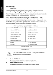
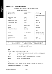
... 1: MainMenu If you can't find the set ting you want, p lease press "Ctrl+F1" to select from eight setup functions and two exit choices. GA-8VM533 Motherboard - 28 - English GETTING HELP Mai n Menu The on the screen. To exit the Help Window press . The Main Menu allows you enterAward BIOS CMOS Setup...
... 1: MainMenu If you can't find the set ting you want, p lease press "Ctrl+F1" to select from eight setup functions and two exit choices. GA-8VM533 Motherboard - 28 - English GETTING HELP Mai n Menu The on the screen. To exit the Help Window press . The Main Menu allows you enterAward BIOS CMOS Setup...
User Manual
Page 34
..., determined by the BIOS and is , , , . The time is 13:00:00. For example, 1 p.m. is calculated base on the 24-hour military-time clock. GA-8VM533 Motherboard - 30 - to Dec. 1 to 2098 higf: Mov e Enter:Select +/-/PU/PD:Value F10:Sav e ESC:Ex it F1:General Help F5:Prev ious Values F6...
..., determined by the BIOS and is , , , . The time is 13:00:00. For example, 1 p.m. is calculated base on the 24-hour military-time clock. GA-8VM533 Motherboard - 30 - to Dec. 1 to 2098 higf: Mov e Enter:Select +/-/PU/PD:Value F10:Sav e ESC:Ex it F1:General Help F5:Prev ious Values F6...
User Manual
Page 36
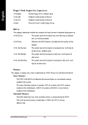
... amount of Drive B. Base Memory The POST of the BIOS will be prompted. it will stop for a keyboard error; GA-8VM533 Motherboard - 32 - Halt on the motherboard. it will stop for any error that may be detected and you will not stop for all other errors. The value ...for a disk error; Extended Memory The BIOS determines how much extended memory is typically 512 K for systems with 512 K memory installed on the motherboard, or 640 K for systems with 640 K or more memory installed on The category determines whether the computer will not stop for a keyboard ...
... amount of Drive B. Base Memory The POST of the BIOS will be prompted. it will stop for a keyboard error; GA-8VM533 Motherboard - 32 - Halt on the motherboard. it will stop for any error that may be detected and you will not stop for all other errors. The value ...for a disk error; Extended Memory The BIOS determines how much extended memory is typically 512 K for systems with 512 K memory installed on the motherboard, or 640 K for systems with 640 K or more memory installed on The category determines whether the computer will not stop for a keyboard ...


