Manual
Page 1
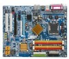
GA-8N-SLI Royal/ GA-8N-SLI Pro/ GA-8N-SLI Intel® Pentium® Processor Extreme Edition Intel® Pentium® D / Pentium® 4 LGA775 Processor Motherboard User's Manual Rev. 1004 12ME-8NSLIRO-1004
GA-8N-SLI Royal/ GA-8N-SLI Pro/ GA-8N-SLI Intel® Pentium® Processor Extreme Edition Intel® Pentium® D / Pentium® 4 LGA775 Processor Motherboard User's Manual Rev. 1004 12ME-8NSLIRO-1004
Manual
Page 6
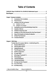
Only for GA-8N-SLI Royal. Table of Contents GA-8N-SLI Royal / GA-8N-SLI Pro / GA-8N-SLI Motherboard Layout 8 Block Diagram ...9 Chapter 1 Hardware Installation 11 1-1 Considerations Prior to Installation 11 1-2 Feature Summary 12 1-3 Installation of ... Configuration 20 1-9 I/O Back Panel Introduction 23 1-10 Connectors Introduction 24 Chapter 2 BIOS Setup 35 The Main Menu (For example: BIOS Ver. : GA-8N-SLI Royal F3l 36 2-1 Standard CMOS Features 38 2-2 Advanced BIOS Features 40 2-3 IntegratedPeripherals 42 2-4 Power Management Setup 45 2-5 PnP/PCI Configurations 47 2-6 PC ...
Only for GA-8N-SLI Royal. Table of Contents GA-8N-SLI Royal / GA-8N-SLI Pro / GA-8N-SLI Motherboard Layout 8 Block Diagram ...9 Chapter 1 Hardware Installation 11 1-1 Considerations Prior to Installation 11 1-2 Feature Summary 12 1-3 Installation of ... Configuration 20 1-9 I/O Back Panel Introduction 23 1-10 Connectors Introduction 24 Chapter 2 BIOS Setup 35 The Main Menu (For example: BIOS Ver. : GA-8N-SLI Royal F3l 36 2-1 Standard CMOS Features 38 2-2 Advanced BIOS Features 40 2-3 IntegratedPeripherals 42 2-4 Power Management Setup 45 2-5 PnP/PCI Configurations 47 2-6 PC ...
Manual
Page 8
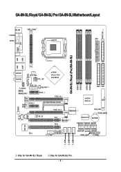
GA-8N-SLI Royal / GA-8N-SLI Pro / GA-8N-SLI Motherboard Layout KB_MS VRM_CONN COAXIAL ATX SPDIF_O LGA775 PWR_FAN COMA LPT GA-8N-SLI Royal (Pro)/GA-8N-SLI DDRII1 DDRII2 DDRII3 DDRII4 LAN1 LAN2 USB FDD USB Marvell Phy (LAN2) AUDIO1 AUDIO2 CPU_FAN ATX_12V nVIDIA® nForce 4 SLI Intel Edition F_AUDIO Marvell 8053 (LAN1) PCIE_12V Main BIOS Backup PCIE_2 BIOS NB_FAN PCIE_1 PCIE_16_1 SLI Switch Module Socket PCIE_16_2...
GA-8N-SLI Royal / GA-8N-SLI Pro / GA-8N-SLI Motherboard Layout KB_MS VRM_CONN COAXIAL ATX SPDIF_O LGA775 PWR_FAN COMA LPT GA-8N-SLI Royal (Pro)/GA-8N-SLI DDRII1 DDRII2 DDRII3 DDRII4 LAN1 LAN2 USB FDD USB Marvell Phy (LAN2) AUDIO1 AUDIO2 CPU_FAN ATX_12V nVIDIA® nForce 4 SLI Intel Edition F_AUDIO Marvell 8053 (LAN1) PCIE_12V Main BIOS Backup PCIE_2 BIOS NB_FAN PCIE_1 PCIE_16_1 SLI Switch Module Socket PCIE_16_2...
Manual
Page 9
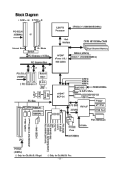
... x 8 PCI-ECLK (100MHz) or LGA775 Processor CPUCLK+/-(1066/800/533MHz) Host Interface DDRII 667/533MHz DIMM Normal Mode SLI Mode Switch PCI Express x 16 Bus PCI Express Bus x1 x1 x1 nVIDIA® nForce 4 SLI Intel Edition Dual Channel Memory NBCLK (25MHz) HCLK+/- (133/200/266MHz) PCI-ECLK (100MHz) Marvell 8053 2 PCI... Channel 3 IEEE1394b Surround Speaker Out Center/Subwoofer Speaker Out Side Speaker Out MIC Line-Out Line-In SPDIF In SPDIF Out PCICLK (33MHz) Only for GA-8N-SLI Pro. - 9 - Only for GA-8N-SLI Royal.
... x 8 PCI-ECLK (100MHz) or LGA775 Processor CPUCLK+/-(1066/800/533MHz) Host Interface DDRII 667/533MHz DIMM Normal Mode SLI Mode Switch PCI Express x 16 Bus PCI Express Bus x1 x1 x1 nVIDIA® nForce 4 SLI Intel Edition Dual Channel Memory NBCLK (25MHz) HCLK+/- (133/200/266MHz) PCI-ECLK (100MHz) Marvell 8053 2 PCI... Channel 3 IEEE1394b Surround Speaker Out Center/Subwoofer Speaker Out Side Speaker Out MIC Line-Out Line-In SPDIF In SPDIF Out PCICLK (33MHz) Only for GA-8N-SLI Pro. - 9 - Only for GA-8N-SLI Royal.
Manual
Page 12
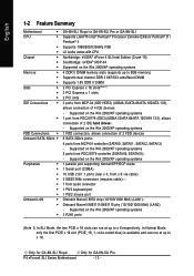
...-04 (IDE1/IDE2) (UDMA 33/ATA 66/ATA 100/ATA 133), allows connection of 2 IDE hard drives - Only for GA-8N-SLI Royal. Only for GA-8N-SLI Pro. Supported on the Win 2000/XP operating systems 1 port from PDC20779 controller (ESATAII0, ESATAII1) - Supported on the Win...SATA 3Gb/s Š Peripherals Š Š Š Š Š Š Š Onboard LAN Š Š Š GA-8N-SLI Royal or GA-8N-SLI Pro or GA-8N-SLI Supports LGA775 Intel® Pentium® Processor Extreme Edition/ Pentium® D / Pentium® 4 Supports 1066/800/533MHz FSB L2 cache varies ...
...-04 (IDE1/IDE2) (UDMA 33/ATA 66/ATA 100/ATA 133), allows connection of 2 IDE hard drives - Only for GA-8N-SLI Royal. Only for GA-8N-SLI Pro. Supported on the Win 2000/XP operating systems 1 port from PDC20779 controller (ESATAII0, ESATAII1) - Supported on the Win...SATA 3Gb/s Š Peripherals Š Š Š Š Š Š Š Onboard LAN Š Š Š GA-8N-SLI Royal or GA-8N-SLI Pro or GA-8N-SLI Supports LGA775 Intel® Pentium® Processor Extreme Edition/ Pentium® D / Pentium® 4 Supports 1066/800/533MHz FSB L2 cache varies ...
Manual
Page 13
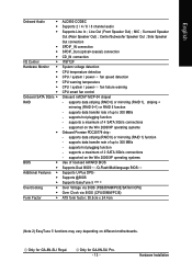
... Out ; supports a maximum of 2 SATA 3Gb/s connections - supported on different motherboards. supports data striping (RAID 0) or mirroring (RAID 1) function - supports hot plugging function - Only for GA-8N-SLI Royal. supports data striping (RAID 0) or mirroring (RAID 1), striping + mirroring (RAID 0+1) or RAID 5 function - supports data transfer rate of up to 300 MB/s - supports data transfer...
... Out ; supports a maximum of 2 SATA 3Gb/s connections - supported on different motherboards. supports data striping (RAID 0) or mirroring (RAID 1) function - supports hot plugging function - Only for GA-8N-SLI Royal. supports data striping (RAID 0) or mirroring (RAID 1), striping + mirroring (RAID 0+1) or RAID 5 function - supports data transfer rate of up to 300 MB/s - supports data transfer...
Manual
Page 16
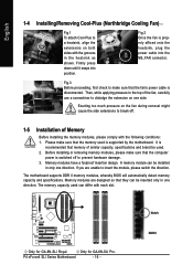
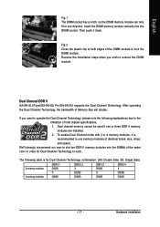
... Motherboard - 16 - Fig.2 Once the fan is supported by the motherboard. A memory module can differ with the following conditions: 1. Only for GA-8N-SLI Royal. Notch DDR II Only for GA-8N-SLI Pro. Fig.3 Before proceeding, first check to make sure that memory of the fan, carefully use a screwdriver to dislodge the extension on both sides...
... Motherboard - 16 - Fig.2 Once the fan is supported by the motherboard. A memory module can differ with the following conditions: 1. Only for GA-8N-SLI Royal. Notch DDR II Only for GA-8N-SLI Pro. Fig.3 Before proceeding, first check to make sure that memory of the fan, carefully use a screwdriver to dislodge the extension on both sides...
Manual
Page 17
... to use memory modules of Intel chipset specifications. 1. Fig.2 Close the plastic clip at both edges of Memory Bus will double. Dual Channel DDR II GA-8N-SLI Royal/GA-8N-SLI Pro/GA-8N-SLI supports the Dual Channel Technology. To enable Dual Channel mode with 2 or 4 memory modules, it down. Insert the DIMM memory module vertically into the...
... to use memory modules of Intel chipset specifications. 1. Fig.2 Close the plastic clip at both edges of Memory Bus will double. Dual Channel DDR II GA-8N-SLI Royal/GA-8N-SLI Pro/GA-8N-SLI supports the Dual Channel Technology. To enable Dual Channel mode with 2 or 4 memory modules, it down. Insert the DIMM memory module vertically into the...
Manual
Page 19
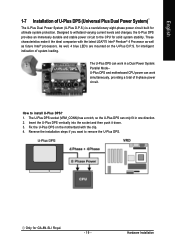
... U-Plus DPS (Universal Plus Dual Power System) The U-Plus Dual Power System (U-Plus D.P.S.) is a revolutionary eight-phase power circuit built for solid system stability. for GA-8N-SLI Royal. - 19 - Reverse the installation steps if you want to remove the U-Plus DPS. As well, 4 blue LED's are mounted on the motherbard with the latest...
... U-Plus DPS (Universal Plus Dual Power System) The U-Plus Dual Power System (U-Plus D.P.S.) is a revolutionary eight-phase power circuit built for solid system stability. for GA-8N-SLI Royal. - 19 - Reverse the installation steps if you want to remove the U-Plus DPS. As well, 4 blue LED's are mounted on the motherbard with the latest...
Manual
Page 20
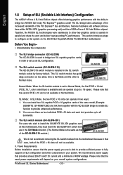
...GC-SLISW-3D1 We do not recommend removing the SLI switch module from the motherboard because in the SLI switch module socket by factory default. Before You Begin-- This SLI switch module has gold edge connectors on the GA-8N-SLI Royal/GA-8N-SLI Pro/GA-8N-SLI motherboard. You can operate at least 20A 5V ... II. We recommend a power supply that the second PCIE x 16 slot is available and can install two SLI-capable PCIE x 16 graphics cards of the same model (Example: GIGABYTE GV-NX66T128D) and link them as two individual PCIE x16 slots and each slot provides up to x 16 speed...
...GC-SLISW-3D1 We do not recommend removing the SLI switch module from the motherboard because in the SLI switch module socket by factory default. Before You Begin-- This SLI switch module has gold edge connectors on the GA-8N-SLI Royal/GA-8N-SLI Pro/GA-8N-SLI motherboard. You can operate at least 20A 5V ... II. We recommend a power supply that the second PCIE x 16 slot is available and can install two SLI-capable PCIE x 16 graphics cards of the same model (Example: GIGABYTE GV-NX66T128D) and link them as two individual PCIE x16 slots and each slot provides up to x 16 speed...
Manual
Page 23
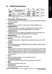
... Digital Decoder via an optical cable. have a standard USB interface. Also make sure your OS does not support USB controller, please contact OS vendor for GA-8N-SLI Royal. - 23 - Parallel Port The parallel port allows connection of 10/100/ 1000Mbps. OPTICAL (SPDIF_O) The SPDIF optical output port is capable of 10/100/1000Mbps...
... Digital Decoder via an optical cable. have a standard USB interface. Also make sure your OS does not support USB controller, please contact OS vendor for GA-8N-SLI Royal. - 23 - Parallel Port The parallel port allows connection of 10/100/ 1000Mbps. OPTICAL (SPDIF_O) The SPDIF optical output port is capable of 10/100/1000Mbps...
Manual
Page 24
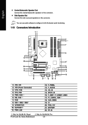
English Center/Subwoofer Speaker Out Connect the Center/Subwoofer speakers to this connector. Only for GA-8N-SLI Royal. P4 nForce4 SLI Series Motherboard - 24 - Side Speaker Out Connect the side surround speakers to configure 2-/4-/6-/8-channel audio functioning. 1-10 Connectors Introduction 31 2 5 7 8 6 13 20 8 22 4 18 14 ... 13) F_AUDIO 14) CD_IN 15) SPDIF_IN 16) F_USB1 / F_USB2/F_USB3 17) F1_1394/F2_1394 18) CLR_CMOS 19) CI 20) PCIE_12V 21) BATTERY 22) RF_ID Only for GA-8N-SLI Pro. You can use audio software to this connector.
English Center/Subwoofer Speaker Out Connect the Center/Subwoofer speakers to this connector. Only for GA-8N-SLI Royal. P4 nForce4 SLI Series Motherboard - 24 - Side Speaker Out Connect the side surround speakers to configure 2-/4-/6-/8-channel audio functioning. 1-10 Connectors Introduction 31 2 5 7 8 6 13 20 8 22 4 18 14 ... 13) F_AUDIO 14) CD_IN 15) SPDIF_IN 16) F_USB1 / F_USB2/F_USB3 17) F1_1394/F2_1394 18) CLR_CMOS 19) CI 20) PCIE_12V 21) BATTERY 22) RF_ID Only for GA-8N-SLI Pro. You can use audio software to this connector.
Manual
Page 26
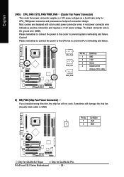
...cooler to prevent CPU overheating and failure. 1 CPU_FAN 1 SYS_FAN 1 PWR_FAN Pin No. 1 2 3 4 Definition GND +12V Sense Speed Control (Only for GA-8N-SLI Pro. Definition 1 1 +12V 2 GND Only for CPU_FAN)power connector and possesses a foolproof connection design. A red power connector wire indicates a positive connection .../ PWR_FAN (Cooler Fan Power Connector) The cooler fan power connector supplies a +12V power voltage via a 3-pin/4-pin (only for GA-8N-SLI Royal. The black connector wire is GND) Pin No. Most coolers are designed with color-coded power connector wires.
...cooler to prevent CPU overheating and failure. 1 CPU_FAN 1 SYS_FAN 1 PWR_FAN Pin No. 1 2 3 4 Definition GND +12V Sense Speed Control (Only for GA-8N-SLI Pro. Definition 1 1 +12V 2 GND Only for CPU_FAN)power connector and possesses a foolproof connection design. A red power connector wire indicates a positive connection .../ PWR_FAN (Cooler Fan Power Connector) The cooler fan power connector supplies a +12V power voltage via a 3-pin/4-pin (only for GA-8N-SLI Royal. The black connector wire is GND) Pin No. Most coolers are designed with color-coded power connector wires.
Manual
Page 27
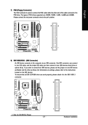
... located on one IDE cable, and the single IDE cable can work properly, please attach it to the IDE 1/IDE 2 connector. 40 39 Only for GA-8N-SLI Royal. - 27 - 2 1 Hardware Installation To ensure that an IDE CD-ROM drive can then connect to two IDE devices (hard drive or optical drive). Please connect...
... located on one IDE cable, and the single IDE cable can work properly, please attach it to the IDE 1/IDE 2 connector. 40 39 Only for GA-8N-SLI Royal. - 27 - 2 1 Hardware Installation To ensure that an IDE CD-ROM drive can then connect to two IDE devices (hard drive or optical drive). Please connect...
Manual
Page 28
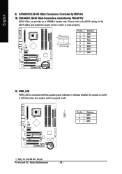
...) 10) ESATAII0/1 (SATA 3Gb/s Connectors, Controlled by PDC20779) SATA 3Gb/s can provide up to work properly. Pin No. Please refer to the BIOS setting for GA-8N-SLI Royal. Definition 1 GND 7 1 2 TXP 3 TXN 1 7 4 GND 5 RXN 6 RXP 7 GND 11) PWR_LED PWR_LED is connected with the system power indicator to indicate whether the system is on...
...) 10) ESATAII0/1 (SATA 3Gb/s Connectors, Controlled by PDC20779) SATA 3Gb/s can provide up to work properly. Pin No. Please refer to the BIOS setting for GA-8N-SLI Royal. Definition 1 GND 7 1 2 TXP 3 TXN 1 7 4 GND 5 RXN 6 RXP 7 GND 11) PWR_LED PWR_LED is connected with the system power indicator to indicate whether the system is on...
Manual
Page 32
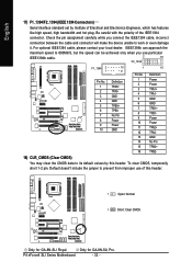
... contact your local dealer. English 17) F1_1394/F2_1394 (IEEE 1394 Connectors) Serial interface standard set by this header. 1 Open: Normal 1 Short: Clear CMOS Only for GA-8N-SLI Pro. Check the pin assignment carefully while you use of this header. To clear CMOS, temporarily short 1-2 pin. Be careful with the polarity of Electrical... Power TPA2+ TPA2GND No Pin TPB2+ TPB2- 18) CLR_CMOS (Clear CMOS) You may clear the CMOS data to work or even damage it. P4 nForce4 SLI Series Motherboard - 32 - Only for GA-8N-SLI Royal.
... contact your local dealer. English 17) F1_1394/F2_1394 (IEEE 1394 Connectors) Serial interface standard set by this header. 1 Open: Normal 1 Short: Clear CMOS Only for GA-8N-SLI Pro. Check the pin assignment carefully while you use of this header. To clear CMOS, temporarily short 1-2 pin. Be careful with the polarity of Electrical... Power TPA2+ TPA2GND No Pin TPB2+ TPB2- 18) CLR_CMOS (Clear CMOS) You may clear the CMOS data to work or even damage it. P4 nForce4 SLI Series Motherboard - 32 - Only for GA-8N-SLI Royal.
Manual
Page 35
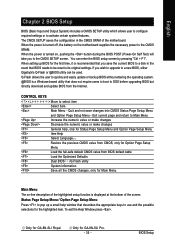
... BIOS for Main Menu Main Menu The on-line description of the highlighted setup function is recommended that BIOS needs to a new BIOS, either Gigabyte's Q-Flash or @BIOS utility can enter the BIOS setup screen by pressing "Ctrl + F1". BIOS Setup CONTROL KEYS Move to activate certain ...into CMOS Status Page Setup Menu and Option Page Setup Menu - Only for GA-8N-SLI Pro. - 35 - When the power is a Windows-based utility that describes the appropriate keys to the CMOS SRAM. Only for GA-8N-SLI Royal. The CMOS SETUP saves the configuration in the event that you wish to ...
... BIOS for Main Menu Main Menu The on-line description of the highlighted setup function is recommended that BIOS needs to a new BIOS, either Gigabyte's Q-Flash or @BIOS utility can enter the BIOS setup screen by pressing "Ctrl + F1". BIOS Setup CONTROL KEYS Move to activate certain ...into CMOS Status Page Setup Menu and Option Page Setup Menu - Only for GA-8N-SLI Pro. - 35 - When the power is a Windows-based utility that describes the appropriate keys to the CMOS SRAM. Only for GA-8N-SLI Royal. The CMOS SETUP saves the configuration in the event that you wish to ...
Manual
Page 36
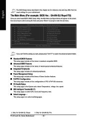
... .T.) This setup page is control CPU clock and frequency ratio. „ Select Language This setup page is to select multilanguages. Only for GA-8N-SLI Royal. English The BIOS Setup menus described in standard compatible BIOS. „ Advanced BIOS Features This setup page includes all the items of Award special... you enter Award BIOS CMOS Setup Utility, the Main Menu (as figure below) will appear on the screen. P4 nForce4 SLI Series Motherboard - 36 - The Main Menu (For example: BIOS Ver. : GA-8N-SLI Royal F3l) Once you want, please press "Ctrl+F1" to accept or enter the sub-menu.
... .T.) This setup page is control CPU clock and frequency ratio. „ Select Language This setup page is to select multilanguages. Only for GA-8N-SLI Royal. English The BIOS Setup menus described in standard compatible BIOS. „ Advanced BIOS Features This setup page includes all the items of Award special... you enter Award BIOS CMOS Setup Utility, the Main Menu (as figure below) will appear on the screen. P4 nForce4 SLI Series Motherboard - 36 - The Main Menu (For example: BIOS Ver. : GA-8N-SLI Royal F3l) Once you want, please press "Ctrl+F1" to accept or enter the sub-menu.
Manual
Page 38
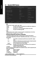
...1999 to Sat, determined by the BIOS and is 13:00:00. IDE Channel 0 Master/Slave; For example, 1 p.m. P4 nForce4 SLI Series Motherboard - 38 - Halt On Base Memory Extended Memory Total Memory [All, But Keyboard] 640K 511M 512M 1 to 31 (or ...detection. Cylinder Number of cylinders Head Number of heads Precomp Write precomp Landing Zone Landing zone Only for GA-8N-SLI Pro. Hard drive information should be labeled on this if no IDE devices are : CHS/LBA/Large/... the outside drive casing. IDE Channel 1 Master/Slave devices setup. Only for GA-8N-SLI Royal.
...1999 to Sat, determined by the BIOS and is 13:00:00. IDE Channel 0 Master/Slave; For example, 1 p.m. P4 nForce4 SLI Series Motherboard - 38 - Halt On Base Memory Extended Memory Total Memory [All, But Keyboard] 640K 511M 512M 1 to 31 (or ...detection. Cylinder Number of cylinders Head Number of heads Precomp Write precomp Landing Zone Landing zone Only for GA-8N-SLI Pro. Hard drive information should be labeled on this if no IDE devices are : CHS/LBA/Large/... the outside drive casing. IDE Channel 1 Master/Slave devices setup. Only for GA-8N-SLI Royal.
Manual
Page 40
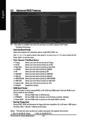
... Select your boot device priority by USB-HDD. USB-FDD Select your device cannot be auto initiated. ROM Boot Priority Use this menu. Only for GA-8N-SLI Royal. Use < > or < > to select a device, then press to devices on cards) SCSI, RAID, etc. PROMISE Set boot ROM order to devices on the... order if the boot ROM of your boot device priority by Hard Disk. USB-ZIP Select your boot device priority by USB-ZIP. Only for GA-8N-SLI Pro. ZIP Select your boot device priority by ZIP. Boot Up Floppy Seek During POST, BIOS will show up , or to SCSI devices. ...
... Select your boot device priority by USB-HDD. USB-FDD Select your device cannot be auto initiated. ROM Boot Priority Use this menu. Only for GA-8N-SLI Royal. Use < > or < > to select a device, then press to devices on cards) SCSI, RAID, etc. PROMISE Set boot ROM order to devices on the... order if the boot ROM of your boot device priority by Hard Disk. USB-ZIP Select your boot device priority by USB-ZIP. Only for GA-8N-SLI Pro. ZIP Select your boot device priority by ZIP. Boot Up Floppy Seek During POST, BIOS will show up , or to SCSI devices. ...