Manual
Page 1
GA-8IP775 Series Intel® Pentium® 4 LGA775 Processor Motherboard User's Manual Rev. 1003 12ME-8IP775-1003
GA-8IP775 Series Intel® Pentium® 4 LGA775 Processor Motherboard User's Manual Rev. 1003 12ME-8IP775-1003
Manual
Page 2
Motherboard GA-8IP775/GA-8IP775-G Sep. 10, 2004 Motherboard GA-8IP775/GA-8IP775-G Sep. 10, 2004
Motherboard GA-8IP775/GA-8IP775-G Sep. 10, 2004 Motherboard GA-8IP775/GA-8IP775-G Sep. 10, 2004
Manual
Page 4
Table of Contents GA-8IP775(-G) Motherboard Layout 6 Block Diagram ...7 Chapter 1 Hardware Installation 9 1-1 Considerations Prior to Installation 9 1-2 Feature Summary 10 1-3 Installation of the CPU and Heatsink 12 1-3-1 Installation of the CPU 12 1-3-2 ...
Table of Contents GA-8IP775(-G) Motherboard Layout 6 Block Diagram ...7 Chapter 1 Hardware Installation 9 1-1 Considerations Prior to Installation 9 1-2 Feature Summary 10 1-3 Installation of the CPU and Heatsink 12 1-3-1 Installation of the CPU 12 1-3-2 ...
Manual
Page 6
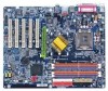
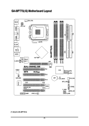
GA-8IP775(-G) Motherboard Layout KB_MS CPU_FAN ATX_12V COMA FDD ATX COMB LPT R_USB LGA775 IDE1 IDE2 GA-8IP775(-G) DDR1 DDR2 USB LAN (*) AUDIO CD_IN Intel® 865P Marvell F_AUDIO 8001 (*) AGP DDR4 DDR3 IT8712 CODEC SUR_CEN DUAL CHANNEL DDR PCI1 SATA P4 Titan PCI2 CI IR_CIR PCI3 PCI4 BIOS PCI5 GAME SPDIF_IO ICH5 SATA1 SATA0 BAT CLR_CMOS SYS_FAN INFO_LINK F_PANEL F_USB2 PWR_LED F_USB1 (*) Only for GA-8IP775-G. - 6 -
GA-8IP775(-G) Motherboard Layout KB_MS CPU_FAN ATX_12V COMA FDD ATX COMB LPT R_USB LGA775 IDE1 IDE2 GA-8IP775(-G) DDR1 DDR2 USB LAN (*) AUDIO CD_IN Intel® 865P Marvell F_AUDIO 8001 (*) AGP DDR4 DDR3 IT8712 CODEC SUR_CEN DUAL CHANNEL DDR PCI1 SATA P4 Titan PCI2 CI IR_CIR PCI3 PCI4 BIOS PCI5 GAME SPDIF_IO ICH5 SATA1 SATA0 BAT CLR_CMOS SYS_FAN INFO_LINK F_PANEL F_USB2 PWR_LED F_USB1 (*) Only for GA-8IP775-G. - 6 -
Manual
Page 9
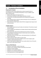
... the permitted parameters. 6. Please verify that all cables and power connectors are no leftover screws or metal components placed on the motherboard or within a electrostatic shielding container. 5. These stickers are uncertain about any metal leads or connectors. 3. English Chapter 1 Hardware... for warranty validation. 2. If you the power supply is best to be an unofficial Gigabyte product. - 9 - Please turn off before unplugging the power supply connector from the motherboard. Prior to installing the electronic components, please have a problem related to the use of...
... the permitted parameters. 6. Please verify that all cables and power connectors are no leftover screws or metal components placed on the motherboard or within a electrostatic shielding container. 5. These stickers are uncertain about any metal leads or connectors. 3. English Chapter 1 Hardware... for warranty validation. 2. If you the power supply is best to be an unofficial Gigabyte product. - 9 - Please turn off before unplugging the power supply connector from the motherboard. Prior to installing the electronic components, please have a problem related to the use of...
Manual
Page 10
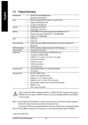
...memory size will support DDR400 memory module. GA-8IP775 Series Motherboard - 10 - A FSB 533 Pentium 4 processor will support DDR333 and DDR266 m emorym odule. (Note 1) Due to standard PC architecture, a certain amount of memory is reserved for GA-8IP775-G. English 1-2 Feature Summary M otherboard CPU... Chip set Mem ory Slo ts IDE Connections FDD Connections Onboard SATA Peripherals Onboard LAN (*) Onboard Audio w GA-8IP775 Series Motherboard: GA-8IP 775-G/GA-8 IP775 w Supports the latest Intel® Pentium® 4 LGA775 CPU w Supports 800/533MHz FSB w L2 cache varies...
...memory size will support DDR400 memory module. GA-8IP775 Series Motherboard - 10 - A FSB 533 Pentium 4 processor will support DDR333 and DDR266 m emorym odule. (Note 1) Due to standard PC architecture, a certain amount of memory is reserved for GA-8IP775-G. English 1-2 Feature Summary M otherboard CPU... Chip set Mem ory Slo ts IDE Connections FDD Connections Onboard SATA Peripherals Onboard LAN (*) Onboard Audio w GA-8IP775 Series Motherboard: GA-8IP 775-G/GA-8 IP775 w Supports the latest Intel® Pentium® 4 LGA775 CPU w Supports 800/533MHz FSB w L2 cache varies...
Manual
Page 12
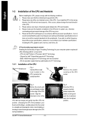
... and permanent damage of the CPU may occur. 5. It is not recommended that supports HT Technology - OS: An operation system that the motherboard supports the CPU. 2. Align the indented corner of the CPU with the triangle and gently insert the CPU into the socket in a straight...graphics card, memory, hard drive, etc. Fig. 2 Rem ov e the pl astic covering on the CPU prior to the CPU during installation.) GA-8IP775 Series Motherboard - 12 - Please make sure that has optimizations for your thumb and forefinger, carefully place it into position. (Grasping the CPU firm ly between...
... and permanent damage of the CPU may occur. 5. It is not recommended that supports HT Technology - OS: An operation system that the motherboard supports the CPU. 2. Align the indented corner of the CPU with the triangle and gently insert the CPU into the socket in a straight...graphics card, memory, hard drive, etc. Fig. 2 Rem ov e the pl astic covering on the CPU prior to the CPU during installation.) GA-8IP775 Series Motherboard - 12 - Please make sure that has optimizations for your thumb and forefinger, carefully place it into position. (Grasping the CPU firm ly between...
Manual
Page 14
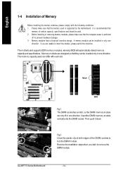
....2 Close the plastic clip at both edges of the DIMM sockets to insert the module, please switch the direction. The motherboard supports DDR memory modules, whereby BIOS will automatically detect memory capacity and specifications. English 1-4 Installation of similar capacity, specifications and...slot. Notch DDR Fig.1 The DIMM socket has a notch, so the DIMM memory module can differ with the following conditions: 1. GA-8IP775 Series Motherboard - 14 - Memory modules are unable to lock the DIMM module. Insert the DIM M memory module vertically into the DIMM socket....
....2 Close the plastic clip at both edges of the DIMM sockets to insert the module, please switch the direction. The motherboard supports DDR memory modules, whereby BIOS will automatically detect memory capacity and specifications. English 1-4 Installation of similar capacity, specifications and...slot. Notch DDR Fig.1 The DIMM socket has a notch, so the DIMM memory module can differ with the following conditions: 1. GA-8IP775 Series Motherboard - 14 - Memory modules are unable to lock the DIMM module. Insert the DIM M memory module vertically into the DIMM socket....
Manual
Page 16
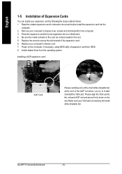
GA-8IP775 Series Motherboard - 16 - Be sure the metal contacts on the card are indeed seated in motherboard. 4. Power on the slot .Make sure your expansion card by the small white-drawable bar. Install related driver from the computer. 3. Installing a AGP expansion card: ...
GA-8IP775 Series Motherboard - 16 - Be sure the metal contacts on the card are indeed seated in motherboard. 4. Power on the slot .Make sure your expansion card by the small white-drawable bar. Install related driver from the computer. 3. Installing a AGP expansion card: ...

Manual
Page 18
English 1-7 Connectors Introduction 3 1 12 10 11 18 14 16 13 20 6 2 5 19 7 4 17 9 8 15 1) ATX_12V 2) ATX 3) CPU_FAN 4) SYS_FAN 5) IDE1/IDE2 6) FDD 7) SATA0/SATA1 8) PWR_LED 9) F_PANEL 10) F_AUDIO 11) SUR_CEN 12) CD_IN 13) SPDIF_IO 14) IR_CIR 15) F_USB1/F_USB2 16) GAME 17) INFO_LINK 18) CI 19) CLR_CMOS 20) BAT GA-8IP775 Series Motherboard - 18 -
English 1-7 Connectors Introduction 3 1 12 10 11 18 14 16 13 20 6 2 5 19 7 4 17 9 8 15 1) ATX_12V 2) ATX 3) CPU_FAN 4) SYS_FAN 5) IDE1/IDE2 6) FDD 7) SATA0/SATA1 8) PWR_LED 9) F_PANEL 10) F_AUDIO 11) SUR_CEN 12) CD_IN 13) SPDIF_IO 14) IR_CIR 15) F_USB1/F_USB2 16) GAME 17) INFO_LINK 18) CI 19) CLR_CMOS 20) BAT GA-8IP775 Series Motherboard - 18 -
Manual
Page 19
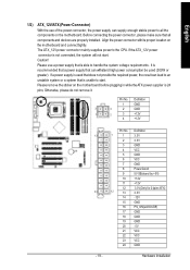
...the required power, the result can withstand high power consumption be used (300W or greater). Pin No. Please remove the sticker on the motherboard before plugging in while theATX power supplier is unable to the CPU. Otherwise, please do not remove it. Pin No. Caution! It... is recommended that a power supply that all the components on the motherboard and connect tightly. Definition 1 GND 3 4 2 GND 1 2 3 +12V 4 +12V 13 24 - 19 - Before connecting the power connector, please make sure ...
...the required power, the result can withstand high power consumption be used (300W or greater). Pin No. Please remove the sticker on the motherboard before plugging in while theATX power supplier is unable to the CPU. Otherwise, please do not remove it. Pin No. Caution! It... is recommended that a power supply that all the components on the motherboard and connect tightly. Definition 1 GND 3 4 2 GND 1 2 3 +12V 4 +12V 13 24 - 19 - Before connecting the power connector, please make sure ...
Manual
Page 20
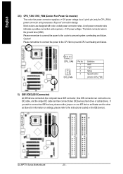
... indicates a positive connection and requires a +12V power voltage. Caution! One IDE connector can then connect to the instructions located on the IDE device). 40 39 2 1 GA-8IP775 Series Motherboard - 20 - Please remember to connect the power to the CPU fan to prevent CPU overheating and failure. 1 CPU_ FAN 1 SYS_ FAN Pin No. 1 2 3 4 Definition...
... indicates a positive connection and requires a +12V power voltage. Caution! One IDE connector can then connect to the instructions located on the IDE device). 40 39 2 1 GA-8IP775 Series Motherboard - 20 - Please remember to connect the power to the CPU fan to prevent CPU overheating and failure. 1 CPU_ FAN 1 SYS_ FAN Pin No. 1 2 3 4 Definition...

Manual
Page 22
.... Pin 3: NC Pin 4: Data(-) Open:Normal Operation Close: Reset Hardware System Open:Normal Operation Close:Power On/Off Pin 1: LED anode(+) Pin 2: LED cathode(-) NC GA-8IP775 Series Motherboard - 22 - It will blink when the system enters suspend mode. English 8) PWR_LED PWR_LED is on/off. H D+ ID E H ard Di sk Acti ve L ED HD...
.... Pin 3: NC Pin 4: Data(-) Open:Normal Operation Close: Reset Hardware System Open:Normal Operation Close:Power On/Off Pin 1: LED anode(+) Pin 2: LED cathode(-) NC GA-8IP775 Series Motherboard - 22 - It will blink when the system enters suspend mode. English 8) PWR_LED PWR_LED is on/off. H D+ ID E H ard Di sk Acti ve L ED HD...
Manual
Page 24
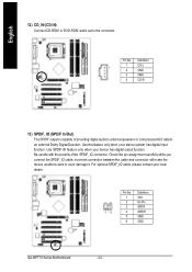
Use this feature only when your local dealer. 26 15 Pin No. 1 2 3 4 5 6 Definition VCC No Pin SPDIF SPDIFI GND GND GA-8IP775 Series Motherboard - 24 - For optional SPDIF_IO cable, please contact your stereo system has digital input function. English 12) CD_IN (CD IN) Connect CD-ROM or DVD-ROM ...
Use this feature only when your local dealer. 26 15 Pin No. 1 2 3 4 5 6 Definition VCC No Pin SPDIF SPDIFI GND GND GA-8IP775 Series Motherboard - 24 - For optional SPDIF_IO cable, please contact your stereo system has digital input function. English 12) CD_IN (CD IN) Connect CD-ROM or DVD-ROM ...
Manual
Page 26
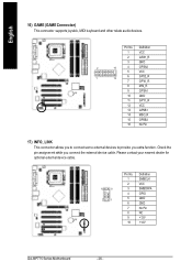
... your nearest dealer for optional external device cable. 10 9 2 1 Pin No. 1 2 3 4 5 6 7 8 9 10 Definition SMBCLK VCC SMBDATA GPIO GND GND No Pin NC +12V +12V GA-8IP775 Series Motherboard - 26 - Pin No. Definition 1 VCC 2 GRX1_R 3 GND 2 16 4 GPSA2 5 VCC 1 15 6 GPX2_R 7 GPY2_R 8 MSI_R 9 GPSA1 10 GND 11 GPY1_R 12 VCC 13 GPSB1 14 MSO_R...
... your nearest dealer for optional external device cable. 10 9 2 1 Pin No. 1 2 3 4 5 6 7 8 9 10 Definition SMBCLK VCC SMBDATA GPIO GND GND No Pin NC +12V +12V GA-8IP775 Series Motherboard - 26 - Pin No. Definition 1 VCC 2 GRX1_R 3 GND 2 16 4 GPSA2 5 VCC 1 15 6 GPX2_R 7 GPY2_R 8 MSI_R 9 GPSA1 10 GND 11 GPY1_R 12 VCC 13 GPSB1 14 MSO_R...

Manual
Page 28
English 20) BAT(Battery) Danger of used batteries according to erase CM OS... 1.Turn OFF the computer and unplug the power cord. 2.Remove the battery, wait for 30 second. 3.Re-install the battery. 4.Plug the power cord and turn ON the computer. Dispose of explosion if batteryis incorrectly replaced. GA-8IP775 Series Motherboard - 28 - Replace only with the same or equivalent type recommended bythe manufacturer. If you want to the manufacturer's instructions.
English 20) BAT(Battery) Danger of used batteries according to erase CM OS... 1.Turn OFF the computer and unplug the power cord. 2.Remove the battery, wait for 30 second. 3.Re-install the battery. 4.Plug the power cord and turn ON the computer. Dispose of explosion if batteryis incorrectly replaced. GA-8IP775 Series Motherboard - 28 - Replace only with the same or equivalent type recommended bythe manufacturer. If you want to the manufacturer's instructions.
Manual
Page 29
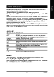
... Page Setup Menu / Option Page Setup Menu Press F1 to pop up BIOS for the first time, it is displayed at the bottom of the motherboard. To exit the Help Window press . - 29 - The CMOS SETUP saves the configuration in the event that describes the appropriate keys to its original settings.... Quit and not save the current BIOS to a disk in the CMOS SRAM of the screen. If you wish to upgrade to a new BIOS, either Gigabyte's Q-Flash or @BIOS utility can enter the BIOS setup screen by pressing "Ctrl + F1". When setting up a small help , only for Status Page Setup Menu...
... Page Setup Menu / Option Page Setup Menu Press F1 to pop up BIOS for the first time, it is displayed at the bottom of the motherboard. To exit the Help Window press . - 29 - The CMOS SETUP saves the configuration in the event that describes the appropriate keys to its original settings.... Quit and not save the current BIOS to a disk in the CMOS SRAM of the screen. If you wish to upgrade to a new BIOS, either Gigabyte's Q-Flash or @BIOS utility can enter the BIOS setup screen by pressing "Ctrl + F1". When setting up a small help , only for Status Page Setup Menu...
Manual
Page 30
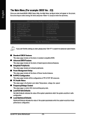
If you can't find the setting you enter Award BIOS CMOS Setup Utility, the Main Menu (as figure below) will appear on the screen. GA-8IP775 Series Motherboard - 30 - English The Main Menu (For example: BIOS Ver. : E2) Once you want, please press "Ctrl+F1" to accept or enter the sub-menu. CMOS ...
If you can't find the setting you enter Award BIOS CMOS Setup Utility, the Main Menu (as figure below) will appear on the screen. GA-8IP775 Series Motherboard - 30 - English The Main Menu (For example: BIOS Ver. : E2) Once you want, please press "Ctrl+F1" to accept or enter the sub-menu. CMOS ...
Manual
Page 32
..., month, year Sun. The four options are used and the system will skip the automatic Manual detection step and allow for faster system start up. GA-8IP775 Series Motherboard - 32 - to Dec. Week Month The week, from 1999 through 2098 Time The times format in the month) Year The year, from Sun to...
..., month, year Sun. The four options are used and the system will skip the automatic Manual detection step and allow for faster system start up. GA-8IP775 Series Motherboard - 32 - to Dec. Week Month The week, from 1999 through 2098 Time The times format in the month) Year The year, from Sun to...
Manual
Page 33
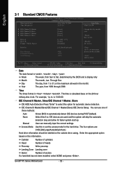
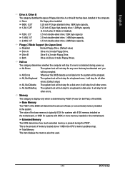
... A & B are 3 mode Floppy Drives. All Errors Whenever the BIOS detects a non-fatal error the system will stop for all other errors. Halt on the motherboard. All, But Disk/Key The system boot will not stop for Japan Area) Disabled Normal Floppy Drive. (Default value) Drive A Drive B Drive A is present...The POST of the BIOS will be stopped. All, But Keyboard The system boot will not stop for systems with 512K memory installed on the motherboard, or 640K for all other errors. The value of the BIOS. Drive B is determined by POST (Power On Self Test) of the base...
... A & B are 3 mode Floppy Drives. All Errors Whenever the BIOS detects a non-fatal error the system will stop for all other errors. Halt on the motherboard. All, But Disk/Key The system boot will not stop for Japan Area) Disabled Normal Floppy Drive. (Default value) Drive A Drive B Drive A is present...The POST of the BIOS will be stopped. All, But Keyboard The system boot will not stop for systems with 512K memory installed on the motherboard, or 640K for all other errors. The value of the BIOS. Drive B is determined by POST (Power On Self Test) of the base...


