Manual
Page 4
... Heatsink 11 1-3-1 Installation of the CPU 11 1-3-2 Installation of the Heatsink 12 1-4 Installation of Memory 13 1-5 Installation of Expansion Cards 15 1-6 I/O Back Panel Introduction 16 1-7 Connectors Introduction 17 Chapter 2 BIOS Setup 27 The Main Menu (For example: BIOS Ver. : E4 28 2-1 Standard CMOS Features 30 2-2 Advanced BIOS Features 32 2-3 Integrated Peripherals 34 2-4 Power Management Setup 37 2-5 PnP/PCI Configurations 38 2-6 PC Health Status 39 2-7 Frequency/Voltage Control 40 2-8 Load Fail-Safe Defaults 41 2-9 Load Optimized Defaults 41 2-10 Set Supervisor/User...
... Heatsink 11 1-3-1 Installation of the CPU 11 1-3-2 Installation of the Heatsink 12 1-4 Installation of Memory 13 1-5 Installation of Expansion Cards 15 1-6 I/O Back Panel Introduction 16 1-7 Connectors Introduction 17 Chapter 2 BIOS Setup 27 The Main Menu (For example: BIOS Ver. : E4 28 2-1 Standard CMOS Features 30 2-2 Advanced BIOS Features 32 2-3 Integrated Peripherals 34 2-4 Power Management Setup 37 2-5 PnP/PCI Configurations 38 2-6 PC Health Status 39 2-7 Frequency/Voltage Control 40 2-8 Load Fail-Safe Defaults 41 2-9 Load Optimized Defaults 41 2-10 Set Supervisor/User...
Manual
Page 6
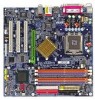
IDE1 GA-8I865GM-775/GA-8I865GMF-775 Motherboard Layout KB_MS ATX_12V LGA775 CPU_FAN ATX FDD COMA GA-8I865GM-775 (or GA-8I865GMF-775*) DDR1 DDR2 DDR3 DDR4 IDE2 LPT VGA R_USB USB LAN F_AUDIO LPC47M997 IR AUDIO BIOS SPDIF Marvell 8001 CODEC CD_IN AGP COMB Intel 865G BAT PCI1 PCI2 TSB43AB23* PCI3 F2_1394* F1_1394* Intel ICH5 SATA1 SATA0 F_USB1 F_USB2 PWR_LED F_PANEL CLR_CMOS SYS_FAN * Only for GA-8I865GMF-775. - 6 -
IDE1 GA-8I865GM-775/GA-8I865GMF-775 Motherboard Layout KB_MS ATX_12V LGA775 CPU_FAN ATX FDD COMA GA-8I865GM-775 (or GA-8I865GMF-775*) DDR1 DDR2 DDR3 DDR4 IDE2 LPT VGA R_USB USB LAN F_AUDIO LPC47M997 IR AUDIO BIOS SPDIF Marvell 8001 CODEC CD_IN AGP COMB Intel 865G BAT PCI1 PCI2 TSB43AB23* PCI3 F2_1394* F1_1394* Intel ICH5 SATA1 SATA0 F_USB1 F_USB2 PWR_LED F_PANEL CLR_CMOS SYS_FAN * Only for GA-8I865GMF-775. - 6 -
Manual
Page 10
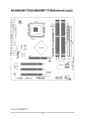
...; 1 front audio connector Š 1 IR connector Š 1 PS/2 keyboard port Š 1 PS/2 mouse port Š Onboard Marvell 8001 chip (10/100/1000 Mbit) Š 1 RJ 45 port Š ADI AD1888 CODEC Š Supports 2 / 4 / 6 channel audio Š Supports Line In (Rear Speaker Out) ; GA-8I865GM(F)-775 Motherboard - 10 - English 1-2 Feature Summary Motherboard CPU Chipset Memory Slots IDE Connections FDD Connections Onboard SATA Peripherals Onboard LAN Onboard Audio I/O Control Hardware Monitor BIOS Additional Features Form Factor Š GA-8I865GM-775 or GA-8I865GMF-775 Š Supports the...
...; 1 front audio connector Š 1 IR connector Š 1 PS/2 keyboard port Š 1 PS/2 mouse port Š Onboard Marvell 8001 chip (10/100/1000 Mbit) Š 1 RJ 45 port Š ADI AD1888 CODEC Š Supports 2 / 4 / 6 channel audio Š Supports Line In (Rear Speaker Out) ; GA-8I865GM(F)-775 Motherboard - 10 - English 1-2 Feature Summary Motherboard CPU Chipset Memory Slots IDE Connections FDD Connections Onboard SATA Peripherals Onboard LAN Onboard Audio I/O Control Hardware Monitor BIOS Additional Features Form Factor Š GA-8I865GM-775 or GA-8I865GMF-775 Š Supports the...
Manual
Page 20
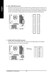
... 6 RXP 7 GND GA-8I865GM(F)-775 Motherboard - 20 - One IDE connector can connect to one IDE device as Master and the other as Slave (for the Serial ATA and install the proper driver in order to two IDE devices (hard drive or optical drive). Please refer to the BIOS setting for information on settings, please refer to the instructions located on one IDE cable, and the single IDE cable can provide 150MB/s transfer rate. Pin No. If...
... 6 RXP 7 GND GA-8I865GM(F)-775 Motherboard - 20 - One IDE connector can connect to one IDE device as Master and the other as Slave (for the Serial ATA and install the proper driver in order to two IDE devices (hard drive or optical drive). Please refer to the BIOS setting for information on settings, please refer to the instructions located on one IDE cable, and the single IDE cable can provide 150MB/s transfer rate. Pin No. If...

Manual
Page 22
RESRES+ NC Reset Switch IDE Hard Disk Active LED HD (IDE Hard Disk Active LED) SPEAK (Speaker Connector) RES (Reset Switch) PW (Power Switch) MSG (Message LED/Power/Sleep LED) NC Pin 1: LED anode(+) Pin 2: LED cathode(-) Pin 1: VCC(+) Pin 2- Pin 3: NC Pin 4: Data(-) Open: Normal Operation Close: Reset Hardware System Open: Normal Operation Close: Power On/Off Pin 1: LED anode(+) Pin 2: LED cathode(-) NC GA-8I865GM(F)-775 Motherboard - 22 - of your chassis front panel to the F_PANEL connector according to the pin assignment below. PW+ PWSPEAK+ SPEAK- 2 20 1 19 HD+ HD...
RESRES+ NC Reset Switch IDE Hard Disk Active LED HD (IDE Hard Disk Active LED) SPEAK (Speaker Connector) RES (Reset Switch) PW (Power Switch) MSG (Message LED/Power/Sleep LED) NC Pin 1: LED anode(+) Pin 2: LED cathode(-) Pin 1: VCC(+) Pin 2- Pin 3: NC Pin 4: Data(-) Open: Normal Operation Close: Reset Hardware System Open: Normal Operation Close: Power On/Off Pin 1: LED anode(+) Pin 2: LED cathode(-) NC GA-8I865GM(F)-775 Motherboard - 22 - of your chassis front panel to the F_PANEL connector according to the pin assignment below. PW+ PWSPEAK+ SPEAK- 2 20 1 19 HD+ HD...

Manual
Page 28
... 28 - CMOS Setup Utility-Copyright (C) 1984-2004 Award Software ` Standard CMOS Features ` Advanced BIOS Features ` Integrated Peripherals ` Power Management Setup ` PnP/PCI Configurations ` PC Health Status ` Frequency/Voltage Control ESC: Quit F8: Q-Flash Load Fail-Safe Defaults Load Optimized Defaults Set Supervisor Password Set User Password Save & Exit Setup Exit Without Saving KLJI: Select Item F10: Save & Exit Setup Time, Date, Hard Disk Type... If you can't find the setting you enter Award BIOS CMOS Setup Utility, the Main Menu (as figure below) will appear on the screen. English...
... 28 - CMOS Setup Utility-Copyright (C) 1984-2004 Award Software ` Standard CMOS Features ` Advanced BIOS Features ` Integrated Peripherals ` Power Management Setup ` PnP/PCI Configurations ` PC Health Status ` Frequency/Voltage Control ESC: Quit F8: Q-Flash Load Fail-Safe Defaults Load Optimized Defaults Set Supervisor Password Set User Password Save & Exit Setup Exit Without Saving KLJI: Select Item F10: Save & Exit Setup Time, Date, Hard Disk Type... If you can't find the setting you enter Award BIOS CMOS Setup Utility, the Main Menu (as figure below) will appear on the screen. English...
Manual
Page 30
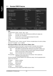
... to set the access mode for automatic device detection. is calculated base on the outside drive casing. You can manually input the correct settings. Manual User can use one of sectors If a hard disk has not been installed, select NONE and press . Halt On Base Memory Extended Memory Total Memory [All, But Keyboard] 640K 239M 240M 1 to automatically detect IDE devices during POST. (Default value) None Select this information. Enter the appropriate option based...
... to set the access mode for automatic device detection. is calculated base on the outside drive casing. You can manually input the correct settings. Manual User can use one of sectors If a hard disk has not been installed, select NONE and press . Halt On Base Memory Extended Memory Total Memory [All, But Keyboard] 640K 239M 240M 1 to automatically detect IDE devices during POST. (Default value) None Select this information. Enter the appropriate option based...
Manual
Page 32
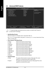
...(F)-775 Motherboard - 32 - USB-FDD Select your boot device priority by LAN. Disabled Select your boot device priority by ZIP. LAN Select your boot device priority by Hard Disk. English 2-2 Advanced BIOS Features CMOS Setup Utility-Copyright (C) 1984-2004 Award Software Advanced BIOS Features ` Hard Disk Boot Priority First Boot Device Second Boot Device Third Boot Device Password Check # CPU Hyper-Threading Limit CPUID Max. Use < > or < > to select a device, then press to move it up when you install the Intel® Pentium® 4 processor with HT Technology. Hard Disk...
...(F)-775 Motherboard - 32 - USB-FDD Select your boot device priority by LAN. Disabled Select your boot device priority by ZIP. LAN Select your boot device priority by Hard Disk. English 2-2 Advanced BIOS Features CMOS Setup Utility-Copyright (C) 1984-2004 Award Software Advanced BIOS Features ` Hard Disk Boot Priority First Boot Device Second Boot Device Third Boot Device Password Check # CPU Hyper-Threading Limit CPUID Max. Use < > or < > to select a device, then press to move it up when you install the Intel® Pentium® 4 processor with HT Technology. Hard Disk...
Manual
Page 34
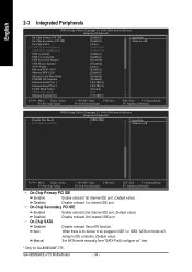
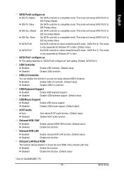
... PCI IDE Enabled Enable onboard 2nd channel IDE port. (Default value) Disabled Disable onboard 2nd channel IDE port. Auto When there is no device to be plugged in IDE1 or IDE2, SATA controller will remap to IDE controller. (Default value) Manual Set SATA mode manually from "SATA Port0 configure as USB Controller USB 2.0 Controller USB Keyboard Support USB Mouse Support AC97 Audio Onboard H/W 1394* Onboard H/W LAN Onboard LAN Boot ROM POWER ON Function Onboard Serial Port 1 Onboard Serial Port 2 UART Mode Select x UR2 Duplex Mode Onboard Parallel Port [Enabled] [Enabled] [Auto] SATA...
... PCI IDE Enabled Enable onboard 2nd channel IDE port. (Default value) Disabled Disable onboard 2nd channel IDE port. Auto When there is no device to be plugged in IDE1 or IDE2, SATA controller will remap to IDE controller. (Default value) Manual Set SATA mode manually from "SATA Port0 configure as USB Controller USB 2.0 Controller USB Keyboard Support USB Mouse Support AC97 Audio Onboard H/W 1394* Onboard H/W LAN Onboard LAN Boot ROM POWER ON Function Onboard Serial Port 1 Onboard Serial Port 2 UART Mode Select x UR2 Duplex Mode Onboard Parallel Port [Enabled] [Enabled] [Auto] SATA...
Manual
Page 35
... Set SATA controller to native mode(Serial ATA mode - SATA Port0 Set SATA controller to compatible mode. SATA Port 0). SATA Port1 configure as The setting depends on "SATA Port0 configure as IDE Pri. Disabled Disable USB keyboard support. (Default value) USB Mouse Support Enabled Enable USB mouse support. Onboard LAN Boot ROM This function decide whether to compatible mode. IDE Pri. IDE Sec. Slave Set SATA controller to invoke the boot ROM of the onboard LAN chip. USB 2.0 Controller You can disable this function. Onboard H/W LAN Enabled Enable onboard H/W LAN...
... Set SATA controller to native mode(Serial ATA mode - SATA Port0 Set SATA controller to compatible mode. SATA Port 0). SATA Port1 configure as The setting depends on "SATA Port0 configure as IDE Pri. Disabled Disable USB keyboard support. (Default value) USB Mouse Support Enabled Enable USB mouse support. Onboard LAN Boot ROM This function decide whether to compatible mode. IDE Pri. IDE Sec. Slave Set SATA controller to invoke the boot ROM of the onboard LAN chip. USB 2.0 Controller You can disable this function. Onboard H/W LAN Enabled Enable onboard H/W LAN...

Manual
Page 37
... will blink. (Default value) Dual/OFF In standby mode(S1): a. PME Event Wake Up This feature requires an ATX power supply that provides at least 1A on the LAN can awake the system from any suspend state. b. Disabled Disable this function. BIOS Setup Power LED in "On" state. Enabled Enable Modem Ring On / Wake On LAN function. (Default value) - 37 - English 2-4 Power Management Setup CMOS Setup Utility-Copyright (C) 1984-2004 Award Software Power Management Setup ACPI Suspend Type Power LED in S1...
... will blink. (Default value) Dual/OFF In standby mode(S1): a. PME Event Wake Up This feature requires an ATX power supply that provides at least 1A on the LAN can awake the system from any suspend state. b. Disabled Disable this function. BIOS Setup Power LED in "On" state. Enabled Enable Modem Ring On / Wake On LAN function. (Default value) - 37 - English 2-4 Power Management Setup CMOS Setup Utility-Copyright (C) 1984-2004 Award Software Power Management Setup ACPI Suspend Type Power LED in S1...

Manual
Page 42
Type the password again and press . Once the password is disabled, the system will boot and you to specify two separate passwords: SUPERVISOR PASSWORD and a USER PASSWORD. GA-8I865GM(F)-775 Motherboard - 42 - English 2-10 Set Supervisor/User Password CMOS Setup Utility-Copyright (C) 1984-2004 Award Software ` Standard CMOS Features ` Advanced BIOS Features ` Integrated Peripherals ` Power Management Setup ` PnP/PCI ConfigurationEsnter Password: ` PC Health Status ` MB Intelligent Tweaker(M.I.T.) Load Fail-Safe Defaults Load Optimized Defaults Set Supervisor Password Set User Password...
Type the password again and press . Once the password is disabled, the system will boot and you to specify two separate passwords: SUPERVISOR PASSWORD and a USER PASSWORD. GA-8I865GM(F)-775 Motherboard - 42 - English 2-10 Set Supervisor/User Password CMOS Setup Utility-Copyright (C) 1984-2004 Award Software ` Standard CMOS Features ` Advanced BIOS Features ` Integrated Peripherals ` Power Management Setup ` PnP/PCI ConfigurationEsnter Password: ` PC Health Status ` MB Intelligent Tweaker(M.I.T.) Load Fail-Safe Defaults Load Optimized Defaults Set Supervisor Password Set User Password...

Manual
Page 53
...pressing Enter key on your keyboard to enable execution of four actions needed to enter the Dual BIOS/Q-Flash utility. CMOS Setup Utility-Copyright (C) 1984-2004 Award Software Standard CMOS Features Advanced BIOS Features Integrated Peripherals Power Management Setup PnP/PCI Configurations PC Health Status MB Intelligent Tweaker(M.I.T.) ESC: Quit F8: Dual BIOS/Q-Flash Select Language Load Fail-Safe Defaults Load Optimized Defaults Set Supervisor Password Set User Password Save & Exit Setup Exit Without Saving F3: Change Language F10: Save & Exit Setup Time, Date, Hard Disk Type...
...pressing Enter key on your keyboard to enable execution of four actions needed to enter the Dual BIOS/Q-Flash utility. CMOS Setup Utility-Copyright (C) 1984-2004 Award Software Standard CMOS Features Advanced BIOS Features Integrated Peripherals Power Management Setup PnP/PCI Configurations PC Health Status MB Intelligent Tweaker(M.I.T.) ESC: Quit F8: Dual BIOS/Q-Flash Select Language Load Fail-Safe Defaults Load Optimized Defaults Set Supervisor Password Set User Password Save & Exit Setup Exit Without Saving F3: Change Language F10: Save & Exit Setup Time, Date, Hard Disk Type...

Manual
Page 54
... in the floppy disk. Dual BIOS Utility Boot From Main Bios Main ROM Type/Size SST 49LF003A Backup ROM Type/Size SST 49LF003A 512K 512K Wide Range Protection Disable R>>ea>d>in>g>>B>IAO>Hu>Sat>olfBt>iRloO>eoe>nfctr.o.FoE.v.mrr.eor..ormf.y.rl.o..p..pMDE.y..nia.s.a.i.a.bn..blleBeios Don't TurnCOopfyf PMoLawoinaedrRoDOreRMfaeusDletatStSaeytttsoitneBgmasckup Save Settings to CMOS Q-Flash Utility Load Main BIOS from Floppy Load Backup BIOS from Floppy Save Main BIOS to Floppy Save Backup BIOS to Floppy Enter : Run :Move ESC:Reset F10:Power Off BIOS file in...
... in the floppy disk. Dual BIOS Utility Boot From Main Bios Main ROM Type/Size SST 49LF003A Backup ROM Type/Size SST 49LF003A 512K 512K Wide Range Protection Disable R>>ea>d>in>g>>B>IAO>Hu>Sat>olfBt>iRloO>eoe>nfctr.o.FoE.v.mrr.eor..ormf.y.rl.o..p..pMDE.y..nia.s.a.i.a.bn..blleBeios Don't TurnCOopfyf PMoLawoinaedrRoDOreRMfaeusDletatStSaeytttsoitneBgmasckup Save Settings to CMOS Q-Flash Utility Load Main BIOS from Floppy Load Backup BIOS from Floppy Save Main BIOS to Floppy Save Backup BIOS to Floppy Enter : Run :Move ESC:Reset F10:Power Off BIOS file in...

Manual
Page 55
... and then Y button to Floppy Enter : Run :Move ESC:Reset F10:Power Off After system reboots, you may find the BIOS version on your boot screen becomes the one you flashed. Halt On Error Disable [EnCtoepry] tMoacionnRtiOnuMreDoarta[EtoscB]atcokuapbort... The progress of updating BIOS will begin to update BIOS. Load Default Settings Save Settings to CMOS Q-Flash Utility Load Main BIOS from Floppy Load Backup BIOS from Floppy Save Main BIOS to Floppy Save Backup BIOS to Floppy Enter : Run :Move ESC:Reset F10:Power Off You can...
... and then Y button to Floppy Enter : Run :Move ESC:Reset F10:Power Off After system reboots, you may find the BIOS version on your boot screen becomes the one you flashed. Halt On Error Disable [EnCtoepry] tMoacionnRtiOnuMreDoarta[EtoscB]atcokuapbort... The progress of updating BIOS will begin to update BIOS. Load Default Settings Save Settings to CMOS Q-Flash Utility Load Main BIOS from Floppy Load Backup BIOS from Floppy Save Main BIOS to Floppy Save Backup BIOS to Floppy Enter : Run :Move ESC:Reset F10:Power Off You can...
Manual
Page 56
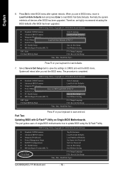
...Quit F8: Q-Flash Top Performance Load Fail-Safe Defaults Load Optimized Defaults Set Supervisor Password Set User Password Save & Exit Setup Exit Without Saving F3: Change Language F10: Save & Exit Setup Time, Date, Hard Disk Type... Part Two: Updating BIOS with Q-FlashTM Utility on your keyboard to save the settings to enter BIOS menu after BIOS has been upgraded. The procedure is completed. CMOS Setup Utility-Copyright (C) 1984-2004 Award Software Standard CMOS Features Advanced BIOS Features Integrated Peripherals Power Management Setup PnP/PCI Configurations PC Health Status...
...Quit F8: Q-Flash Top Performance Load Fail-Safe Defaults Load Optimized Defaults Set Supervisor Password Set User Password Save & Exit Setup Exit Without Saving F3: Change Language F10: Save & Exit Setup Time, Date, Hard Disk Type... Part Two: Updating BIOS with Q-FlashTM Utility on your keyboard to save the settings to enter BIOS menu after BIOS has been upgraded. The procedure is completed. CMOS Setup Utility-Copyright (C) 1984-2004 Award Software Standard CMOS Features Advanced BIOS Features Integrated Peripherals Power Management Setup PnP/PCI Configurations PC Health Status...
Manual
Page 62
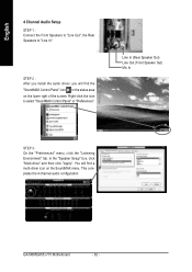
...-driver icon on the lower right of the screen. GA-8I865GM(F)-775 Motherboard - 62 - Line In (Rear Speaker Out) Line Out (Front Speaker Out) Mic In STEP 3: On the "Preferences" menu, click the "Listening Environment" tab. In the "Speaker Setup" box, click "Multi-drive" and then click "Apply". English 4 Channel Audio Setup STEP 1 : Connect the Front Speakers to "Line Out", the Rear Speakers to select "SoundMAX Control Panel" or...
...-driver icon on the lower right of the screen. GA-8I865GM(F)-775 Motherboard - 62 - Line In (Rear Speaker Out) Line Out (Front Speaker Out) Mic In STEP 3: On the "Preferences" menu, click the "Listening Environment" tab. In the "Speaker Setup" box, click "Multi-drive" and then click "Apply". English 4 Channel Audio Setup STEP 1 : Connect the Front Speakers to "Line Out", the Rear Speakers to select "SoundMAX Control Panel" or...

Manual
Page 63
... screen. English 5.1 Channel Audio Setup STEP 1 : Connect the Front Speakers to "Line Out", the Surround Speakers to "Line In", and the Center/ Subwoofer Speakers to select "SoundMAX Control Panel" or "Preferences". Line In (Surround Speaker Out) Line Out (Front Speaker Out) Mic In (Center/Subwoofer Speaker Out) STEP 3: On the "Preferences" menu, click the "Listening Environment" tab. Sound Effect Configuration: At the "Acoustic Environments" menu, users can adjust sound option settings...
... screen. English 5.1 Channel Audio Setup STEP 1 : Connect the Front Speakers to "Line Out", the Surround Speakers to "Line In", and the Center/ Subwoofer Speakers to select "SoundMAX Control Panel" or "Preferences". Line In (Surround Speaker Out) Line Out (Front Speaker Out) Mic In (Center/Subwoofer Speaker Out) STEP 3: On the "Preferences" menu, click the "Listening Environment" tab. Sound Effect Configuration: At the "Acoustic Environments" menu, users can adjust sound option settings...

Manual
Page 65
... listed functions in EasyTune 4? Question 4: Why do I connect the boot HDD to enter BIOS and load Fail-Safe Defaults. 7. Press Del to IDE3 or IDE4 ? However, if the system instability still remains, please clear CMOS to a floppy disk before installing drivers. Appendix Question 3: Why cannot I clear CMOS? Disconnect the power cord from MB. 3. Save changes and reboot the system. If not, please change any setting manually to the steps below: Steps: 1. English 4-2 Troubleshooting...
... listed functions in EasyTune 4? Question 4: Why do I connect the boot HDD to enter BIOS and load Fail-Safe Defaults. 7. Press Del to IDE3 or IDE4 ? However, if the system instability still remains, please clear CMOS to a floppy disk before installing drivers. Appendix Question 3: Why cannot I clear CMOS? Disconnect the power cord from MB. 3. Save changes and reboot the system. If not, please change any setting manually to the steps below: Steps: 1. English 4-2 Troubleshooting...

Manual
Page 66
... item named RAID controller function. gate A20 failure 7 beeps Processor exception interrupt error 8 beeps Display memory read/write failure 9 beeps ROM checksum error 10 beeps CMOS shutdown register read/write error 11 beeps Cache memory bad AWARD BIOS Beep Codes 1 short: System boots successfully 2 short: CMOS setting error 1 long 1 short: DRAM or M/B error 1 long 2 short: Monitor or display card error 1 long 3 short: Keyboard error 1 long 9 short: BIOS ROM error Continuous long beeps: DRAM error Continuous short beeps: Power error Question 11:For the M/B which have connected any of...
... item named RAID controller function. gate A20 failure 7 beeps Processor exception interrupt error 8 beeps Display memory read/write failure 9 beeps ROM checksum error 10 beeps CMOS shutdown register read/write error 11 beeps Cache memory bad AWARD BIOS Beep Codes 1 short: System boots successfully 2 short: CMOS setting error 1 long 1 short: DRAM or M/B error 1 long 2 short: Monitor or display card error 1 long 3 short: Keyboard error 1 long 9 short: BIOS ROM error Continuous long beeps: DRAM error Continuous short beeps: Power error Question 11:For the M/B which have connected any of...


