Manual
Page 4
Table of Contents Box Contents...6 Optional Items...6 GA-890XA-UD3 Motherboard Layout 7 GA-890XA-UD3 Motherboard Block Diagram 8 Chapter 1 Hardware Installation 9 1-1 Installation Precautions 9 1-2 Product Specifications 10 1-3 Installing the CPU and CPU Cooler 13 1-3-1 Installing the CPU 13 1-3-2 Installing the CPU Cooler 15 1-4 Installing the Memory 16 1-4-1 Dual Channel Memory Configuration 16 1-4-2 Installing a Memory 17 1-5 Installing an Expansion Card 18 1-6 Setup...
Table of Contents Box Contents...6 Optional Items...6 GA-890XA-UD3 Motherboard Layout 7 GA-890XA-UD3 Motherboard Block Diagram 8 Chapter 1 Hardware Installation 9 1-1 Installation Precautions 9 1-2 Product Specifications 10 1-3 Installing the CPU and CPU Cooler 13 1-3-1 Installing the CPU 13 1-3-2 Installing the CPU Cooler 15 1-4 Installing the Memory 16 1-4-1 Dual Channel Memory Configuration 16 1-4-2 Installing a Memory 17 1-5 Installing an Expansion Card 18 1-6 Setup...
Manual
Page 8
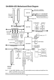
GA-890XA-UD3 Motherboard Block Diagram 1 PCIe x 16 2 PCIe x 8 CPU CLK+/- (200 MHz) PCIe CLK (100 MHz) or AM3 CPU DDR3 1866(O.C.)(Note 1)/1333/1066 MHz Dual Channel Memory Hyper Transport 3.0 Switch 2 eSATA 3Gb/s 2 USB 3.0 PCI Express Bus PCI Express Bus PCIe CLK (100 MHz) x1 x1 x1 RTL8111D RJ45 3 PCI... Express x1 LAN ATA-133/100/66/33 IDE Channel 2 SATA 3Gb/s GIGABYTE SATA2 PCI Express Bus PCI Bus ...
GA-890XA-UD3 Motherboard Block Diagram 1 PCIe x 16 2 PCIe x 8 CPU CLK+/- (200 MHz) PCIe CLK (100 MHz) or AM3 CPU DDR3 1866(O.C.)(Note 1)/1333/1066 MHz Dual Channel Memory Hyper Transport 3.0 Switch 2 eSATA 3Gb/s 2 USB 3.0 PCI Express Bus PCI Express Bus PCIe CLK (100 MHz) x1 x1 x1 RTL8111D RJ45 3 PCI... Express x1 LAN ATA-133/100/66/33 IDE Channel 2 SATA 3Gb/s GIGABYTE SATA2 PCI Express Bus PCI Bus ...
Manual
Page 9
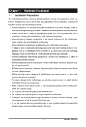
... the power supply has been turned off. • Before turning on the computer power during the installation process can become damaged as a motherboard, CPU or memory.
... the power supply has been turned off. • Before turning on the computer power during the installation process can become damaged as a motherboard, CPU or memory.
Manual
Page 10
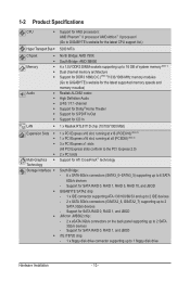
...: AMD Phenom™ II processor/ AMD Athlon™ II processor/ (Go to GIGABYTE's website for the latest CPU support list.) Hyper Transport Bus 5200 MT/s Chipset Memory Audio North...DIMM sockets supporting up to 16 GB of system memory (Note 1) Dual channel memory architecture Support for DDR3 1866(O.C.)(Note 2)/1333/1066 MHz memory modules (Go to GIGABYTE's website for the latest supported memory speeds and momery moudles) Realtek ALC892 codec High ...
...: AMD Phenom™ II processor/ AMD Athlon™ II processor/ (Go to GIGABYTE's website for the latest CPU support list.) Hyper Transport Bus 5200 MT/s Chipset Memory Audio North...DIMM sockets supporting up to 16 GB of system memory (Note 1) Dual channel memory architecture Support for DDR3 1866(O.C.)(Note 2)/1333/1066 MHz memory modules (Go to GIGABYTE's website for the latest supported memory speeds and momery moudles) Realtek ALC892 codec High ...
Manual
Page 12
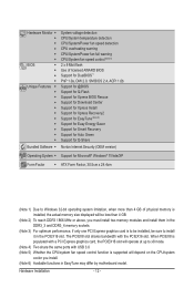
... Factor w ATX Form Factor; 30.5cm x 24.4cm (Note 1) Due to Windows 32-bit operating system limitation, when more than 4 GB of physical memory is installed, the actual memory size displayed will be sure to be installed, be less than 4 GB. (Note 2) To reach DDR3 1866 MHz or above, you must install... two memory modules and install them in the DDR3_3 and DDR3_4 memory sockets. (Note 3) For optimum performance, if only one PCI Express graphics card is supported will operate at up to x8 mode...
... Factor w ATX Form Factor; 30.5cm x 24.4cm (Note 1) Due to Windows 32-bit operating system limitation, when more than 4 GB of physical memory is installed, the actual memory size displayed will be sure to be installed, be less than 4 GB. (Note 2) To reach DDR3 1866 MHz or above, you must install... two memory modules and install them in the DDR3_3 and DDR3_4 memory sockets. (Note 3) For optimum performance, if only one PCI Express graphics card is supported will operate at up to x8 mode...
Manual
Page 13
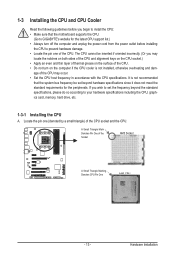
...and thin layer of thermal grease on the computer if the CPU cooler is not recommended that the motherboard supports the CPU. (Go to GIGABYTE's website for the latest CPU support list.) • Always turn on the surface of the CPU socket and the CPU. 1-3 Installing ...the CPU and CPU Cooler Read the following guidelines before installing the CPU to your hardware specifications including the CPU, graphics card, memory, hard drive, etc. 1-3-1 Installing the CPU A. It is not installed, otherwise overheating and dam- Hardware Installation age of the Socket AM3 Socket...
...and thin layer of thermal grease on the computer if the CPU cooler is not recommended that the motherboard supports the CPU. (Go to GIGABYTE's website for the latest CPU support list.) • Always turn on the surface of the CPU socket and the CPU. 1-3 Installing ...the CPU and CPU Cooler Read the following guidelines before installing the CPU to your hardware specifications including the CPU, graphics card, memory, hard drive, etc. 1-3-1 Installing the CPU A. It is not installed, otherwise overheating and dam- Hardware Installation age of the Socket AM3 Socket...
Manual
Page 16
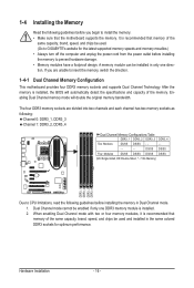
... be enabled if only one direction. Dual Channel mode cannot be used . (Go to GIGABYTE's website for optimum performance. If you begin to insert the memory, switch the direction. 1-4-1 Dual Channel Memory Configuration This motherboard provides four DDR3 memory sockets and supports Dual Channel Technology. When enabling Dual Channel mode with two or four...
... be enabled if only one direction. Dual Channel mode cannot be used . (Go to GIGABYTE's website for optimum performance. If you begin to insert the memory, switch the direction. 1-4-1 Dual Channel Memory Configuration This motherboard provides four DDR3 memory sockets and supports Dual Channel Technology. When enabling Dual Channel mode with two or four...
Manual
Page 17
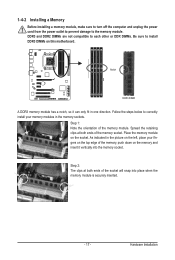
...clips at both ends of the memory socket. Notch DDR3 DIMM A DDR3 memory module has a notch, so it vertically into place when the memory module is securely inserted. - 17 - Spread the retaining clips at both ends of the socket will snap into the memory socket. DDR3 and DDR2 DIMMs ...socket. Step 1: Note the orientation of the memory, push down on the memory and insert it can only fit in the memory sockets. As indicated in the picture on the left, place your memory modules in one direction. 1-4-2 Installing a Memory Before installing a memory module, make sure to turn off the ...
...clips at both ends of the memory socket. Notch DDR3 DIMM A DDR3 memory module has a notch, so it vertically into place when the memory module is securely inserted. - 17 - Spread the retaining clips at both ends of the socket will snap into the memory socket. DDR3 and DDR2 DIMMs ...socket. Step 1: Note the orientation of the memory, push down on the memory and insert it can only fit in the memory sockets. As indicated in the picture on the left, place your memory modules in one direction. 1-4-2 Installing a Memory Before installing a memory module, make sure to turn off the ...
Manual
Page 36
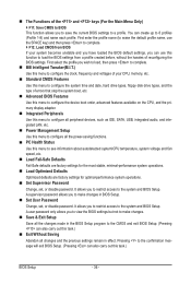
..., you wish to load, then press to complete. MB Intelligent Tweaker(M.I.T.) Use this menu to configure the clock, frequency and voltages of your CPU, memory, etc. Standard CMOS Features Use this menu to configure all peripheral devices, such as IDE, SATA, USB, integrated audio, and integrated LAN, etc. ...
..., you wish to load, then press to complete. MB Intelligent Tweaker(M.I.T.) Use this menu to configure the clock, frequency and voltages of your CPU, memory, etc. Standard CMOS Features Use this menu to configure all peripheral devices, such as IDE, SATA, USB, integrated audio, and integrated LAN, etc. ...
Manual
Page 37
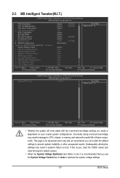
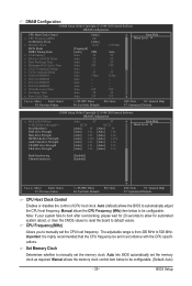
... dependent on your overall system configurations. BIOS Setup CPU Host Clock Control x CPU Frequency(MHz) PCIE Clock(MHz) HT Link Width HT Link Frequency Set Memory Clock x Memory Clock } DRAM Configuration ******** System Voltage Optimized ******** System Voltage Control x CPU PLL Voltage Control x DRAM Voltage Control x DDR VTT Voltage Control x NB Voltage Control x ... settings you made is for advanced users only and we recommend you set the System Voltage Control item to Auto to CPU, chipset, or memory and reduce the useful life of these components.
... dependent on your overall system configurations. BIOS Setup CPU Host Clock Control x CPU Frequency(MHz) PCIE Clock(MHz) HT Link Width HT Link Frequency Set Memory Clock x Memory Clock } DRAM Configuration ******** System Voltage Optimized ******** System Voltage Control x CPU PLL Voltage Control x DRAM Voltage Control x DDR VTT Voltage Control x NB Voltage Control x ... settings you made is for advanced users only and we recommend you set the System Voltage Control item to Auto to CPU, chipset, or memory and reduce the useful life of these components.
Manual
Page 38
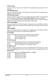
... seconds to allow for automated system reboot, or clear the CMOS values to reset the board to X5.33. X8.00 Sets Memory Clock to manually set the memory clock. CPU NorthBridge Freq. Auto sets the PCIe clock frequency to standard 100 MHz. (Default: Auto) HT Link Width Allows ...you to X8.00. Set Memory Clock Determines whether to 150 MHz. BIOS Setup - 38 - The adjustable range is highly recommended that the CPU frequency be configurable. Auto BIOS will...
... seconds to allow for automated system reboot, or clear the CMOS values to reset the board to X5.33. X8.00 Sets Memory Clock to manually set the memory clock. CPU NorthBridge Freq. Auto sets the PCIe clock frequency to standard 100 MHz. (Default: Auto) HT Link Width Allows ...you to X8.00. Set Memory Clock Determines whether to 150 MHz. BIOS Setup - 38 - The adjustable range is highly recommended that the CPU frequency be configurable. Auto BIOS will...
Manual
Page 39
.... DRAM Configuration CMOS Setup Utility-Copyright (C) 1984-2010 Award Software DRAM Configuration CPU Host Clock Control x CPU Frequency(MHz) Set Memory Clock x Memory Clock DCTs Mode [Unganged] DDR3 Timing Items [Auto] x CAS# latency Auto x RAS to CAS R/W Delay Auto x Row Precharge Time ... recommended that the CPU frequency be configurable. Important It is from 200 MHz to 500 MHz. Set Memory Clock Determines whether to be set the memory clock as required. Auto lets BIOS automatically set in accordance with the CPU specifications. Manual allows the...
.... DRAM Configuration CMOS Setup Utility-Copyright (C) 1984-2010 Award Software DRAM Configuration CPU Host Clock Control x CPU Frequency(MHz) Set Memory Clock x Memory Clock DCTs Mode [Unganged] DDR3 Timing Items [Auto] x CAS# latency Auto x RAS to CAS R/W Delay Auto x Row Precharge Time ... recommended that the CPU frequency be configurable. Important It is from 200 MHz to 500 MHz. Set Memory Clock Determines whether to be set the memory clock as required. Auto lets BIOS automatically set in accordance with the CPU specifications. Manual allows the...

Manual
Page 40
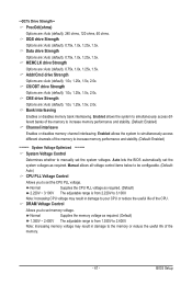
...default), 1T, 2T. Trfc0 for DIMM2 Options are : Auto (default), 4T~7T. Write Recovery Time Options are : Auto (default), 11T~42T. Unganged Sets memory control mode to two single-channel. (Default) DDR3 Timing Items Manual allows all DDR3 Timing items below to X8.00. Row Cycle Time Options are... : Auto (default), 5T~8T, 10T, 12T. Ganged Sets memory control mode to X4.00. TwTr Command Delay Options are : Auto (default), 90ns, 110ns, 160ns, 300ns, 350ns. Trfc2 for DIMM1 Options are : ...
...default), 1T, 2T. Trfc0 for DIMM2 Options are : Auto (default), 4T~7T. Write Recovery Time Options are : Auto (default), 11T~42T. Unganged Sets memory control mode to two single-channel. (Default) DDR3 Timing Items Manual allows all DDR3 Timing items below to X8.00. Row Cycle Time Options are... : Auto (default), 5T~8T, 10T, 12T. Ganged Sets memory control mode to X4.00. TwTr Command Delay Options are : Auto (default), 90ns, 110ns, 160ns, 300ns, 350ns. Trfc2 for DIMM1 Options are : ...
Manual
Page 41
... 3.100V. Enabled allows the system to set the system voltages. DRAM Voltage Control Allows you to simultaneously access different banks of the memory. - 41 - MEMCLK drive Strength Options are : Auto (default), 1.0x, 1.25x, 1.5x, 2.0x. CKE drive Strength Options are : ...Auto (default), 0.75x, 1.0x, 1.25x, 1.5x. Bank Interleaving Enables or disables memory bank interleaving. Addr/Cmd drive Strength Options are : Auto (default), 0.75x, 1.0x, 1.25x, 1.5x. Data drive Strength Options are : Auto (default), 1.0x...
... 3.100V. Enabled allows the system to set the system voltages. DRAM Voltage Control Allows you to simultaneously access different banks of the memory. - 41 - MEMCLK drive Strength Options are : Auto (default), 1.0x, 1.25x, 1.5x, 2.0x. CKE drive Strength Options are : ...Auto (default), 0.75x, 1.0x, 1.25x, 1.5x. Bank Interleaving Enables or disables memory bank interleaving. Addr/Cmd drive Strength Options are : Auto (default), 0.75x, 1.0x, 1.25x, 1.5x. Data drive Strength Options are : Auto (default), 1.0x...
Manual
Page 42
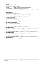
...Setup - 42 - Normal Supplies the North Bridge voltage as required. (Default) 0.720V ~ 1.050V The adjustable range is from 0.720V to set the memory VTT voltage. Normal Supplies the North Bridge PCIe PLL voltage as required. (Default) 1.000V ~ 1.500V The adjustable range is dependent on the CPU ...being installed. (Default: Normal) Note: Increasing CPU voltage may result in damage to the memory or reduce the useful life of the CPU. NB Voltage Control Allows you to 2.100V. The adjustable range is from 1.450V to set the...
...Setup - 42 - Normal Supplies the North Bridge voltage as required. (Default) 0.720V ~ 1.050V The adjustable range is from 0.720V to set the memory VTT voltage. Normal Supplies the North Bridge PCIe PLL voltage as required. (Default) 1.000V ~ 1.500V The adjustable range is dependent on the CPU ...being installed. (Default: Normal) Note: Increasing CPU voltage may result in damage to the memory or reduce the useful life of the CPU. NB Voltage Control Allows you to 2.100V. The adjustable range is from 1.450V to set the...
Manual
Page 43
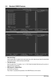
...: Fail-Safe Defaults ESC: Exit F1: General Help F7: Optimized Defaults CMOS Setup Utility-Copyright (C) 1984-2010 Award Software Standard CMOS Features Halt On Base Memory Extended Memory [All, But Keyboard] 640K 1022M Item Help Menu Level Move Enter: Select F5: Previous Values +/-/PU/PD: Value F10: Save F6: Fail-Safe...
...: Fail-Safe Defaults ESC: Exit F1: General Help F7: Optimized Defaults CMOS Setup Utility-Copyright (C) 1984-2010 Award Software Standard CMOS Features Halt On Base Memory Extended Memory [All, But Keyboard] 640K 1022M Item Help Menu Level Move Enter: Select F5: Previous Values +/-/PU/PD: Value F10: Save F6: Fail-Safe...
Manual
Page 44
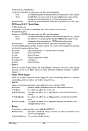
... this item to None so the system will skip the detection of the device during the POST for faster system startup. Sector Number of extended memory. Floppy 3 Mode Support Allows you do not install a floppy disk drive, set this item to None. All Errors Whenever the BIOS detects.... All, But Disk/Key The system boot will not stop for a keyboard or a floppy disk drive error but it will stop . Extended Memory The amount of sectors. Access Mode Sets the hard drive access mode. The following fields display your system. Cylinder Number of heads. Head Number ...
... this item to None so the system will skip the detection of the device during the POST for faster system startup. Sector Number of extended memory. Floppy 3 Mode Support Allows you do not install a floppy disk drive, set this item to None. All Errors Whenever the BIOS detects.... All, But Disk/Key The system boot will not stop for a keyboard or a floppy disk drive error but it will stop . Extended Memory The amount of sectors. Access Mode Sets the hard drive access mode. The following fields display your system. Cylinder Number of heads. Head Number ...
Manual
Page 51
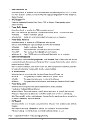
Keyboard 98 Press POWER button on the Windows 98 keyboard to turn on the system. Memory The system returns to its last known awake state upon the return of Month): Turn on the system at least 1A on the +5VSB lead. (...
Keyboard 98 Press POWER button on the Windows 98 keyboard to turn on the system. Memory The system returns to its last known awake state upon the return of Month): Turn on the system at least 1A on the +5VSB lead. (...
Manual
Page 61
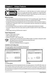
... Xpress Recovery2 are attached to the first IDE and the first SATA connectors, the hard drive on your system data and perform restoration of system memory • VESA compatible graphics card • Windows XP with Xpress Recovery cannot be restored using Xpress Recovery2. • USB hard drives are not supported. •...
... Xpress Recovery2 are attached to the first IDE and the first SATA connectors, the hard drive on your system data and perform restoration of system memory • VESA compatible graphics card • Windows XP with Xpress Recovery cannot be restored using Xpress Recovery2. • USB hard drives are not supported. •...
Manual
Page 68
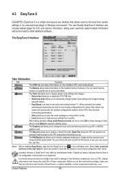
...Easy mode/Advanced mode, be changed linearly based on a specific slot to see its information. You can select memory module on the CPU temperature thresholds you to change system clock settings and voltages settings using the sliders. •...Tabs Information Tab Function The CPU tab provides information on the installed memory module(s). Unique Features - 68 - After restart, the system will operate with the optimum overclocking configuration after restart. 4-3 EasyTune 6 GIGABYTE's EasyTune 6 is a simple and easy-to-use interface that...
...Easy mode/Advanced mode, be changed linearly based on a specific slot to see its information. You can select memory module on the CPU temperature thresholds you to change system clock settings and voltages settings using the sliders. •...Tabs Information Tab Function The CPU tab provides information on the installed memory module(s). Unique Features - 68 - After restart, the system will operate with the optimum overclocking configuration after restart. 4-3 EasyTune 6 GIGABYTE's EasyTune 6 is a simple and easy-to-use interface that...


