
Manual
Page 4
... Box Contents...6 Optional Items...6 GA-880GM-D2H Motherboard Layout 7 GA-880GM-D2H Motherboard Block Diagram 8 Chapter 1 Hardware Installation 9 1-1 Installation Precautions 9 1-2 Product Specifications 10 1-3 Installing the CPU and CPU Cooler 13 1-3-1 Installing the CPU 13 1-3-2 Installing the CPU Cooler 15 1-4 Installing the Memory 16 1-4-1 Dual Channel Memory Configuration 16 1-4-2 Installing a Memory 17 1-5 Installing an Expansion Card 18 1-6 Back Panel Connectors 19 1-7 Internal Connectors 21 Chapter 2 BIOS Setup 31 2-1 Startup Screen 32 2-2 The Main Menu 33 2-3 MB...
... Box Contents...6 Optional Items...6 GA-880GM-D2H Motherboard Layout 7 GA-880GM-D2H Motherboard Block Diagram 8 Chapter 1 Hardware Installation 9 1-1 Installation Precautions 9 1-2 Product Specifications 10 1-3 Installing the CPU and CPU Cooler 13 1-3-1 Installing the CPU 13 1-3-2 Installing the CPU Cooler 15 1-4 Installing the Memory 16 1-4-1 Dual Channel Memory Configuration 16 1-4-2 Installing a Memory 17 1-5 Installing an Expansion Card 18 1-6 Back Panel Connectors 19 1-7 Internal Connectors 21 Chapter 2 BIOS Setup 31 2-1 Startup Screen 32 2-2 The Main Menu 33 2-3 MB...
Manual
Page 5
... Updating the BIOS with the Q-Flash Utility 64 4-2-2 Updating the BIOS with the @BIOS Utility 67 4-3 EasyTune 6...68 4-4 Q-Share...69 4-5 SMART Recovery 70 4-6 Auto Green...71 Chapter 5 Appendix...73 5-1 Configuring SATA Hard Drive(s 73 5-1-1 Configuring the Onboard SATA Controller 73 5-1-2 Making a SATA RAID/AHCI Driver Diskette 79 5-1-3 Installing the SATA RAID/AHCI Driver and Operating System 81 5-2 Configuring Audio Input and Output 85 5-2-1 Configuring 2/4/5.1/7.1-Channel Audio 85 5-2-2 Configuring S/PDIF In/Out 88 5-2-3 Configuring Microphone Recording 90 5-2-4 Using the Sound...
... Updating the BIOS with the Q-Flash Utility 64 4-2-2 Updating the BIOS with the @BIOS Utility 67 4-3 EasyTune 6...68 4-4 Q-Share...69 4-5 SMART Recovery 70 4-6 Auto Green...71 Chapter 5 Appendix...73 5-1 Configuring SATA Hard Drive(s 73 5-1-1 Configuring the Onboard SATA Controller 73 5-1-2 Making a SATA RAID/AHCI Driver Diskette 79 5-1-3 Installing the SATA RAID/AHCI Driver and Operating System 81 5-2 Configuring Audio Input and Output 85 5-2-1 Configuring 2/4/5.1/7.1-Channel Audio 85 5-2-2 Configuring S/PDIF In/Out 88 5-2-3 Configuring Microphone Recording 90 5-2-4 Using the Sound...

Manual
Page 8
GA-880GM-D2H Motherboard Block Diagram PCIe CLK (100 MHz) AM3 CPU CPU CLK+/- (200 MHz) DDR3 1666(O.C.)/1333/1066 MHz Dual Channel Memory 1 PCI Express x16 Hyper Transport Bus PCI Express x16 PCI Express Bus x1 PCIe CLK (100 MHz) 1 PCI Express x1 Realtek RTL8111D/E RJ45 LAN AMD 880G GFX CLK (100 MHz) D-Sub DVI-D (Note) HDMI(Note) 12 USB Ports PCI Bus AMD SB710 ATA-133/100/66/33 IDE Channel 4 SATA 3Gb/s CODEC LPC Bus iTE IT8718 Dual BIOS Floppy COM Port MIC Line Out Line...
GA-880GM-D2H Motherboard Block Diagram PCIe CLK (100 MHz) AM3 CPU CPU CLK+/- (200 MHz) DDR3 1666(O.C.)/1333/1066 MHz Dual Channel Memory 1 PCI Express x16 Hyper Transport Bus PCI Express x16 PCI Express Bus x1 PCIe CLK (100 MHz) 1 PCI Express x1 Realtek RTL8111D/E RJ45 LAN AMD 880G GFX CLK (100 MHz) D-Sub DVI-D (Note) HDMI(Note) 12 USB Ports PCI Bus AMD SB710 ATA-133/100/66/33 IDE Channel 4 SATA 3Gb/s CODEC LPC Bus iTE IT8718 Dual BIOS Floppy COM Port MIC Line Out Line...

Manual
Page 10
...x PCI slots Storage Interface South Bridge: - 1 x IDE connector supporting ATA-133/100/66/33 and up to 2 IDE devices - 4 x SATA 3Gb/s connectors supporting up to 1 floppy disk drive USB South Bridge: - 1-2 Product Specifications CPU Support for AM3 processors: AMD Phenom™ II processor/ AMD Athlon™ II processor (Go to GIGABYTE's website for the latest CPU support list.) Hyper Transport Bus 5200 MT/s Chipset Memory Onboard Graphics Audio...
...x PCI slots Storage Interface South Bridge: - 1 x IDE connector supporting ATA-133/100/66/33 and up to 2 IDE devices - 4 x SATA 3Gb/s connectors supporting up to 1 floppy disk drive USB South Bridge: - 1-2 Product Specifications CPU Support for AM3 processors: AMD Phenom™ II processor/ AMD Athlon™ II processor (Go to GIGABYTE's website for the latest CPU support list.) Hyper Transport Bus 5200 MT/s Chipset Memory Onboard Graphics Audio...

Manual
Page 12
... of the onboard digital graphics ports (HDMI and DVI-D) for output when in the BIOS Setup program or when during the POST screens. (Note 4) To configure 7.1-channel audio, you have to use an HD front panel audio module and enable themulti-channel audio feature through the audio driver. (Note 5) Whether the CPU fan speed control function is supported will depend on the CPU cooler you install. (Note 6) Available functions in EasyTune may differ by motherboard model. Hardware Installation - 12...
... of the onboard digital graphics ports (HDMI and DVI-D) for output when in the BIOS Setup program or when during the POST screens. (Note 4) To configure 7.1-channel audio, you have to use an HD front panel audio module and enable themulti-channel audio feature through the audio driver. (Note 5) Whether the CPU fan speed control function is supported will depend on the CPU cooler you install. (Note 6) Available functions in EasyTune may differ by motherboard model. Hardware Installation - 12...
Manual
Page 18
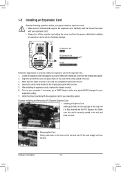
... to BIOS Setup to the chassis back panel with the expansion card in the slot. 3. Locate an expansion slot that came with the slot, and press down on the card are completely inserted into the PCI Express slot. Remove the metal slot cover from the power outlet before you begin to install an expansion card: • Make sure the motherboard supports the expansion card. After installing all expansion cards, replace the chassis cover(s). 6. Hardware Installation - 18 - 1-5 Installing...
... to BIOS Setup to the chassis back panel with the expansion card in the slot. 3. Locate an expansion slot that came with the slot, and press down on the card are completely inserted into the PCI Express slot. Remove the metal slot cover from the power outlet before you begin to install an expansion card: • Make sure the motherboard supports the expansion card. After installing all expansion cards, replace the chassis cover(s). 6. Hardware Installation - 18 - 1-5 Installing...

Manual
Page 20
... short inside the cable connector. The table below . • CPU: AMD Phenom™ X3 processor or above • Memory: Two 1 GB DDR3 1066 MHz memory modules with dual channel mode enabled • BIOS Setup: At least 256 MB of the LAN port LEDs. Use this jack. This jack can be connected to connect front speakers in Chapter 5, "Configuring 2/4/5.1/7.1-Channel Audio." • When removing the cable connected to the recom mended system requirements (or better) below shows the supported dual display configurations. Connection/ Speed LED...
... short inside the cable connector. The table below . • CPU: AMD Phenom™ X3 processor or above • Memory: Two 1 GB DDR3 1066 MHz memory modules with dual channel mode enabled • BIOS Setup: At least 256 MB of the LAN port LEDs. Use this jack. This jack can be connected to connect front speakers in Chapter 5, "Configuring 2/4/5.1/7.1-Channel Audio." • When removing the cable connected to the recom mended system requirements (or better) below shows the supported dual display configurations. Connection/ Speed LED...

Manual
Page 28
... short the two pins or use a metal object like a screwdriver to touch the two pins for BIOS configurations). date information and BIOS configurations) and reset the CMOS values to Chapter 2, "BIOS Setup," for a few seconds. Failure to do so may cause damage to the motherboard. • After system restart, go to BIOS Setup to load factory defaults (select Load Optimized Defaults) or manually configure the BIOS settings (refer to factory defaults. Hardware Installation - 28 - Pin No. To clear...
... short the two pins or use a metal object like a screwdriver to touch the two pins for BIOS configurations). date information and BIOS configurations) and reset the CMOS values to Chapter 2, "BIOS Setup," for a few seconds. Failure to do so may cause damage to the motherboard. • After system restart, go to BIOS Setup to load factory defaults (select Load Optimized Defaults) or manually configure the BIOS settings (refer to factory defaults. Hardware Installation - 28 - Pin No. To clear...
Manual
Page 34
... CPU, memory, etc. Standard CMOS Features Use this menu to configure the system time and date, hard drive types, floppy disk drive types, and the type of errors that stop the system boot, etc. Advanced BIOS Features Use this menu to configure the device boot order, advanced features available on the CPU, and the primary display adapter. Integrated Peripherals Use this menu to configure all peripheral devices, such as IDE, SATA, USB, integrated audio, and integrated LAN, etc. Power Management Setup Use...
... CPU, memory, etc. Standard CMOS Features Use this menu to configure the system time and date, hard drive types, floppy disk drive types, and the type of errors that stop the system boot, etc. Advanced BIOS Features Use this menu to configure the device boot order, advanced features available on the CPU, and the primary display adapter. Integrated Peripherals Use this menu to configure all peripheral devices, such as IDE, SATA, USB, integrated audio, and integrated LAN, etc. Power Management Setup Use...
Manual
Page 37
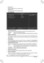
...This option is configurable only if Init Display First under Advanced BIOS Features is set the VGA Core clock. CPU core 2(Note) Enables or disables CPU Core 2. (Default: Enabled) CPU core 3 (Note) Enables or disables CPU Core 3. (Default: Enabled) IGX Configuration CMOS Setup Utility-Copyright (C) 1984-2010 Award Software IGX Configuration Internal Graphics Mode UMA Frame Buffer Size x Surround View Onboard VGA output connect VGA Core Clock control x VGA Core Clock(MHz) [UMA] [Auto] Disabled [D-SUB/DVI] [Disabled] 350 Item Help Menu Level Move Enter...
...This option is configurable only if Init Display First under Advanced BIOS Features is set the VGA Core clock. CPU core 2(Note) Enables or disables CPU Core 2. (Default: Enabled) CPU core 3 (Note) Enables or disables CPU Core 3. (Default: Enabled) IGX Configuration CMOS Setup Utility-Copyright (C) 1984-2010 Award Software IGX Configuration Internal Graphics Mode UMA Frame Buffer Size x Surround View Onboard VGA output connect VGA Core Clock control x VGA Core Clock(MHz) [UMA] [Auto] Disabled [D-SUB/DVI] [Disabled] 350 Item Help Menu Level Move Enter...
Manual
Page 38
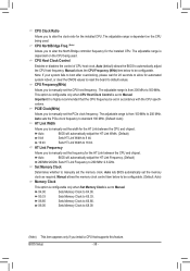
... used . Auto (default) allows the BIOS to X5.33. Note: If your system fails to boot after overclocking, please wait for 20 seconds to allow for the installed CPU. Important It is set the memory clock as required. Auto lets BIOS automatically set to Manual. X5.33 Sets Memory Clock to automatically adjust the CPU host frequency. X6.66 Sets Memory Clock to 200 MHz. This option is configurable only when CPU Host Clock Control is highly recommended that supports...
... used . Auto (default) allows the BIOS to X5.33. Note: If your system fails to boot after overclocking, please wait for 20 seconds to allow for the installed CPU. Important It is set the memory clock as required. Auto lets BIOS automatically set to Manual. X5.33 Sets Memory Clock to automatically adjust the CPU host frequency. X6.66 Sets Memory Clock to 200 MHz. This option is configurable only when CPU Host Clock Control is highly recommended that supports...
Manual
Page 40
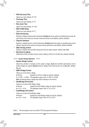
...-stating Determines whether to enable memory clock tri-stating in damage to increase memory performance and stability. (Default: Enabled) Channel interleave Enables or disables memory channel interleaving. Manual allows all voltage control items below to be configurable. (Default: Manual) DDR3 Voltage Control Allows you to set the South Bridge voltage. SouthBridge Volt Control Allows you to set memory voltage. NorthBridge Volt Control Allows you install a CPU that supports this feature. Normal Supplies the North Bridge voltage as required. (Default) +0.1V ~ +0.3V The...
...-stating Determines whether to enable memory clock tri-stating in damage to increase memory performance and stability. (Default: Enabled) Channel interleave Enables or disables memory channel interleaving. Manual allows all voltage control items below to be configurable. (Default: Manual) DDR3 Voltage Control Allows you to set the South Bridge voltage. SouthBridge Volt Control Allows you to set memory voltage. NorthBridge Volt Control Allows you install a CPU that supports this feature. Normal Supplies the North Bridge voltage as required. (Default) +0.1V ~ +0.3V The...
Manual
Page 44
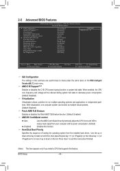
2-5 Advanced BIOS Features CMOS Setup Utility-Copyright (C) 1984-2010 Award Software Advanced BIOS Features } IGX Configuration AMD C1E Support (Note) Virtualization Patch AMD TLB Erratum AMD K8 Cool&Quiet control } Hard Disk Boot Priority First Boot Device Second Boot Device Third Boot Device Password Check HDD S.M.A.R.T. Capability Away Mode Backup BIOS Image to HDD Init Display First [Press Enter] [Disabled] [Disabled] [Enabled] [Auto] [Press Enter] [Floppy] [Hard Disk] [CDROM] [Setup] [Disabled] [Disabled] [Disabled] [PCI Slot] Item Help Menu Level ...
2-5 Advanced BIOS Features CMOS Setup Utility-Copyright (C) 1984-2010 Award Software Advanced BIOS Features } IGX Configuration AMD C1E Support (Note) Virtualization Patch AMD TLB Erratum AMD K8 Cool&Quiet control } Hard Disk Boot Priority First Boot Device Second Boot Device Third Boot Device Password Check HDD S.M.A.R.T. Capability Away Mode Backup BIOS Image to HDD Init Display First [Press Enter] [Disabled] [Disabled] [Enabled] [Auto] [Press Enter] [Floppy] [Hard Disk] [CDROM] [Setup] [Disabled] [Disabled] [Disabled] [PCI Slot] Item Help Menu Level ...

Manual
Page 45
... Boot Device Specifies the boot order from the installed PCI graphics card, PCI Express graphics card, or the onboard graphics. Use the up or down arrow key to select a device and press to the hard drive. HDD S.M.A.R.T. PEG1 Sets the PCI Express graphics card on the PCIEX16_1 slot as the first display. Capability Enables or disables the S.M.A.R.T. (Self Monitoring and Reporting Technology) capability of your system to report read/write errors of the monitor display from the available devices. If the system BIOS is installed. (Default: Enabled) Away Mode Enables...
... Boot Device Specifies the boot order from the installed PCI graphics card, PCI Express graphics card, or the onboard graphics. Use the up or down arrow key to select a device and press to the hard drive. HDD S.M.A.R.T. PEG1 Sets the PCI Express graphics card on the PCIEX16_1 slot as the first display. Capability Enables or disables the S.M.A.R.T. (Self Monitoring and Reporting Technology) capability of your system to report read/write errors of the monitor display from the available devices. If the system BIOS is installed. (Default: Enabled) Away Mode Enables...

Manual
Page 49
... state. BIOS Setup The system can be awakened from an ACPI sleep state by a wake-up signal from a PCI or PCIe device. S3(STR) Enables the system to enter the ACPI S3 (Suspend to enter the ACPI S1 (Power on Windows 7/Vista operating system only. - 49 - 2-7 Power Management Setup CMOS Setup Utility-Copyright (C) 1984-2010 Award Software Power Management Setup ACPI Suspend Type Soft-Off by Power button USB Wake Up from a modem that supports wake-up function. (Default: Disabled) PME Event Wake Up Allows...
... state. BIOS Setup The system can be awakened from an ACPI sleep state by a wake-up signal from a PCI or PCIe device. S3(STR) Enables the system to enter the ACPI S3 (Suspend to enter the ACPI S1 (Power on Windows 7/Vista operating system only. - 49 - 2-7 Power Management Setup CMOS Setup Utility-Copyright (C) 1984-2010 Award Software Power Management Setup ACPI Suspend Type Soft-Off by Power button USB Wake Up from a modem that supports wake-up function. (Default: Disabled) PME Event Wake Up Allows...
Manual
Page 64
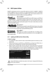
... BIOS file (e.g. 880GD2H.E2) to enter Q-Flash. What is DualBIOS™? Motherboards that matches your floppy disk, USB flash drive, or hard drive. Before You Begin 1. Restart the system. GA-880GM-D2H E2 . . . . : BIOS Setup : XpressRecovery2 : Boot Menu : Qflash 05/18/2010-RS880P-SB710-7A66BG0MC-00 Because BIOS flashing is corrupted or damaged, the backup BIOS will download the latest BIOS file from the hassles of system safety, users cannot update the backup BIOS manually. 4-2 BIOS Update Utilities GIGABYTE motherboards provide two unique BIOS update tools, Q-Flash...
... BIOS file (e.g. 880GD2H.E2) to enter Q-Flash. What is DualBIOS™? Motherboards that matches your floppy disk, USB flash drive, or hard drive. Before You Begin 1. Restart the system. GA-880GM-D2H E2 . . . . : BIOS Setup : XpressRecovery2 : Boot Menu : Qflash 05/18/2010-RS880P-SB710-7A66BG0MC-00 Because BIOS flashing is corrupted or damaged, the backup BIOS will download the latest BIOS file from the hassles of system safety, users cannot update the backup BIOS manually. 4-2 BIOS Update Utilities GIGABYTE motherboards provide two unique BIOS update tools, Q-Flash...
Manual
Page 73
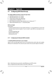
... you use two hard drives with identical model and capacity). Appendix C. Chapter 5 Appendix 5-1 Configuring SATA Hard Drive(s) To configure SATA hard drive(s), follow the steps below: A. Configuring RAID set to available SATA port on the SATA controller. (Note 2) Required when the SATA controller is recommended that you begin Please prepare: • At least two SATA hard drives (to create RAID array on the motherboard. Then connect the power connector from your computer. Install SATA hard drive(s) in BIOS Setup. A. Configure SATA controller mode in your power supply...
... you use two hard drives with identical model and capacity). Appendix C. Chapter 5 Appendix 5-1 Configuring SATA Hard Drive(s) To configure SATA hard drive(s), follow the steps below: A. Configuring RAID set to available SATA port on the SATA controller. (Note 2) Required when the SATA controller is recommended that you begin Please prepare: • At least two SATA hard drives (to create RAID array on the motherboard. Then connect the power connector from your computer. Install SATA hard drive(s) in BIOS Setup. A. Configure SATA controller mode in your power supply...

Manual
Page 79
For installing Windows Vista, you need to install the SATA controller driver during the Windows setup process. Steps: 1: Boot from the motherboard driver disk to be recognized during the OS installation. Press after the command (Figure 1): A:\>copy d:\bootdrv\sbxxx\x86\*.* (Note) Figure 1 (Note) Type the driver directory based on the operating system to a USB flash drive. See the instructions below about how to the following command. In MS-DOS mode: Prepare...
For installing Windows Vista, you need to install the SATA controller driver during the Windows setup process. Steps: 1: Boot from the motherboard driver disk to be recognized during the OS installation. Press after the command (Figure 1): A:\>copy d:\bootdrv\sbxxx\x86\*.* (Note) Figure 1 (Note) Type the driver directory based on the operating system to a USB flash drive. See the instructions below about how to the following command. In MS-DOS mode: Prepare...

Manual
Page 81
... AMD AHCI Compatible RAID Controller-x86 platform and press . Select the SCSI Adapter you can pro- A. Windows Setup Press F6 if you need to the previous screen. The followings are ready to install Windows Vista/ XP onto your system to boot from the following list, or press ESC to return to install a third party SCSI or RAID driver. Installing Windows XP Step 1: Restart your hard drive(s). Figure 1 Step 2: Insert the floppy disk...
... AMD AHCI Compatible RAID Controller-x86 platform and press . Select the SCSI Adapter you can pro- A. Windows Setup Press F6 if you need to the previous screen. The followings are ready to install Windows Vista/ XP onto your system to boot from the following list, or press ESC to return to install a third party SCSI or RAID driver. Installing Windows XP Step 1: Restart your hard drive(s). Figure 1 Step 2: Insert the floppy disk...

Manual
Page 93
... Service Pack 1 or Service Pack 2 has been installed (check in Chapter 1 to short the jumper to clear the CMOS values. Step 2: Check if Audio Device on the CLR_CMOS jumper in My Computer > Properties > Gen- A: The following Award BIOS beep code descriptions may help you identify possible computer problems. (For reference only.) 1 short: System boots successfully 2 short: CMOS setting error 1 long, 3 short: Keyboard error 1 long, 1 short: Memory or motherboard error 1 long, 9 short: BIOS ROM error 1 long, 2 short: Monitor or graphics card error Continuous long beeps: Graphics card...
... Service Pack 1 or Service Pack 2 has been installed (check in Chapter 1 to short the jumper to clear the CMOS values. Step 2: Check if Audio Device on the CLR_CMOS jumper in My Computer > Properties > Gen- A: The following Award BIOS beep code descriptions may help you identify possible computer problems. (For reference only.) 1 short: System boots successfully 2 short: CMOS setting error 1 long, 3 short: Keyboard error 1 long, 1 short: Memory or motherboard error 1 long, 9 short: BIOS ROM error 1 long, 2 short: Monitor or graphics card error Continuous long beeps: Graphics card...


