Manual
Page 1
GA-770T-D3L AM3+ socket motherboard for AMD Phenom™ II processor/ AMD Athlon™ II processor User's Manual Rev. 3101 12ME-770TD3L-3101R
GA-770T-D3L AM3+ socket motherboard for AMD Phenom™ II processor/ AMD Athlon™ II processor User's Manual Rev. 3101 12ME-770TD3L-3101R
Manual
Page 2
Motherboard GA-770T-D3L Jul. 26, 2010 Motherboard GA-770T-D3L Jul 26, 2010
Motherboard GA-770T-D3L Jul. 26, 2010 Motherboard GA-770T-D3L Jul 26, 2010
Manual
Page 3
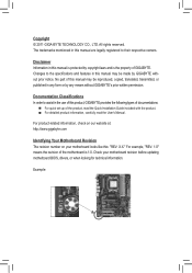
...the Quick Installation Guide included with the product. For detailed product information, carefully read the User's Manual. Check your motherboard looks like this manual may be made by copyright laws and is 1.0. For example, "REV: 1.0" means the revision of...use of this manual is protected by GIGABYTE without GIGABYTE's prior written permission. For product-related information, check on our website at: http://www.gigabyte.com Identifying Your Motherboard Revision The revision number on your motherboard revision before updating motherboard BIOS, drivers, or when looking for...
...the Quick Installation Guide included with the product. For detailed product information, carefully read the User's Manual. Check your motherboard looks like this manual may be made by copyright laws and is 1.0. For example, "REV: 1.0" means the revision of...use of this manual is protected by GIGABYTE without GIGABYTE's prior written permission. For product-related information, check on our website at: http://www.gigabyte.com Identifying Your Motherboard Revision The revision number on your motherboard revision before updating motherboard BIOS, drivers, or when looking for...
Manual
Page 4
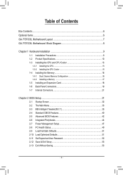
Table of Contents Box Contents...6 Optional Items...6 GA-770T-D3L Motherboard Layout 7 GA-770T-D3L Motherboard Block Diagram 8 Chapter 1 Hardware Installation 9 1-1 Installation Precautions 9 1-2 Product Specifications 10 1-3 Installing the CPU and CPU Cooler 13 1-3-1 Installing the CPU 13 1-3-2 Installing the CPU Cooler ...
Table of Contents Box Contents...6 Optional Items...6 GA-770T-D3L Motherboard Layout 7 GA-770T-D3L Motherboard Block Diagram 8 Chapter 1 Hardware Installation 9 1-1 Installation Precautions 9 1-2 Product Specifications 10 1-3 Installing the CPU and CPU Cooler 13 1-3-1 Installing the CPU 13 1-3-2 Installing the CPU Cooler ...

Manual
Page 6
The box contents are for reference only. Optional Items Floppy disk drive cable (Part No. 12CF1-1FD001-7*R) 2-port USB 2.0 bracket (Part No. 12CR1-1UB030-5*R) 2-port SATA power cable (Part No. 12CF1-2SERPW-0*R) S/PDIF In cable (Part No. 12CR1-1SPDIN-0*R) - 6 - Box Contents GA-770T-D3L motherboard Motherboard driver disk User's Manual Quick Installation Guide One IDE cable Two SATA cables I/O Shield • The box contents above are subject to change without notice. • The motherboard image is for reference only and the actual items shall depend on the product package you obtain.
The box contents are for reference only. Optional Items Floppy disk drive cable (Part No. 12CF1-1FD001-7*R) 2-port USB 2.0 bracket (Part No. 12CR1-1UB030-5*R) 2-port SATA power cable (Part No. 12CF1-2SERPW-0*R) S/PDIF In cable (Part No. 12CR1-1SPDIN-0*R) - 6 - Box Contents GA-770T-D3L motherboard Motherboard driver disk User's Manual Quick Installation Guide One IDE cable Two SATA cables I/O Shield • The box contents above are subject to change without notice. • The motherboard image is for reference only and the actual items shall depend on the product package you obtain.
Manual
Page 7
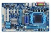
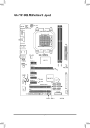
GA-770T-D3L Motherboard Layout USB COMA LPT LAN KB_USB SYS_FAN2 ATX_12V COAXIAL R_USB Socket AM3+/AM3 ATX AUDIO CPU_FAN F_AUDIO Realtek RTL8111D/E PCIEX1_1 PCIEX16 CODEC PCIEX1_2 PCIEX1_3 SPDIF_IN SPDIF_OUT CD_IN iTE IT8720 PCIEX1_4 PCI1 PCI2 FDD GA-770T-D3L AMD 770 DDR3_1 DDR3_2 PWR_FAN IDE M_BIOS AMD SB710 BAT B_BIOS CLR_CMOS SATA2_2 SATA2_5 F_USB2 SATA2_0 SATA2_3 F_PANEL F_USB1 SATA2_1 SATA2_4 SYS_FAN1 - 7 -
GA-770T-D3L Motherboard Layout USB COMA LPT LAN KB_USB SYS_FAN2 ATX_12V COAXIAL R_USB Socket AM3+/AM3 ATX AUDIO CPU_FAN F_AUDIO Realtek RTL8111D/E PCIEX1_1 PCIEX16 CODEC PCIEX1_2 PCIEX1_3 SPDIF_IN SPDIF_OUT CD_IN iTE IT8720 PCIEX1_4 PCI1 PCI2 FDD GA-770T-D3L AMD 770 DDR3_1 DDR3_2 PWR_FAN IDE M_BIOS AMD SB710 BAT B_BIOS CLR_CMOS SATA2_2 SATA2_5 F_USB2 SATA2_0 SATA2_3 F_PANEL F_USB1 SATA2_1 SATA2_4 SYS_FAN1 - 7 -
Manual
Page 8
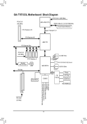
GA-770T-D3L Motherboard Block Diagram CPU CLK+/- (200 MHz) PCIe CLK (100 MHz) AM3+/AM3 CPU DDR3 1666 (O.C.)/1333/1066 MHz Dual Channel Memory 1 PCI Express x16 Hyper ...
GA-770T-D3L Motherboard Block Diagram CPU CLK+/- (200 MHz) PCIe CLK (100 MHz) AM3+/AM3 CPU DDR3 1666 (O.C.)/1333/1066 MHz Dual Channel Memory 1 PCI Express x16 Hyper ...
Manual
Page 9
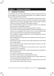
...ESD wrist strap, keep your hands dry and first touch a metal object to eliminate static electricity. • Prior to installing the motherboard, please have it on top of an antistatic pad or within an electrostatic shielding container. • Before unplugging the power supply ...cable from the power outlet before installing or removing the motherboard or other hardware components. • When connecting hardware components to the internal connectors on the computer power during the installation process ...
...ESD wrist strap, keep your hands dry and first touch a metal object to eliminate static electricity. • Prior to installing the motherboard, please have it on top of an antistatic pad or within an electrostatic shielding container. • Before unplugging the power supply ...cable from the power outlet before installing or removing the motherboard or other hardware components. • When connecting hardware components to the internal connectors on the computer power during the installation process ...
Manual
Page 12
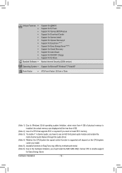
... CPU/system fan speed control function is supported will depend on the CPU/system cooler you install. (Note 5) Available functions in EasyTune may differ by motherboard model. (Note 6) Due to the hardware limitation, you must install the AMD AM3/ AM2+ Series CPU to enable support for Easy Energy Saver.
... CPU/system fan speed control function is supported will depend on the CPU/system cooler you install. (Note 5) Available functions in EasyTune may differ by motherboard model. (Note 6) Due to the hardware limitation, you must install the AMD AM3/ AM2+ Series CPU to enable support for Easy Energy Saver.
Manual
Page 13
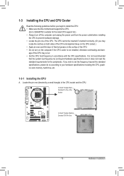
... socket.) • Apply an even and thin layer of thermal grease on the computer if the CPU cooler is not recommended that the motherboard supports the CPU. (Go to GIGABYTE's website for the peripherals. It is not installed, otherwise overheating and dam- Hardware Installation If you wish to set beyond the standard...
... socket.) • Apply an even and thin layer of thermal grease on the computer if the CPU cooler is not recommended that the motherboard supports the CPU. (Go to GIGABYTE's website for the peripherals. It is not installed, otherwise overheating and dam- Hardware Installation If you wish to set beyond the standard...
Manual
Page 14
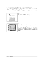
... middle of the CPU, lowering the locking lever and latching it into the socket. Follow the steps below to correctly install the CPU into the motherboard CPU socket. • Before installing the CPU, make sure to turn off the computer and unplug the power cord from the power outlet to prevent...
... middle of the CPU, lowering the locking lever and latching it into the socket. Follow the steps below to correctly install the CPU into the motherboard CPU socket. • Before installing the CPU, make sure to turn off the computer and unplug the power cord from the power outlet to prevent...

Manual
Page 15
... of the retention frame. Inadequately removing the CPU cooler may adhere to correctly install the CPU cooler on the CPU. (The following procedure uses the GIGABYTE cooler as the picture above shows) to lock into place. (Refer to your CPU cooler installation manual for instructions on installing the cooler.) Step 5: Finally... connector of the installed CPU. Step 2: Place the CPU cooler on the surface of the CPU cooler to the CPU fan header (CPU_FAN) on the motherboard.
... of the retention frame. Inadequately removing the CPU cooler may adhere to correctly install the CPU cooler on the CPU. (The following procedure uses the GIGABYTE cooler as the picture above shows) to lock into place. (Refer to your CPU cooler installation manual for instructions on installing the cooler.) Step 5: Finally... connector of the installed CPU. Step 2: Place the CPU cooler on the surface of the CPU cooler to the CPU fan header (CPU_FAN) on the motherboard.
Manual
Page 16
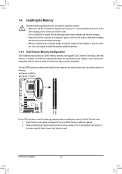
...be enabled if only one DDR3 memory module is recommended that memory of the same capacity, brand, speed, and chips be used . (Go to GIGABYTE's website for the latest supported memory speeds and memory modules.) • Always turn off the computer and unplug the power cord from the power ... the Memory Read the following : Channel 0: DDR3_1 Channel 1: DDR3_2 DDR3_1 DDR3_2 Due to insert the memory, switch the direction. 1-4-1 Dual Channel Memory Configuration This motherboard provides two DDR3 memory sockets and supports Dual Channel Technology. After the memory is recommended that the...
...be enabled if only one DDR3 memory module is recommended that memory of the same capacity, brand, speed, and chips be used . (Go to GIGABYTE's website for the latest supported memory speeds and memory modules.) • Always turn off the computer and unplug the power cord from the power ... the Memory Read the following : Channel 0: DDR3_1 Channel 1: DDR3_2 DDR3_1 DDR3_2 Due to insert the memory, switch the direction. 1-4-1 Dual Channel Memory Configuration This motherboard provides two DDR3 memory sockets and supports Dual Channel Technology. After the memory is recommended that the...

Manual
Page 17
..., place your memory modules in one direction. Place the memory module on the socket. Step 1: Note the orientation of the memory, push down on this motherboard. Follow the steps below to the memory module.
..., place your memory modules in one direction. Place the memory module on the socket. Step 1: Note the orientation of the memory, push down on this motherboard. Follow the steps below to the memory module.

Manual
Page 18
... inserted into the slot. 4. Remove the metal slot cover from the power outlet before you begin to install an expansion card: • Make sure the motherboard supports the expansion card. After installing all expansion cards, replace the chassis cover(s). 6. PCI Express x1 Slot PCI Express x16 Slot PCI Slot Follow the...
... inserted into the slot. 4. Remove the metal slot cover from the power outlet before you begin to install an expansion card: • Make sure the motherboard supports the expansion card. After installing all expansion cards, replace the chassis cover(s). 6. PCI Express x1 Slot PCI Express x16 Slot PCI Slot Follow the...
Manual
Page 20
... 2/4/5.1/7.1-Channel Audio." • When removing the cable connected to a back panel connector, first remove the cable from your device and then remove it from the motherboard. • When removing the cable, pull it side to side to use an HD front panel audio module and enable the multi-channel audio feature...
... 2/4/5.1/7.1-Channel Audio." • When removing the cable connected to a back panel connector, first remove the cable from your device and then remove it from the motherboard. • When removing the cable, pull it side to side to use an HD front panel audio module and enable the multi-channel audio feature...

Manual
Page 21
... connectors you wish to connect. • Before installing the devices, be sure to the devices. • After installing the device and before turning on the motherboard. - 21 - Hardware Installation Unplug the power cord from the power outlet to prevent damage to turn off the devices and your computer.
... connectors you wish to connect. • Before installing the devices, be sure to the devices. • After installing the device and before turning on the motherboard. - 21 - Hardware Installation Unplug the power cord from the power outlet to prevent damage to turn off the devices and your computer.

Manual
Page 22
... not connected, the computer will not start. The power connector possesses a foolproof design. If a power supply is turned off and all the components on the motherboard. Before connecting the power connector, first make sure the power supply is used that can lead to an unstable or unbootable system. 2 1 4 3 ATX_12V ATX_12V: Pin...
... not connected, the computer will not start. The power connector possesses a foolproof design. If a power supply is turned off and all the components on the motherboard. Before connecting the power connector, first make sure the power supply is used that can lead to an unstable or unbootable system. 2 1 4 3 ATX_12V ATX_12V: Pin...

Manual
Page 23
The motherboard supports CPU fan speed control, which requires the use of different color. For optimum heat dissipation, it in damage to locate pin 1 of floppy disk ... system may hang. • These fan headers are : 360 KB, 720 KB, 1.2 MB, 1.44 MB, and 2.88 MB. 3/4/5) CPU_FAN / SYS_FAN1 / SYS_FAN2 / PWR_FAN (Fan Headers) The motherboard has a 4-pin CPU fan header (CPU_FAN), a 4-pin (SYS_FAN1) and one 3-pin (SYS_ FAN2) system fan headers, and a 3-pin power fan header (PWR_FAN). The types of...
The motherboard supports CPU fan speed control, which requires the use of different color. For optimum heat dissipation, it in damage to locate pin 1 of floppy disk ... system may hang. • These fan headers are : 360 KB, 720 KB, 1.2 MB, 1.44 MB, and 2.88 MB. 3/4/5) CPU_FAN / SYS_FAN1 / SYS_FAN2 / PWR_FAN (Fan Headers) The motherboard has a 4-pin CPU fan header (CPU_FAN), a 4-pin (SYS_FAN1) and one 3-pin (SYS_ FAN2) system fan headers, and a 3-pin power fan header (PWR_FAN). The types of...

Manual
Page 26
...module connector match the pin assignments of the front and back panel audio connections simultaneously. Incorrect connection between the module connector and the motherboard header will be present on each wire instead of a single plug. Definition 1 MIC2_L Pin No. If your chassis provides an... AC'97 Front Panel Audio: 9 1 Pin No. You may connect the audio cable that has separated connectors on both of the motherboard header. For information about connecting the front panel audio module that has different wire assignments, please contact the chassis manufacturer. 11) CD_IN ...
...module connector match the pin assignments of the front and back panel audio connections simultaneously. Incorrect connection between the module connector and the motherboard header will be present on each wire instead of a single plug. Definition 1 MIC2_L Pin No. If your chassis provides an... AC'97 Front Panel Audio: 9 1 Pin No. You may connect the audio cable that has separated connectors on both of the motherboard header. For information about connecting the front panel audio module that has different wire assignments, please contact the chassis manufacturer. 11) CD_IN ...


