Manual
Page 3
... or download the information on/from the Support\Motherboard\Technology Guide page on your motherboard revision before updating motherboard BIOS, drivers, or when looking for technical information. No part of this product, GIGABYTE provides the following types of this manual may be reproduced, copied, translated, transmitted, or published in this manual is...
... or download the information on/from the Support\Motherboard\Technology Guide page on your motherboard revision before updating motherboard BIOS, drivers, or when looking for technical information. No part of this product, GIGABYTE provides the following types of this manual may be reproduced, copied, translated, transmitted, or published in this manual is...
Manual
Page 4
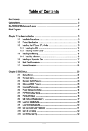
...GA-73VM-S2 Motherboard Layout 7 Block Diagram...8 Chapter 1 Hardware Installation 9 1-1 Installation Precautions 9 1-2 Product Specifications 10 1-3 Installing the CPU and CPU Cooler 13 1-3-1 Installing the CPU 13 1-3-2 Installing the CPU Cooler 15 1-4 Installing the Memory 16 1-4-1 Installing a Memory 16 1-5 Installing an Expansion Card 17 1-6 Back Panel Connectors 18 1-7 Internal Connectors 20 Chapter 2 BIOS... Setup 29 2-1 Startup Screen 30 2-2 The Main Menu 31 2-3 Standard CMOS Features 33 2-4 Advanced BIOS Features 35 2-5 IntegratedPeripherals ...
...GA-73VM-S2 Motherboard Layout 7 Block Diagram...8 Chapter 1 Hardware Installation 9 1-1 Installation Precautions 9 1-2 Product Specifications 10 1-3 Installing the CPU and CPU Cooler 13 1-3-1 Installing the CPU 13 1-3-2 Installing the CPU Cooler 15 1-4 Installing the Memory 16 1-4-1 Installing a Memory 16 1-5 Installing an Expansion Card 17 1-6 Back Panel Connectors 18 1-7 Internal Connectors 20 Chapter 2 BIOS... Setup 29 2-1 Startup Screen 30 2-2 The Main Menu 31 2-3 Standard CMOS Features 33 2-4 Advanced BIOS Features 35 2-5 IntegratedPeripherals ...
Manual
Page 5
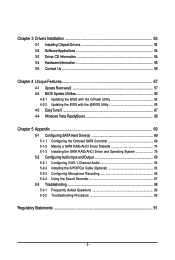
... 54 3-3 Driver CD Information 54 3-4 Hardware Information 55 3-5 Contact Us ...55 Chapter 4 Unique Features 57 4-1 Xpress Recovery2 57 4-2 BIOS Update Utilities 62 4-2-1 Updating the BIOS with the Q-Flash Utility 62 4-2-2 Updating the BIOS with the @BIOS Utility 65 4-3 EasyTune 5 ...67 4-4 Windows Vista ReadyBoost 68 Chapter 5 Appendix ...69 5-1 Configuring SATA Hard Drive(s 69 5-1-1 Configuring the...
... 54 3-3 Driver CD Information 54 3-4 Hardware Information 55 3-5 Contact Us ...55 Chapter 4 Unique Features 57 4-1 Xpress Recovery2 57 4-2 BIOS Update Utilities 62 4-2-1 Updating the BIOS with the Q-Flash Utility 62 4-2-2 Updating the BIOS with the @BIOS Utility 65 4-3 EasyTune 5 ...67 4-4 Windows Vista ReadyBoost 68 Chapter 5 Appendix ...69 5-1 Configuring SATA Hard Drive(s 69 5-1-1 Configuring the...
Manual
Page 7
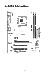
GA-73VM-S2 Motherboard Layout COMA KB_MS ATX_12V CPU_FAN LGA775 DDRII1 DDRII2 LPT LAN VGA GA-73VM-S2 R_USB USB RTL8201N AUDIO F_AUDIO BIOS CLR_CMOS PCIE_1 NVIDIA® GeForce 7050/ nForce 610i IT8718 PCIE_16 PCI1 SPDIF_O CODEC CD_IN PCI2 F_USB1 FDD F_USB2 SATAII0 SATAII2 SATAII1 SATAII3 ATX IDE BAT CI PWR_LED F_PANEL SYS_FAN - 7 -
GA-73VM-S2 Motherboard Layout COMA KB_MS ATX_12V CPU_FAN LGA775 DDRII1 DDRII2 LPT LAN VGA GA-73VM-S2 R_USB USB RTL8201N AUDIO F_AUDIO BIOS CLR_CMOS PCIE_1 NVIDIA® GeForce 7050/ nForce 610i IT8718 PCIE_16 PCI1 SPDIF_O CODEC CD_IN PCI2 F_USB1 FDD F_USB2 SATAII0 SATAII2 SATAII1 SATAII3 ATX IDE BAT CI PWR_LED F_PANEL SYS_FAN - 7 -
Manual
Page 8
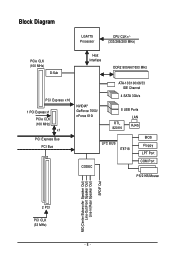
Block Diagram LGA775 Processor CPU CLK+/(333/266/200 MHz) PCIe CLK (100 MHz) D-Sub Host Interface DDR2 800/667/533 MHz PCI Express x16 1 PCI Express x1 PCIe CLK (100 MHz) x1 PCI Express Bus PCI Bus ATA-133/100/66/33 IDE Channel 4 SATA 3Gb/s NVIDIA® GeForce 7050/ nForce 610i 8 USB Ports RTL 8201N LAN RJ45 LPC BUS IT8718 CODEC BIOS Floppy LPT Port COM Port PS/2 KB/Mouse MIC(Center/Subwoofer Speaker Out) Line-Out(Front Speaker Out) Line-In(Rear Speaker Out) SPDIF Out 2 PCI PCI CLK (33 MHz) - 8 -
Block Diagram LGA775 Processor CPU CLK+/(333/266/200 MHz) PCIe CLK (100 MHz) D-Sub Host Interface DDR2 800/667/533 MHz PCI Express x16 1 PCI Express x1 PCIe CLK (100 MHz) x1 PCI Express Bus PCI Bus ATA-133/100/66/33 IDE Channel 4 SATA 3Gb/s NVIDIA® GeForce 7050/ nForce 610i 8 USB Ports RTL 8201N LAN RJ45 LPC BUS IT8718 CODEC BIOS Floppy LPT Port COM Port PS/2 KB/Mouse MIC(Center/Subwoofer Speaker Out) Line-Out(Front Speaker Out) Line-In(Rear Speaker Out) SPDIF Out 2 PCI PCI CLK (33 MHz) - 8 -
Manual
Page 11
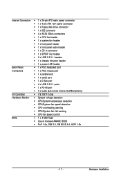
...; CPU/System temperature detection Š CPU/System fan speed detection Š CPU overheating warning Š CPU/System fan fail warning Š CPU fan speed control BIOS Š 1 x 4 Mbit flash Š Use of licensed AWARD BIOS Š PnP 1.0a, DMI 2.0, SM BIOS 2.4, ACPI 1.0b - 11 - Hardware Installation
...; CPU/System temperature detection Š CPU/System fan speed detection Š CPU overheating warning Š CPU/System fan fail warning Š CPU fan speed control BIOS Š 1 x 4 Mbit flash Š Use of licensed AWARD BIOS Š PnP 1.0a, DMI 2.0, SM BIOS 2.4, ACPI 1.0b - 11 - Hardware Installation
Manual
Page 12
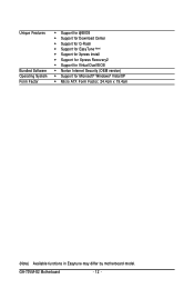
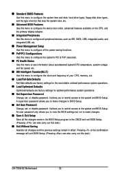
GA-73VM-S2 Motherboard - 12 - Unique Features Bundled Software Operating System Form Factor Š Support for @BIOS Š Support for Download Center Š Support for Q-Flash Š Support for EasyTune (Note) Š Support for Xpress Install Š Support for Xpress Recovery2 Š Support for Virtual Dual BIOS Š Norton Internet Security (OEM version) Š Support for Microsoft® Windows® Vista/XP Š Micro ATX Form Factor; 24.4cm x 19.4cm (Note) Available functions in Easytune may differ by motherboard model.
GA-73VM-S2 Motherboard - 12 - Unique Features Bundled Software Operating System Form Factor Š Support for @BIOS Š Support for Download Center Š Support for Q-Flash Š Support for EasyTune (Note) Š Support for Xpress Install Š Support for Xpress Recovery2 Š Support for Virtual Dual BIOS Š Norton Internet Security (OEM version) Š Support for Microsoft® Windows® Vista/XP Š Micro ATX Form Factor; 24.4cm x 19.4cm (Note) Available functions in Easytune may differ by motherboard model.
Manual
Page 17
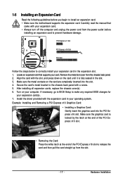
... chassis back panel with your operating system. Align the card with the expansion card in the expansion slot. 1. If necessary, go to BIOS Setup to make any required BIOS changes for your computer. Install the driver provided with the slot, and press down on the card are completely inserted into the PCI...
... chassis back panel with your operating system. Align the card with the expansion card in the expansion slot. 1. If necessary, go to BIOS Setup to make any required BIOS changes for your computer. Install the driver provided with the slot, and press down on the card are completely inserted into the PCI...

Manual
Page 24
... state or powered off your computer and unplug the power cord. 2. Replace the battery when the battery voltage drops to keep the values (such as BIOS configurations, date, and time information) in accordance with an equivalent one minute. (Or use a metal object like a screwdriver to touch the positive and negative terminals... are not able to indicate system power status. Gently remove the battery from the battery holder and wait for 5 seconds.) 3. Plug in S1 sleep state. GA-73VM-S2 Motherboard - 24 -
... state or powered off your computer and unplug the power cord. 2. Replace the battery when the battery voltage drops to keep the values (such as BIOS configurations, date, and time information) in accordance with an equivalent one minute. (Or use a metal object like a screwdriver to touch the positive and negative terminals... are not able to indicate system power status. Gently remove the battery from the battery holder and wait for 5 seconds.) 3. Plug in S1 sleep state. GA-73VM-S2 Motherboard - 24 -
Manual
Page 25
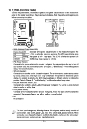
... • PW (Power Switch): Connects to the speaker on the chassis front panel. When connecting your system using the power switch (refer to Chapter 2, "BIOS Setup," "Power Management Setup," for information about beep codes. • HD (IDE Hard Drive Activity LED) Connects to perform a normal restart. • ... switch to restart the computer if the computer freezes and fails to the hard drive activity LED on when the system is detected, the BIOS may differ by issuing a beep code. 10) F_PANEL (Front Panel Header) Connect the power switch, reset switch, speaker and system status...
... • PW (Power Switch): Connects to the speaker on the chassis front panel. When connecting your system using the power switch (refer to Chapter 2, "BIOS Setup," "Power Management Setup," for information about beep codes. • HD (IDE Hard Drive Activity LED) Connects to perform a normal restart. • ... switch to restart the computer if the computer freezes and fails to the hard drive activity LED on when the system is detected, the BIOS may differ by issuing a beep code. 10) F_PANEL (Front Panel Header) Connect the power switch, reset switch, speaker and system status...
Manual
Page 28
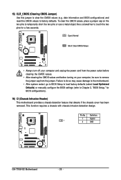
...) CLR_CMOS (Clearing CMOS Jumper) Use this jumper to remove the jumper cap from the jumper. date information and BIOS configurations) and reset the CMOS values to Chapter 2, "BIOS Setup," for a few seconds. Definition 1 Signal 1 2 GND GA-73VM-S2 Motherboard - 28 - Failure to do so may cause damage to the motherboard. • After system restart, go...
...) CLR_CMOS (Clearing CMOS Jumper) Use this jumper to remove the jumper cap from the jumper. date information and BIOS configurations) and reset the CMOS values to Chapter 2, "BIOS Setup," for a few seconds. Definition 1 Signal 1 2 GND GA-73VM-S2 Motherboard - 28 - Failure to do so may cause damage to the motherboard. • After system restart, go...
Manual
Page 29
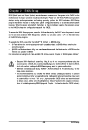
... and easily upgrade or back up BIOS without entering the operating system. • @BIOS is recommended that searches and downloads the latest version of BIOS, it with caution. To upgrade the BIOS, use either the GIGABYTE Q-Flash or @BIOS utility. • Q-Flash allows the user to Chapter 4, "BIOS Update Utilities." • Because BIOS flashing is potentially risky, if...
... and easily upgrade or back up BIOS without entering the operating system. • @BIOS is recommended that searches and downloads the latest version of BIOS, it with caution. To upgrade the BIOS, use either the GIGABYTE Q-Flash or @BIOS utility. • Q-Flash allows the user to Chapter 4, "BIOS Update Utilities." • Because BIOS flashing is potentially risky, if...
Manual
Page 30
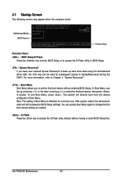
... system will still be used for one time only. GA-73VM-S2 F1a . . . . : BIOS Setup/Q-Flash : XpressRecovery2 : Boot Menu : Qflash 10/31/2007-NF73-6A61NG03C-00 Function Keys Function Keys: : BIOS Setup/Q-Flash Press the key to enter BIOS Setup or to access the Q-Flash utility in BIOS Setup. : Xpress Recovery2 If you to set the first...
... system will still be used for one time only. GA-73VM-S2 F1a . . . . : BIOS Setup/Q-Flash : XpressRecovery2 : Boot Menu : Qflash 10/31/2007-NF73-6A61NG03C-00 Function Keys Function Keys: : BIOS Setup/Q-Flash Press the key to enter BIOS Setup or to access the Q-Flash utility in BIOS Setup. : Xpress Recovery2 If you to set the first...
Manual
Page 31
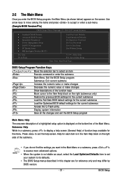
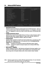
...options. • When the system is displayed on the bottom line of the Main Menu. BIOS Setup Program Function Keys Move the selection bar to select an item Execute command or enter the submenu Main ...Menu: Exit the BIOS Setup program Submenus: Exit current submenu Increase the numeric value or make changes Decrease the ... the right side of the submenu. • If you do not find the settings you enter the BIOS Setup program, the Main Menu (as usual, select the Load Optimized Defaults item to set your system ...
...options. • When the system is displayed on the bottom line of the Main Menu. BIOS Setup Program Function Keys Move the selection bar to select an item Execute command or enter the submenu Main ...Menu: Exit the BIOS Setup program Submenus: Exit current submenu Increase the numeric value or make changes Decrease the ... the right side of the submenu. • If you do not find the settings you enter the BIOS Setup program, the Main Menu (as usual, select the Load Optimized Defaults item to set your system ...
Manual
Page 32
... restrict access to the system and BIOS Setup. An user password only allows you to make changes. „ Save & Exit Setup Save all the changes made in the BIOS Setup program to the CMOS and exit BIOS Setup. (Pressing can also carry out this task.) GA-73VM-S2 Motherboard - 32 - A supervisor... password allows you to view the BIOS settings but not to make changes in effect. Pressing to the ...
... restrict access to the system and BIOS Setup. An user password only allows you to make changes. „ Save & Exit Setup Save all the changes made in the BIOS Setup program to the CMOS and exit BIOS Setup. (Pressing can also carry out this task.) GA-73VM-S2 Motherboard - 32 - A supervisor... password allows you to view the BIOS settings but not to make changes in effect. Pressing to the ...
Manual
Page 33
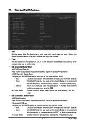
... to manually enter the specifications of the device during the POST for faster system startup. Options are : Auto (default), CHS, LBA, Large. BIOS Setup Time Sets the system time. IDE Channel 0 Master/Slave IDE HDD Auto-Detection Press to autodetect the parameters of the IDE/SATA device on...Extended IDE Drive Configure your IDE/SATA devices by using one of the two methods below : • Auto • None • Manual Lets BIOS automatically detect IDE/SATA devices during the POST. (Default) If no IDE/SATA devices are used , set the time. Select the desired field and ...
... to manually enter the specifications of the device during the POST for faster system startup. Options are : Auto (default), CHS, LBA, Large. BIOS Setup Time Sets the system time. IDE Channel 0 Master/Slave IDE HDD Auto-Detection Press to autodetect the parameters of the IDE/SATA device on...Extended IDE Drive Configure your IDE/SATA devices by using one of the two methods below : • Auto • None • Manual Lets BIOS automatically detect IDE/SATA devices during the POST. (Default) If no IDE/SATA devices are used , set the time. Select the desired field and ...
Manual
Page 34
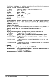
...floppy disk drive, set this item to specify whether the installed floppy disk drive is 3-mode floppy disk drive, a Japanese standard floppy disk drive. GA-73VM-S2 Motherboard - 34 - Options are : Disabled (default), Drive A. Typically, 640 KB will stop for the MS-DOS operating system. Options are :... None, 360K/5.25", 1.2M/5.25", 720K/3.5", 1.44M/3.5", 2.88M/3.5". Base Memory Also called conventional memory. All Errors Whenever the BIOS detects a non-fatal error the system boot will not stop . The following fields display your system. Memory These fields are read-only ...
...floppy disk drive, set this item to specify whether the installed floppy disk drive is 3-mode floppy disk drive, a Japanese standard floppy disk drive. GA-73VM-S2 Motherboard - 34 - Options are : Disabled (default), Drive A. Typically, 640 KB will stop for the MS-DOS operating system. Options are :... None, 360K/5.25", 1.2M/5.25", 720K/3.5", 1.44M/3.5", 2.88M/3.5". Base Memory Also called conventional memory. All Errors Whenever the BIOS detects a non-fatal error the system boot will not stop . The following fields display your system. Memory These fields are read-only ...
Manual
Page 35
...the sequence of loading the operating system from the available devices. Setup A password is only required for entering the BIOS Setup program. (Default) System A password is present only if you enter BIOS Setup. Options are: Floppy, LS120, Hard Disk, CDROM, ZIP, USB-FDD, USB-ZIP, USB-CDROM,...Reporting Technology) capability of the hard drive and to exit this item, set the password(s) under the Set Supervisor/User Password item in the BIOS Main Menu. Press to issue warnings when a third party hardware monitor utility is installed. (Default: Disabled) (Note) This item is ...
...the sequence of loading the operating system from the available devices. Setup A password is only required for entering the BIOS Setup program. (Default) System A password is present only if you enter BIOS Setup. Options are: Floppy, LS120, Hard Disk, CDROM, ZIP, USB-FDD, USB-ZIP, USB-CDROM,...Reporting Technology) capability of the hard drive and to exit this item, set the password(s) under the Set Supervisor/User Password item in the BIOS Main Menu. Press to issue warnings when a third party hardware monitor utility is installed. (Default: Disabled) (Note) This item is ...

Manual
Page 37
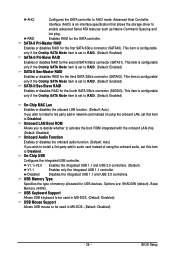
Init Display First Specifies the first initiation of system memory allocated solely for display. BIOS Setup Options are: 64M, 128M (default), 256M, Disabled. PCI Slot Sets the PCI graphics card as the first display. (Default) Onboard VGA Sets the onboard ...
Init Display First Specifies the first initiation of system memory allocated solely for display. BIOS Setup Options are: 64M, 128M (default), 256M, Disabled. PCI Slot Sets the PCI graphics card as the first display. (Default) Onboard VGA Sets the onboard ...
Manual
Page 39
... or disables the onboard audio function. (Default: Auto) If you wish to be used in network card instead of memory allocated for the SATA controller. BIOS Setup V1.1+V2.0 Enables the integrated USB 1.1 and USB 2.0 controllers. (Default) V1.1 Enables only the integrated USB 1.1 controller. USB Keyboard Support Allows USB keyboard to...
... or disables the onboard audio function. (Default: Auto) If you wish to be used in network card instead of memory allocated for the SATA controller. BIOS Setup V1.1+V2.0 Enables the integrated USB 1.1 and USB 2.0 controllers. (Default) V1.1 Enables only the integrated USB 1.1 controller. USB Keyboard Support Allows USB keyboard to...


