Manual
Page 1
GA-73PVM-S2H LGA775 socket motherboard for Intel® Core TM processor family/ Intel® Pentium® processor family/Intel® Celeron® processor family User's Manual Rev. 1004 12ME-73PVMS2H-1004R
GA-73PVM-S2H LGA775 socket motherboard for Intel® Core TM processor family/ Intel® Pentium® processor family/Intel® Celeron® processor family User's Manual Rev. 1004 12ME-73PVMS2H-1004R
Manual
Page 2
Motherboard GA-73PVM-S2H Oct. 11, 2007 Motherboard GA-73PVM-S2H Oct. 11, 2007
Motherboard GA-73PVM-S2H Oct. 11, 2007 Motherboard GA-73PVM-S2H Oct. 11, 2007
Manual
Page 3
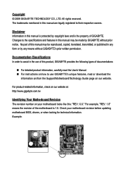
... to assist in this manual is protected by copyright laws and is the property of the motherboard is 1.0. Documentation Classifications In order to use of this product, GIGABYTE provides the following types of this manual may be reproduced, copied, translated, transmitted, or published... manual may be made by any means without prior notice. Check your motherboard looks like this manual are legally registered to the specifications and features in any form or by GIGABYTE without GIGABYTE's prior written permission. Changes to their respective owners. Example: All rights...
... to assist in this manual is protected by copyright laws and is the property of the motherboard is 1.0. Documentation Classifications In order to use of this product, GIGABYTE provides the following types of this manual may be reproduced, copied, translated, transmitted, or published... manual may be made by any means without prior notice. Check your motherboard looks like this manual are legally registered to the specifications and features in any form or by GIGABYTE without GIGABYTE's prior written permission. Changes to their respective owners. Example: All rights...
Manual
Page 4
Table of Contents Box Contents ...6 Optional Items...6 GA-73PVM-S2H Motherboard Layout 7 Block Diagram...8 Chapter 1 Hardware Installation 9 1-1 Installation Precautions 9 1-2 Product Specifications 10 1-3 Installing the CPU and CPU Cooler 13 1-3-1 Installing the CPU 13 1-3-2 Installing the CPU ...
Table of Contents Box Contents ...6 Optional Items...6 GA-73PVM-S2H Motherboard Layout 7 Block Diagram...8 Chapter 1 Hardware Installation 9 1-1 Installation Precautions 9 1-2 Product Specifications 10 1-3 Installing the CPU and CPU Cooler 13 1-3-1 Installing the CPU 13 1-3-2 Installing the CPU ...
Manual
Page 6
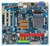
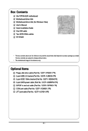
The box contents are for reference only. Box Contents GA-73PVM-S2H motherboard Motherboard driver disk Motherboard driver disk (for Windows Vista) User's Manual Quick Installation Guide One IDE cable Two SATA 3Gb/s cables I/O Shield • The box contents above are subject to change without notice. • The motherboard image is for reference only and the actual items...
The box contents are for reference only. Box Contents GA-73PVM-S2H motherboard Motherboard driver disk Motherboard driver disk (for Windows Vista) User's Manual Quick Installation Guide One IDE cable Two SATA 3Gb/s cables I/O Shield • The box contents above are subject to change without notice. • The motherboard image is for reference only and the actual items...
Manual
Page 7
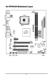
GA-73PVM-S2H Motherboard Layout KB_MS ATX_12V VGA DVI HDMI OPTICAL ESATA USB 1394 LAN USB RTL 8211B AUDIO F_AUDIO CD_IN PCIE_1 PCIE_16 CODEC PCI1 PCI2 SPDIF_IO F_USB3 F_USB1 F_USB2 LGA775 CPU_FAN ATX LPT GA-73PVM-S2H nVIDIA® GeForce 7100/ nForce 630i IDE SATAII1 SATAII0 SATAII2 DDRII1 DDRII2 BIOS TSB43AB23 IT8718 CLR_CMOS CI BATTERY F1_1394 FDD SYS_FAN PWR_LED COMA F_PANEL - 7 -
GA-73PVM-S2H Motherboard Layout KB_MS ATX_12V VGA DVI HDMI OPTICAL ESATA USB 1394 LAN USB RTL 8211B AUDIO F_AUDIO CD_IN PCIE_1 PCIE_16 CODEC PCI1 PCI2 SPDIF_IO F_USB3 F_USB1 F_USB2 LGA775 CPU_FAN ATX LPT GA-73PVM-S2H nVIDIA® GeForce 7100/ nForce 630i IDE SATAII1 SATAII0 SATAII2 DDRII1 DDRII2 BIOS TSB43AB23 IT8718 CLR_CMOS CI BATTERY F1_1394 FDD SYS_FAN PWR_LED COMA F_PANEL - 7 -
Manual
Page 9
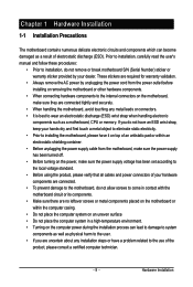
...for warranty validation. • Always remove the AC power by your hardware components are connected. • To prevent damage to the motherboard, do not have an ESD wrist strap, keep your hands dry and first touch a metal object to eliminate static electricity. •...) wrist strap when handling electronic components such as a result of electrostatic discharge (ESD). Chapter 1 Hardware Installation 1-1 Installation Precautions The motherboard contains numerous delicate electronic circuits and components which can lead to damage to system components as well as physical harm to the user. ...
...for warranty validation. • Always remove the AC power by your hardware components are connected. • To prevent damage to the motherboard, do not have an ESD wrist strap, keep your hands dry and first touch a metal object to eliminate static electricity. •...) wrist strap when handling electronic components such as a result of electrostatic discharge (ESD). Chapter 1 Hardware Installation 1-1 Installation Precautions The motherboard contains numerous delicate electronic circuits and components which can lead to damage to system components as well as physical harm to the user. ...
Manual
Page 10
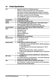
...; Pentium® 4 processor Extreme Edition/Intel ® Pentium® 4 processor/ Intel® Celeron® processor in the LGA 775 package (Go to GIGABYTE's website for the latest CPU support list.) L2 cache varies with CPU 1333/1066/800 MHz FSB nVIDIA® GeForce 7100...133/100/66/33 and up to 2 IDE devices iTE IT8718 chip: - 1 x floppy disk drive connector supporting up to the internal USB headers) GA-73PVM-S2H Motherboard - 10 - TSB43AB23 chip Up to 2 IEEE 1394a ports (1 on the back panel, 1 via the USB brackets connected to 1 SA TA 3Gb...
...; Pentium® 4 processor Extreme Edition/Intel ® Pentium® 4 processor/ Intel® Celeron® processor in the LGA 775 package (Go to GIGABYTE's website for the latest CPU support list.) L2 cache varies with CPU 1333/1066/800 MHz FSB nVIDIA® GeForce 7100...133/100/66/33 and up to 2 IDE devices iTE IT8718 chip: - 1 x floppy disk drive connector supporting up to the internal USB headers) GA-73PVM-S2H Motherboard - 10 - TSB43AB23 chip Up to 2 IEEE 1394a ports (1 on the back panel, 1 via the USB brackets connected to 1 SA TA 3Gb...
Manual
Page 12
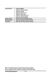
GA-73PVM-S2H Motherboard - 12 - Unique Features Bundled Software Operating System Form Factor Support for @BIOS Support for Download Center Support for Q-Flash Support for ... Form Factor; 24.4cm x 22.0cm (Note 1) The DVI-D port does not support D-Sub connection by adapter. (Note 2) Available functions in Easytune may differ by motherboard model.
GA-73PVM-S2H Motherboard - 12 - Unique Features Bundled Software Operating System Form Factor Support for @BIOS Support for Download Center Support for Q-Flash Support for ... Form Factor; 24.4cm x 22.0cm (Note 1) The DVI-D port does not support D-Sub connection by adapter. (Note 2) Available functions in Easytune may differ by motherboard model.

Manual
Page 13
Locate the alignment keys on the motherboard CPU socket and the notches on the CPU - 13 - LGA775 CPU Socket Alignment Key LGA 775 CPU Alignment Key Pin One Corner of the CPU. &#... requirements for the latest CPU support list.) • Always turn on the computer if the CPU cooler is not recom- mended that the motherboard supports the CPU. (Go to GIGABYTE's website for the peripherals. 1-3 Installing the CPU and CPU Cooler Read the following guidelines before you begin to install the CPU: •...
Locate the alignment keys on the motherboard CPU socket and the notches on the CPU - 13 - LGA775 CPU Socket Alignment Key LGA 775 CPU Alignment Key Pin One Corner of the CPU. &#... requirements for the latest CPU support list.) • Always turn on the computer if the CPU cooler is not recom- mended that the motherboard supports the CPU. (Go to GIGABYTE's website for the peripherals. 1-3 Installing the CPU and CPU Cooler Read the following guidelines before you begin to install the CPU: •...
Manual
Page 14
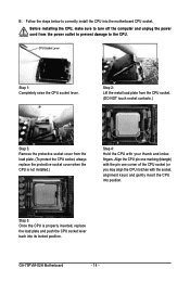
... from the CPU socket. (DO NOT touch socket contacts.) Step 3: Remove the protective socket cover from the power outlet to prevent damage to the CPU. GA-73PVM-S2H Motherboard - 14 - B. Before installing the CPU, make sure to correctly install the CPU into position. Step 5: Once the CPU is not installed.) Step 4: Hold the CPU...
... from the CPU socket. (DO NOT touch socket contacts.) Step 3: Remove the protective socket cover from the power outlet to prevent damage to the CPU. GA-73PVM-S2H Motherboard - 14 - B. Before installing the CPU, make sure to correctly install the CPU into position. Step 5: Once the CPU is not installed.) Step 4: Hold the CPU...

Manual
Page 15
... sign on the male push pin. (Turning the push pin along the direction of the CPU cooler to the CPU fan header (CPU_FAN) on the motherboard. Step 4: You should hear a "click" when pushing down on the push pins diagonally. Step 6: Finally, attach the power connector of arrow is to remove the... cooler, on the contrary, is to install.) Step 3: Place the cooler atop the CPU, aligning the four push pins through the pin holes on the motherboard. Use extreme care when removing the CPU cooler because the thermal grease/tape between the CPU cooler and CPU may damage the CPU. - 15 - Inadequately...
... sign on the male push pin. (Turning the push pin along the direction of the CPU cooler to the CPU fan header (CPU_FAN) on the motherboard. Step 4: You should hear a "click" when pushing down on the push pins diagonally. Step 6: Finally, attach the power connector of arrow is to remove the... cooler, on the contrary, is to install.) Step 3: Place the cooler atop the CPU, aligning the four push pins through the pin holes on the motherboard. Use extreme care when removing the CPU cooler because the thermal grease/tape between the CPU cooler and CPU may damage the CPU. - 15 - Inadequately...
Manual
Page 16
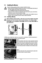
... insert it can be used. (Go to GIGABYTE's website for the latest memory support list.) • Always turn off the computer and unplug the power cord from the power outlet to prevent damage to insert the memory, switch the direction. GA-73PVM-S2H Motherboard - 16 - If you begin to install ...DDR2 DIMMs on this motherboard. Step 1: Note the orientation of the memory socket. Step 2: The clips at both ends of the ...
... insert it can be used. (Go to GIGABYTE's website for the latest memory support list.) • Always turn off the computer and unplug the power cord from the power outlet to prevent damage to insert the memory, switch the direction. GA-73PVM-S2H Motherboard - 16 - If you begin to install ...DDR2 DIMMs on this motherboard. Step 1: Note the orientation of the memory socket. Step 2: The clips at both ends of the ...
Manual
Page 17
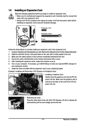
... hardware damage. PCI Express x1 Slot PCI Express x16 Slot PCI Slot Follow the steps below to install an expansion card: • Make sure the motherboard supports the expansion card. Make sure the metal contacts on the card are completely inserted into the PCI Express x16 slot. After installing all expansion...
... hardware damage. PCI Express x1 Slot PCI Express x16 Slot PCI Slot Follow the steps below to install an expansion card: • Make sure the motherboard supports the expansion card. Make sure the metal contacts on the card are completely inserted into the PCI Express x16 slot. After installing all expansion...
Manual
Page 18
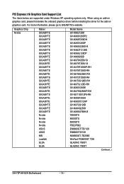
... delete the onboard graphics driver before installing the driver for the add-on graphics card. Graphics Chip Nvidia Maker GIGABYTE GIGABYTE GIGABYTE GIGABYTE GIGABYTE GIGABYTE GIGABYTE GIGABYTE GIGABYTE GIGABYTE GIGABYTE GIGABYTE GIGABYTE GIGABYTE GIGABYTE GIGABYTE GIGABYTE GIGABYTE GIGABYTE GIGABYTE GIGABYTE GIGABYTE GIGABYTE GIGABYTE Nvidia Nvidia Nvidia Nvidia ASUS ASUS MSI Leadtek ELSA ELSA Model Name GV-NX62128D GV-NX66128DP2 GV-NX68T256DH GV-NX55128DP.../128 EN6600/TD/128 NX6800GT-TD256E WinFast PX6600GT TDH GLADIAC 760GT GLADIAC 790GT (Continued...) GA-73PVM-S2H Motherboard - 18 -
... delete the onboard graphics driver before installing the driver for the add-on graphics card. Graphics Chip Nvidia Maker GIGABYTE GIGABYTE GIGABYTE GIGABYTE GIGABYTE GIGABYTE GIGABYTE GIGABYTE GIGABYTE GIGABYTE GIGABYTE GIGABYTE GIGABYTE GIGABYTE GIGABYTE GIGABYTE GIGABYTE GIGABYTE GIGABYTE GIGABYTE GIGABYTE GIGABYTE GIGABYTE GIGABYTE Nvidia Nvidia Nvidia Nvidia ASUS ASUS MSI Leadtek ELSA ELSA Model Name GV-NX62128D GV-NX66128DP2 GV-NX68T256DH GV-NX55128DP.../128 EN6600/TD/128 NX6800GT-TD256E WinFast PX6600GT TDH GLADIAC 760GT GLADIAC 790GT (Continued...) GA-73PVM-S2H Motherboard - 18 -

Manual
Page 20
... Device and then click Set Default. D-Sub Port The D-Sub port supports a 15-pin D-Sub connector. Connect the HDMI audio/ video device to this port. GA-73PVM-S2H Motherboard - 20 - Connect a monitor that supports D-Sub connection to this port. Connect a monitor that supports DVI-D connection to this port. 1-6 Back Panel Connectors PS/2 Keyboard and...
... Device and then click Set Default. D-Sub Port The D-Sub port supports a 15-pin D-Sub connector. Connect the HDMI audio/ video device to this port. GA-73PVM-S2H Motherboard - 20 - Connect a monitor that supports D-Sub connection to this port. Connect a monitor that supports DVI-D connection to this port. 1-6 Back Panel Connectors PS/2 Keyboard and...

Manual
Page 21
... configuration. Optical S/PDIF Out Connector This connector provides digital audio out to an external audio system that your device and then remove it from the motherboard. • When removing the cable, pull it side to side to connect an external SA TA device or a SATA port multiplier. The following describes the...
... configuration. Optical S/PDIF Out Connector This connector provides digital audio out to an external audio system that your device and then remove it from the motherboard. • When removing the cable, pull it side to side to connect an external SA TA device or a SATA port multiplier. The following describes the...

Manual
Page 22
... Non-protected contents HD-DVD Blu-ray Suitable Resolution Windows XP Windows Vista 1920 x 1080p 1920 x 1080p 1920 x 1080p 1920 x 1080p 1920 x 1080p 1920 x 1080p GA-73PVM-S2H Motherboard - 22 - Dual Display Combination DVI-D + D-Sub DVI-D + HDMI Supported or Not Yes No HDMI + D-Sub Yes B. In addition to the default speakers settings, the ~ audio...
... Non-protected contents HD-DVD Blu-ray Suitable Resolution Windows XP Windows Vista 1920 x 1080p 1920 x 1080p 1920 x 1080p 1920 x 1080p 1920 x 1080p 1920 x 1080p GA-73PVM-S2H Motherboard - 22 - Dual Display Combination DVI-D + D-Sub DVI-D + HDMI Supported or Not Yes No HDMI + D-Sub Yes B. In addition to the default speakers settings, the ~ audio...
Manual
Page 23
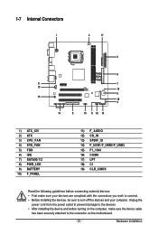
...) CD_IN 13) SPDIF_IO 14) F_USB1/F_USB2/F_USB3 15) F1_1394 16) COMA 17) LPT 18) CI 19) CLR_CMOS Read the following guidelines before turning on the motherboard. - 23 - Hardware Installation Unplug the power cord from the power outlet to prevent damage to the devices. • After installing the device and before connecting...
...) CD_IN 13) SPDIF_IO 14) F_USB1/F_USB2/F_USB3 15) F1_1394 16) COMA 17) LPT 18) CI 19) CLR_CMOS Read the following guidelines before turning on the motherboard. - 23 - Hardware Installation Unplug the power cord from the power outlet to prevent damage to the devices. • After installing the device and before connecting...
Manual
Page 24
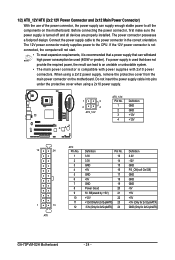
... into pins under the protective cover when using a 2x12 power supply, remove the protective cover from the main power connector on the motherboard. The 12V power connector mainly supplies power to the power connector in the correct orientation. Before connecting the power connector, first make ...3.3V -12V GND PS_ON(soft On/Off) GND GND GND -5V +5V +5V +5V (Only for 2x12-pinATX) GND (Only for 2x12-pinATX) GA-73PVM-S2H Motherboard - 24 - Connect the power supply cable to the CPU. The power connector possesses a foolproof design. If a power supply is compatible with power supplies...
... into pins under the protective cover when using a 2x12 power supply, remove the protective cover from the main power connector on the motherboard. The 12V power connector mainly supplies power to the power connector in the correct orientation. Before connecting the power connector, first make ...3.3V -12V GND PS_ON(soft On/Off) GND GND GND -5V +5V +5V +5V (Only for 2x12-pinATX) GND (Only for 2x12-pinATX) GA-73PVM-S2H Motherboard - 24 - Connect the power supply cable to the CPU. The power connector possesses a foolproof design. If a power supply is compatible with power supplies...


