
Manual
Page 2
... Summary 5 1.2 GA-5YASV-RH Motherboard Components 8 Chapter 2 Hardware Installation Process 10 2-1: Installing Processor and CPU Haet Sink 10 2-1-1: Installing CPU ...10 2-1-2: Installing Cooling Fan 11 2-2: Install Memory Modules 12 2-3: Connect ribbon cables, cabinet wires, and power supply 14 2-3-1 : I/O Back Panel Introduction 14 2-4: Connectors Introduction 16 2-5: Jumper Setting 24 2-6: Block Diagram 33 Chapter 3 BIOS Setup...
... Summary 5 1.2 GA-5YASV-RH Motherboard Components 8 Chapter 2 Hardware Installation Process 10 2-1: Installing Processor and CPU Haet Sink 10 2-1-1: Installing CPU ...10 2-1-2: Installing Cooling Fan 11 2-2: Install Memory Modules 12 2-3: Connect ribbon cables, cabinet wires, and power supply 14 2-3-1 : I/O Back Panel Introduction 14 2-4: Connectors Introduction 16 2-5: Jumper Setting 24 2-6: Block Diagram 33 Chapter 3 BIOS Setup...

Manual
Page 3
English Table of Content Chapter 4 INTEL RAID BIOS Configuration 67 Chapter 5 Appendix 72 3
English Table of Content Chapter 4 INTEL RAID BIOS Configuration 67 Chapter 5 Appendix 72 3

Manual
Page 6
English GA-5YASV-RH Motherboard Hardware Monitor On-Board LAN BIOS Special Features Additional Features Enhanced features with CPU Vcore, 1.2V reference, VCC3 (3.3V) , VBAT3V, +5VSB, CPU Temperature, and System Temperature Values viewing CPU/Power/System... Revolution Detect CPU shutdown when overheat System Voltage Detect Intel® 82566DM & 82573LGbE controllers Supports dual Gigabit LAN ports I/O Acceleration Technology Supports WOL Phoenix BIOS on 8Mb flash ROM Ehanced feature with GSMT Lite Utility PS/2 Mouse wake up from S1 under Windows Operating System External Modem wake up Supports...
English GA-5YASV-RH Motherboard Hardware Monitor On-Board LAN BIOS Special Features Additional Features Enhanced features with CPU Vcore, 1.2V reference, VCC3 (3.3V) , VBAT3V, +5VSB, CPU Temperature, and System Temperature Values viewing CPU/Power/System... Revolution Detect CPU shutdown when overheat System Voltage Detect Intel® 82566DM & 82573LGbE controllers Supports dual Gigabit LAN ports I/O Acceleration Technology Supports WOL Phoenix BIOS on 8Mb flash ROM Ehanced feature with GSMT Lite Utility PS/2 Mouse wake up from S1 under Windows Operating System External Modem wake up Supports...

Manual
Page 12
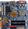
GA-5YASV-RH has 4 dual inline memory module (DIMM) sokcets. The BIOS will automatically detects memory type and size during system boot. It supports Dual Channels Technology. Channel B 12 Channel A For detail DIMM installation, please refer to the following instructions. English GA-5YASV-RH Motherboard 2-2: Install Memory Modules Before installing the processor and heatsink, adhere to the following warning: When DIMM LED is ON, do not install/remove DIMM from socket.
GA-5YASV-RH has 4 dual inline memory module (DIMM) sokcets. The BIOS will automatically detects memory type and size during system boot. It supports Dual Channels Technology. Channel B 12 Channel A For detail DIMM installation, please refer to the following instructions. English GA-5YASV-RH Motherboard 2-2: Install Memory Modules Before installing the processor and heatsink, adhere to the following warning: When DIMM LED is ON, do not install/remove DIMM from socket.

Manual
Page 31
GA-5YASV-RH Motherboard 9 ) RECCOVERY1 ( BIOS recovery jumper) English 1 1-2 Close: Enable BIOS Recovery function. 1 2-3 Close: Normal (Default setting) 31
GA-5YASV-RH Motherboard 9 ) RECCOVERY1 ( BIOS recovery jumper) English 1 1-2 Close: Enable BIOS Recovery function. 1 2-3 Close: Normal (Default setting) 31

Manual
Page 32
English GA-5YASV-RH Motherboard 10 ) PASSWORD1 (Skip password jumper) 1 1-2 Close: Skip Supervisor Password in BIOS setup menu 1 2-3 Close: Normal (Default setting) 32
English GA-5YASV-RH Motherboard 10 ) PASSWORD1 (Skip password jumper) 1 1-2 Close: Skip Supervisor Password in BIOS setup menu 1 2-3 Close: Normal (Default setting) 32

Manual
Page 34
GA-5YASV-RH Motherboard Chapter 3 BIOS Setup BIOS Setup is an overview of information is stored in the right hand Main Menu - This type of the BIOS Setup Program. Exit current page and return to enter Setup. CONTROL KEYS Move to previous item Move to next item Move to the item in ...
GA-5YASV-RH Motherboard Chapter 3 BIOS Setup BIOS Setup is an overview of information is stored in the right hand Main Menu - This type of the BIOS Setup Program. Exit current page and return to enter Setup. CONTROL KEYS Move to previous item Move to next item Move to the item in ...
Manual
Page 35
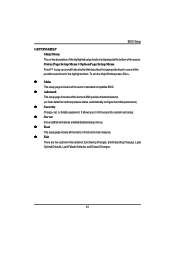
z Advanced This setup page includes all the items of first boot function features. BIOS Setup GETTINGHELP Main Menu The on-line description of the highlighted setup function is displayed at the bottom of AMI special enhanced features. (ex: Auto .... To exit the Help Window press . z Server Server additional features enabled/disabled setup menus. z Main This setup page includes all the items in standard compatible BIOS.
z Advanced This setup page includes all the items of first boot function features. BIOS Setup GETTINGHELP Main Menu The on-line description of the highlighted setup function is displayed at the bottom of AMI special enhanced features. (ex: Auto .... To exit the Help Window press . z Server Server additional features enabled/disabled setup menus. z Main This setup page includes all the items in standard compatible BIOS.

Manual
Page 36
Figure 1: Main System Time The time is calculated based on the screen. GA-5YASV-RH Motherboard Main Once you set the date. (Weekend: DD: MM: YY) (YY: 1099~2099) 36 Set the System Time (HH:MM:SS) System Date Set the System Date. Note that the "Day" automatically changed after you enter Phoenix BIOS Setup Utility, the Main Menu (Figure 1) will appear on the 24-hour military time clock. Use arrow keys to select among the items and press to accept or enter the sub-menu.
Figure 1: Main System Time The time is calculated based on the screen. GA-5YASV-RH Motherboard Main Once you set the date. (Weekend: DD: MM: YY) (YY: 1099~2099) 36 Set the System Time (HH:MM:SS) System Date Set the System Date. Note that the "Day" automatically changed after you enter Phoenix BIOS Setup Utility, the Main Menu (Figure 1) will appear on the 24-hour military time clock. Use arrow keys to select among the items and press to accept or enter the sub-menu.

Manual
Page 37
... are two types: auto type, and manual type. Note that has been installed in the documentation form your drive must match with the drive table. BIOS Setup Legacy Diskette A This category identifies the type of your hard disk vendor or the system manufacturer. 37 Auto type which will be provided in...
... are two types: auto type, and manual type. Note that has been installed in the documentation form your drive must match with the drive table. BIOS Setup Legacy Diskette A This category identifies the type of your hard disk vendor or the system manufacturer. 37 Auto type which will be provided in...

Manual
Page 39
... and VID. Setup menu for C1 Enhanced Mode, No Execute Mode Memory Protection, Intel EIST Support, Intel Virtualization Technology, and PECI Interface. Advanced Processor Options BIOS Setup Figure 1-1: Advanced Processor Option Advanced Processor Option This category includes the information of CPU Speed, Processor CPUID, and Processor L2 Cache.
... and VID. Setup menu for C1 Enhanced Mode, No Execute Mode Memory Protection, Intel EIST Support, Intel Virtualization Technology, and PECI Interface. Advanced Processor Options BIOS Setup Figure 1-1: Advanced Processor Option Advanced Processor Option This category includes the information of CPU Speed, Processor CPUID, and Processor L2 Cache.

Manual
Page 41
User can change the processor options, chipset configuration, PCI configuration and chipset control. Figure 2: Advanced 41 Advanced BIOS Setup About This Section: Advanced With this section, allowing user to configure your system for basic operation.
User can change the processor options, chipset configuration, PCI configuration and chipset control. Figure 2: Advanced 41 Advanced BIOS Setup About This Section: Advanced With this section, allowing user to configure your system for basic operation.

Manual
Page 42
.../ DIMM Group 1,2,3,4 Status These category is display-only which is determined by POST (Power On Self Test) of the BIOS. Save the changes and restart system. Disable this function. (Default setting) 42 GA-5YASV-RH Motherboard Memory Configuration Figure 2-1: Memory Configuration Installed Memory/Available to 'No' automatically. After rebooting system, the Memory Reset item...
.../ DIMM Group 1,2,3,4 Status These category is display-only which is determined by POST (Power On Self Test) of the BIOS. Save the changes and restart system. Disable this function. (Default setting) 42 GA-5YASV-RH Motherboard Memory Configuration Figure 2-1: Memory Configuration Installed Memory/Available to 'No' automatically. After rebooting system, the Memory Reset item...

Manual
Page 43
LAN1 Option ROM Scan Enabled Enableing this item to initialize device expansion ROM. (Defualt setting) Disabled Disable this function. PCI Configuration BIOS Setup Figure 2-2: PCI Configuration Embedded NIC Onboard LAN1 Control Enabled Enable onboard LAN device. (Default setting) Disabled Disable this function. 43
LAN1 Option ROM Scan Enabled Enableing this item to initialize device expansion ROM. (Defualt setting) Disabled Disable this function. PCI Configuration BIOS Setup Figure 2-2: PCI Configuration Embedded NIC Onboard LAN1 Control Enabled Enable onboard LAN device. (Default setting) Disabled Disable this function. 43

Manual
Page 47
... LPC bus. 47 Set Interrupt as Enhanced Parallel Port. Enabled Enable USB controller. (Default setting) Disabled Disbale this setting to either PCI or LPC bus. BIOS Setup Bi-directional Use this function. PCI Set Route Port 80h I/O cycles to the PCI bus. (Default setting) LPC Set Route Port 80h I /O Address 378...
... LPC bus. 47 Set Interrupt as Enhanced Parallel Port. Enabled Enable USB controller. (Default setting) Disabled Disbale this setting to either PCI or LPC bus. BIOS Setup Bi-directional Use this function. PCI Set Route Port 80h I/O cycles to the PCI bus. (Default setting) LPC Set Route Port 80h I /O Address 378...

Manual
Page 49
Enabled Enable Wake On LAN/PME. (Default setting) Disabled Disable this function. (Default setting) Wake On LAN / PME This option allow user to determine the action of the system when a LAN/PME wake up event occurs. Disabled Disable this function. Note: This item must enabled if you're running under Windows operating system. 49 Advanced Chipset Control BIOS Setup Figure 2-4: Advanced Chipset Control Enable Multimedia Timer Enabled Enable Multimedia Timer support.
Enabled Enable Wake On LAN/PME. (Default setting) Disabled Disable this function. (Default setting) Wake On LAN / PME This option allow user to determine the action of the system when a LAN/PME wake up event occurs. Disabled Disable this function. Note: This item must enabled if you're running under Windows operating system. 49 Advanced Chipset Control BIOS Setup Figure 2-4: Advanced Chipset Control Enable Multimedia Timer Enabled Enable Multimedia Timer support.

Manual
Page 51
FAN Monitor: CPU Fan/ System Fan/ Front Fan/ Rear Fan (RPM) Display the current CPU and system fAN speed. 51 Voltage Monitor: DDR1V8, VCC3V3, VCORE, 12V2, 5V Detect system's voltage status automatically. Hardware Monitor BIOS Setup Figure 2-5: Hardware Monitor CPU / Motherboard/ DDR Temperature Display the current CPU temperature, Motherboard, and Ambient temperature.
FAN Monitor: CPU Fan/ System Fan/ Front Fan/ Rear Fan (RPM) Display the current CPU and system fAN speed. 51 Voltage Monitor: DDR1V8, VCC3V3, VCORE, 12V2, 5V Detect system's voltage status automatically. Hardware Monitor BIOS Setup Figure 2-5: Hardware Monitor CPU / Motherboard/ DDR Temperature Display the current CPU temperature, Motherboard, and Ambient temperature.

Manual
Page 53
... . You may also press to 6 characters in creating a password. In addition, user also can set the virus protection for different level of password securities. Security BIOS Setup * About This Section: Security In this function, the following message will appear at the center of the setup menus. You will clear any previously...
... . You may also press to 6 characters in creating a password. In addition, user also can set the virus protection for different level of password securities. Security BIOS Setup * About This Section: Security In this function, the following message will appear at the center of the setup menus. You will clear any previously...

Manual
Page 56
Including information of BIOS Version. GA-5YASV-RH Motherboard System Management Figure 4-1: System Management Server Management This category allows user to view the server management features. All items in this menu cannot be modified in user's mode. If any items require changes, please consult your system supervisor. 56
Including information of BIOS Version. GA-5YASV-RH Motherboard System Management Figure 4-1: System Management Server Management This category allows user to view the server management features. All items in this menu cannot be modified in user's mode. If any items require changes, please consult your system supervisor. 56

Manual
Page 57
Serial Port A Use Serial Port as he COMA port address. Serial Port B Use Serial Port as he COMB port address. Disabled Disable this option is set to set the specified baud rate. Baud Rate This option allows user to enabled, it will use a port on the motherboard. Options 300, 1200, 2400, 9600, 19.2K, 38.4K, 57.6K, 115.2K. 57 Console Redirection BIOS Setup Figure 4-2: Console Redirection BIOS Redirection Port If this function. (Default setting) Note: Tower has COMA and COMB.
Serial Port A Use Serial Port as he COMA port address. Serial Port B Use Serial Port as he COMB port address. Disabled Disable this option is set to set the specified baud rate. Baud Rate This option allows user to enabled, it will use a port on the motherboard. Options 300, 1200, 2400, 9600, 19.2K, 38.4K, 57.6K, 115.2K. 57 Console Redirection BIOS Setup Figure 4-2: Console Redirection BIOS Redirection Port If this function. (Default setting) Note: Tower has COMA and COMB.


