Manual
Page 1
G1.Sniper LGA1366 socket motherboard for Intel® Core™ i7 processor family User's Manual Rev. 1001 12ME-G1SNIPE-1001R
G1.Sniper LGA1366 socket motherboard for Intel® Core™ i7 processor family User's Manual Rev. 1001 12ME-G1SNIPE-1001R

Manual
Page 2
Motherboard G1.Sniper Feb. 1, 2011 Motherboard G1.Sniper Feb. 1, 2011
Motherboard G1.Sniper Feb. 1, 2011 Motherboard G1.Sniper Feb. 1, 2011

Manual
Page 3
For product-related information, check on our website at: http://www.gigabyte.com Identifying Your Motherboard Revision The revision number on your motherboard revision before updating motherboard BIOS, drivers, or when looking for technical information. Check your motherboard looks like this product, GIGABYTE provides the following types of documentations: For quick set-up of this : "REV...
For product-related information, check on our website at: http://www.gigabyte.com Identifying Your Motherboard Revision The revision number on your motherboard revision before updating motherboard BIOS, drivers, or when looking for technical information. Check your motherboard looks like this product, GIGABYTE provides the following types of documentations: For quick set-up of this : "REV...
Manual
Page 4
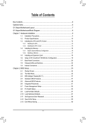
Table of Contents Box Contents...6 Optional Items...6 G1.Sniper Motherboard Layout 7 G1.Sniper Motherboard Block Diagram 8 Chapter 1 Hardware Installation 9 1-1 Installation Precautions 9 1-2 Product Specifications 10 1-3 Installing the CPU and CPU Cooler 13 1-3-1 Installing the CPU 13 1-3-2 Installing the CPU Cooler ...
Table of Contents Box Contents...6 Optional Items...6 G1.Sniper Motherboard Layout 7 G1.Sniper Motherboard Block Diagram 8 Chapter 1 Hardware Installation 9 1-1 Installation Precautions 9 1-2 Product Specifications 10 1-3 Installing the CPU and CPU Cooler 13 1-3-1 Installing the CPU 13 1-3-2 Installing the CPU Cooler ...
Manual
Page 6
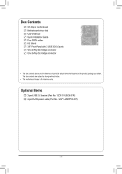
Box Contents G1.Sniper motherboard Motherboard driver disk User's Manual Quick Installation Guide Four SATA cables I/O Shield 3.5" Front Panel with 2 USB 3.0/2.0 ports One 2-Way SLI bridge connector One 3-Way SLI bridge connector • The box contents above are subject to change without notice. • The motherboard image is for reference only and the actual items shall depend on the product package you obtain. The box contents are for reference only. Optional Items 2-port USB 2.0 bracket (Part No. 12CR1-1UB030-5*R) 2-port SATA power cable (Part No. 12CF1-2SERPW-0*R) - 6 -
Box Contents G1.Sniper motherboard Motherboard driver disk User's Manual Quick Installation Guide Four SATA cables I/O Shield 3.5" Front Panel with 2 USB 3.0/2.0 ports One 2-Way SLI bridge connector One 3-Way SLI bridge connector • The box contents above are subject to change without notice. • The motherboard image is for reference only and the actual items shall depend on the product package you obtain. The box contents are for reference only. Optional Items 2-port USB 2.0 bracket (Part No. 12CR1-1UB030-5*R) 2-port SATA power cable (Part No. 12CF1-2SERPW-0*R) - 6 -
Manual
Page 7
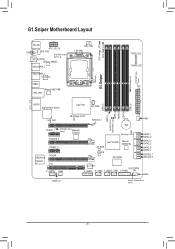
G1.Sniper Motherboard Layout CPU Voltage L1/2/3 CPU TEMP L1/2 KB_MS ATX_12V_2X COAXIAL SYS_FAN SYSTEM2 Temp. LED PHASE LED ATX DDR3_2 DDR3_1 NB PHASE LED DDR PHASE LED ...; X58 HP_PWR LAN_LED NB Voltage L1/2/3 PCIEX16_1 PCIEX1_1 SYSTEM1 sensor Temp. sensor OC_BUTTON JMicron JMB362 USB_ESATA_2 USB_ESATA_1 VLI VL810 USB30 Marvell 88E1118R USB_LAN CPU_FAN LGA1366 G1.Sniper DDR Voltage LED SYSTEM3 Temp. Renesas D720200 BAT SB Voltage L1/2/3 PCIEX16_2 PCIEX1_2 Intel® ICH10R M_BIOS Marvell 88SE9182 CREATIVE CA20K2 PCIEX8 PCI F_AUDIO FAN1...
G1.Sniper Motherboard Layout CPU Voltage L1/2/3 CPU TEMP L1/2 KB_MS ATX_12V_2X COAXIAL SYS_FAN SYSTEM2 Temp. LED PHASE LED ATX DDR3_2 DDR3_1 NB PHASE LED DDR PHASE LED ...; X58 HP_PWR LAN_LED NB Voltage L1/2/3 PCIEX16_1 PCIEX1_1 SYSTEM1 sensor Temp. sensor OC_BUTTON JMicron JMB362 USB_ESATA_2 USB_ESATA_1 VLI VL810 USB30 Marvell 88E1118R USB_LAN CPU_FAN LGA1366 G1.Sniper DDR Voltage LED SYSTEM3 Temp. Renesas D720200 BAT SB Voltage L1/2/3 PCIEX16_2 PCIEX1_2 Intel® ICH10R M_BIOS Marvell 88SE9182 CREATIVE CA20K2 PCIEX8 PCI F_AUDIO FAN1...
Manual
Page 8
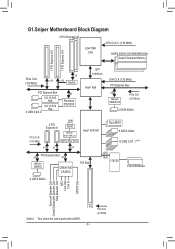
G1.Sniper Motherboard Block Diagram 2 PCI Express x8 LGA1366 CPU CPU CLK+/- (133 MHz) DDR3 2200/1333/1066/800 MHz Dual/3 Channel Memory 1 PCI Express x16 1 PCI Express ...
G1.Sniper Motherboard Block Diagram 2 PCI Express x8 LGA1366 CPU CPU CLK+/- (133 MHz) DDR3 2200/1333/1066/800 MHz Dual/3 Channel Memory 1 PCI Express x16 1 PCI Express ...
Manual
Page 9
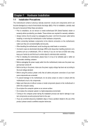
...computer system in a high-temperature environment. • Turning on top of your dealer. Chapter 1 Hardware Installation 1-1 Installation Precautions The motherboard contains numerous delicate electronic circuits and components which can lead to damage to system components as well as physical harm to the user. ...• If you are connected tightly and securely. • When handling the motherboard, avoid touching any installation steps or have a problem related to the use of the product, please consult a certified computer technician. -...
...computer system in a high-temperature environment. • Turning on top of your dealer. Chapter 1 Hardware Installation 1-1 Installation Precautions The motherboard contains numerous delicate electronic circuits and components which can lead to damage to system components as well as physical harm to the user. ...• If you are connected tightly and securely. • When handling the motherboard, avoid touching any installation steps or have a problem related to the use of the product, please consult a certified computer technician. -...

Manual
Page 12
...138;Š Support for Xpress Install ŠŠ Support for Xpress Recovery2 ŠŠ Support for EasyTune * Available functions in EasyTune may differ by motherboard model. ŠŠ Support for Dynamic Energy Saver™ 2 ŠŠ Support for Smart 6™ ŠŠ Support for Auto Green...;Š Support for Microsoft® Windows 7/Vista/XP Form Factor ŠŠ ATX Form Factor; 30.5cm x 26.4cm * GIGABYTE reserves the right to make any changes to the product specifications and product-related information without prior notice. Hardware Installation - 12 -
...138;Š Support for Xpress Install ŠŠ Support for Xpress Recovery2 ŠŠ Support for EasyTune * Available functions in EasyTune may differ by motherboard model. ŠŠ Support for Dynamic Energy Saver™ 2 ŠŠ Support for Smart 6™ ŠŠ Support for Auto Green...;Š Support for Microsoft® Windows 7/Vista/XP Form Factor ŠŠ ATX Form Factor; 30.5cm x 26.4cm * GIGABYTE reserves the right to make any changes to the product specifications and product-related information without prior notice. Hardware Installation - 12 -

Manual
Page 13
...8226; Apply an even and thin layer of thermal grease on the computer if the CPU cooler is not recommended that the motherboard supports the CPU. (Go to GIGABYTE's website for the peripherals. It is not installed, otherwise overheating and dam- Hardware Installation The CPU cannot be set the...to your hardware specifications including the CPU, graphics card, memory, hard drive, etc. 1-3-1 Installing the CPU A. Locate the alignment keys on the motherboard CPU socket and the notches on the CPU Notch Notch - 13 - If you wish to set beyond the standard specifications, please do so ...
...8226; Apply an even and thin layer of thermal grease on the computer if the CPU cooler is not recommended that the motherboard supports the CPU. (Go to GIGABYTE's website for the peripherals. It is not installed, otherwise overheating and dam- Hardware Installation The CPU cannot be set the...to your hardware specifications including the CPU, graphics card, memory, hard drive, etc. 1-3-1 Installing the CPU A. Locate the alignment keys on the motherboard CPU socket and the notches on the CPU Notch Notch - 13 - If you wish to set beyond the standard specifications, please do so ...

Manual
Page 14
.... Step 3: Use your finger. Step 2: Lift the metal load plate from the socket with the socket alignment keys) and gently insert the CPU into the motherboard CPU socket. Before installing the CPU, make sure to turn off the computer and unplug the power cord from the power outlet to prevent damage...
.... Step 3: Use your finger. Step 2: Lift the metal load plate from the socket with the socket alignment keys) and gently insert the CPU into the motherboard CPU socket. Before installing the CPU, make sure to turn off the computer and unplug the power cord from the power outlet to prevent damage...

Manual
Page 15
... If the push pin is inserted as the example cooler.) Step 1: Apply an even and thin layer of thermal grease on the surface of the motherboard. Step 6: Finally, attach the power connector of the CPU cooler to the CPU fan header (CPU_FAN) on installing the cooler.) Step 5: After ...click" when pushing down on the push pins diagonally. 1-3-2 Installing the CPU Cooler Follow the steps below to correctly install the CPU cooler on the motherboard. (The following procedure uses Intel® boxed cooler as the picture above shows, the installation is to install.) Step 3: Place the cooler atop ...
... If the push pin is inserted as the example cooler.) Step 1: Apply an even and thin layer of thermal grease on the surface of the motherboard. Step 6: Finally, attach the power connector of the CPU cooler to the CPU fan header (CPU_FAN) on installing the cooler.) Step 5: After ...click" when pushing down on the push pins diagonally. 1-3-2 Installing the CPU Cooler Follow the steps below to correctly install the CPU cooler on the motherboard. (The following procedure uses Intel® boxed cooler as the picture above shows, the installation is to install.) Step 3: Place the cooler atop ...

Manual
Page 16
...you begin to install the memory: • Make sure that memory of the same capacity, brand, speed, and chips be used. (Go to GIGABYTE's website for the latest supported memory speeds and momery moudles.) • Always turn off the computer and unplug the power cord from the power ...or 3 Channel mode. DS/SS - - DDR3_2 DDR3_1 DDR3_4 DDR3_3 DDR3_6 DDR3_5 Due to install them in only one DDR3 memory module is recommended that the motherboard supports the memory. A memory module can be installed in the DDR3_1, DDR3_3 and DDR3_5 sockets. DS/SS - - The six DDR3 memory sockets are ...
...you begin to install the memory: • Make sure that memory of the same capacity, brand, speed, and chips be used. (Go to GIGABYTE's website for the latest supported memory speeds and momery moudles.) • Always turn off the computer and unplug the power cord from the power ...or 3 Channel mode. DS/SS - - DDR3_2 DDR3_1 DDR3_4 DDR3_3 DDR3_6 DDR3_5 Due to install them in only one DDR3 memory module is recommended that the motherboard supports the memory. A memory module can be installed in the DDR3_1, DDR3_3 and DDR3_5 sockets. DS/SS - - The six DDR3 memory sockets are ...

Manual
Page 17
..., make sure to turn off the computer and unplug the power cord from the power outlet to prevent damage to install DDR3 DIMMs on this motherboard. Follow the steps below to correctly install your fingers on the top edge of the socket will snap into the memory socket. Spread the retaining...
..., make sure to turn off the computer and unplug the power cord from the power outlet to prevent damage to install DDR3 DIMMs on this motherboard. Follow the steps below to correctly install your fingers on the top edge of the socket will snap into the memory socket. Spread the retaining...
Manual
Page 18
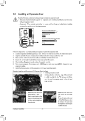
...) PCI Express x1 Slot PCI Express x16 Slot (PCIEX16_2/PCIEX8) PCI Slot Follow the steps below to install an expansion card: • Make sure the motherboard supports the expansion card.
...) PCI Express x1 Slot PCI Express x16 Slot (PCIEX16_2/PCIEX8) PCI Slot Follow the steps below to install an expansion card: • Make sure the motherboard supports the expansion card.
Manual
Page 19
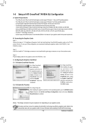
... Card Driver C-1. For 2-Way/3-Way SLI: After installing the graphics card driver in the operating system, go to the Catalyst Control Center. A CrossFireX/SLI-supported motherboard with sufficient power is enabled. (Note) The bridge connectors may be needed or not depending on your graphics cards for enabling CrossFireX/SLI technology may...
... Card Driver C-1. For 2-Way/3-Way SLI: After installing the graphics card driver in the operating system, go to the Catalyst Control Center. A CrossFireX/SLI-supported motherboard with sufficient power is enabled. (Note) The bridge connectors may be needed or not depending on your graphics cards for enabling CrossFireX/SLI technology may...
Manual
Page 20
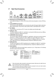
... Port The Gigabit Ethernet LAN port provides Internet connection at up to an external audio system that your device and then remove it from the motherboard. • When removing the cable, pull it side to side to Chapter 5, "Configuring SATA Hard Drive(s)," for USB devices such as a USB keyboard/mouse, USB...
... Port The Gigabit Ethernet LAN port provides Internet connection at up to an external audio system that your device and then remove it from the motherboard. • When removing the cable, pull it side to side to Chapter 5, "Configuring SATA Hard Drive(s)," for USB devices such as a USB keyboard/mouse, USB...
Manual
Page 22
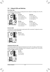
... LEDs. CPU TEMP Off: Below 60oC L1: 61~ 80oC (green) L2: Over 80oC (red) Hardware Installation - 22 - FREQ. 1-8 Onboard LEDs and Switches Overvoltage LEDs This motherboard contains 4 sets of overvoltage LEDs which level the CPU is below 60oC;
... LEDs. CPU TEMP Off: Below 60oC L1: 61~ 80oC (green) L2: Over 80oC (red) Hardware Installation - 22 - FREQ. 1-8 Onboard LEDs and Switches Overvoltage LEDs This motherboard contains 4 sets of overvoltage LEDs which level the CPU is below 60oC;

Manual
Page 25
..., make sure your devices are compliant with the connectors you wish to connect. • Before installing the devices, be sure to the connector on the motherboard. - 25 - Hardware Installation Unplug the power cord from the power outlet to prevent damage to the devices. • After installing the device and before connecting...
..., make sure your devices are compliant with the connectors you wish to connect. • Before installing the devices, be sure to the connector on the motherboard. - 25 - Hardware Installation Unplug the power cord from the power outlet to prevent damage to the devices. • After installing the device and before connecting...
Manual
Page 26
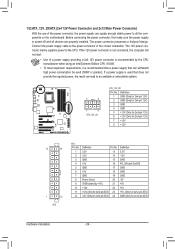
... power connector mainly supplies power to the power connector in the correct orientation. If a power supply is turned off and all the components on the motherboard. Definition 1 GND (Only for 2x4-pin 12V) 2 GND (Only for 2x4-pin 12V) 3 GND 4 GND 5 +12V (Only for 2x4-pin 12V) 6 +12V (Only for 2x12...
... power connector mainly supplies power to the power connector in the correct orientation. If a power supply is turned off and all the components on the motherboard. Definition 1 GND (Only for 2x4-pin 12V) 2 GND (Only for 2x4-pin 12V) 3 GND 4 GND 5 +12V (Only for 2x4-pin 12V) 6 +12V (Only for 2x12...


