
Manual
Page 1
G1.Sniper LGA1366 socket motherboard for Intel® Core™ i7 processor family User's Manual Rev. 1001 12ME-G1SNIPE-1001R
G1.Sniper LGA1366 socket motherboard for Intel® Core™ i7 processor family User's Manual Rev. 1001 12ME-G1SNIPE-1001R

Manual
Page 2
Motherboard G1.Sniper Feb. 1, 2011 Motherboard G1.Sniper Feb. 1, 2011
Motherboard G1.Sniper Feb. 1, 2011 Motherboard G1.Sniper Feb. 1, 2011

Manual
Page 3
... be reproduced, copied, translated, transmitted, or published in this : "REV: X.X." No part of GIGABYTE. For product-related information, check on our website at: http://www.gigabyte.com Identifying Your Motherboard Revision The revision number on your motherboard revision before updating motherboard BIOS, drivers, or when looking for technical information. Example: For example, "REV: 1.0" means the...
... be reproduced, copied, translated, transmitted, or published in this : "REV: X.X." No part of GIGABYTE. For product-related information, check on our website at: http://www.gigabyte.com Identifying Your Motherboard Revision The revision number on your motherboard revision before updating motherboard BIOS, drivers, or when looking for technical information. Example: For example, "REV: 1.0" means the...
Manual
Page 4
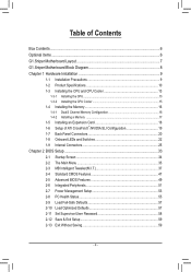
Table of Contents Box Contents...6 Optional Items...6 G1.Sniper Motherboard Layout 7 G1.Sniper Motherboard Block Diagram 8 Chapter 1 Hardware Installation 9 1-1 Installation Precautions 9 1-2 Product Specifications 10 1-3 Installing the CPU and CPU Cooler 13 1-3-1 Installing the CPU 13 1-3-2 Installing the CPU Cooler ...
Table of Contents Box Contents...6 Optional Items...6 G1.Sniper Motherboard Layout 7 G1.Sniper Motherboard Block Diagram 8 Chapter 1 Hardware Installation 9 1-1 Installation Precautions 9 1-2 Product Specifications 10 1-3 Installing the CPU and CPU Cooler 13 1-3-1 Installing the CPU 13 1-3-2 Installing the CPU Cooler ...
Manual
Page 6
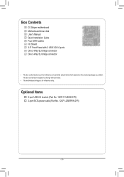
Box Contents G1.Sniper motherboard Motherboard driver disk User's Manual Quick Installation Guide Four SATA cables I/O Shield 3.5" Front Panel with 2 USB 3.0/2.0 ports One 2-Way SLI bridge connector One 3-Way SLI bridge connector • The box contents above are subject to change without notice. • The motherboard image is for reference only and the actual items shall depend on the product package you obtain. Optional Items 2-port USB 2.0 bracket (Part No. 12CR1-1UB030-5*R) 2-port SATA power cable (Part No. 12CF1-2SERPW-0*R) - 6 - The box contents are for reference only.
Box Contents G1.Sniper motherboard Motherboard driver disk User's Manual Quick Installation Guide Four SATA cables I/O Shield 3.5" Front Panel with 2 USB 3.0/2.0 ports One 2-Way SLI bridge connector One 3-Way SLI bridge connector • The box contents above are subject to change without notice. • The motherboard image is for reference only and the actual items shall depend on the product package you obtain. Optional Items 2-port USB 2.0 bracket (Part No. 12CR1-1UB030-5*R) 2-port SATA power cable (Part No. 12CF1-2SERPW-0*R) - 6 - The box contents are for reference only.
Manual
Page 7
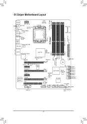
... DDR PHASE LED DDR3_4 DDR3_3 DDR3_6 DDR3_5 AUDIO BigFoot Killer E2100 Intel® X58 HP_PWR LAN_LED NB Voltage L1/2/3 PCIEX16_1 PCIEX1_1 SYSTEM1 sensor Temp. G1.Sniper Motherboard Layout CPU Voltage L1/2/3 CPU TEMP L1/2 KB_MS ATX_12V_2X COAXIAL SYS_FAN SYSTEM2 Temp. sensor FREQ. Renesas D720200 BAT SB Voltage L1/2/3 PCIEX16_2 PCIEX1_2... SATA2_4 GSATA3_7 GSATA3_6 FAN2 SPDIF_O System Temperature sensor - 7 - sensor OC_BUTTON JMicron JMB362 USB_ESATA_2 USB_ESATA_1 VLI VL810 USB30 Marvell 88E1118R USB_LAN CPU_FAN LGA1366 G1.Sniper DDR Voltage LED SYSTEM3 Temp.
... DDR PHASE LED DDR3_4 DDR3_3 DDR3_6 DDR3_5 AUDIO BigFoot Killer E2100 Intel® X58 HP_PWR LAN_LED NB Voltage L1/2/3 PCIEX16_1 PCIEX1_1 SYSTEM1 sensor Temp. G1.Sniper Motherboard Layout CPU Voltage L1/2/3 CPU TEMP L1/2 KB_MS ATX_12V_2X COAXIAL SYS_FAN SYSTEM2 Temp. sensor FREQ. Renesas D720200 BAT SB Voltage L1/2/3 PCIEX16_2 PCIEX1_2... SATA2_4 GSATA3_7 GSATA3_6 FAN2 SPDIF_O System Temperature sensor - 7 - sensor OC_BUTTON JMicron JMB362 USB_ESATA_2 USB_ESATA_1 VLI VL810 USB30 Marvell 88E1118R USB_LAN CPU_FAN LGA1366 G1.Sniper DDR Voltage LED SYSTEM3 Temp.
Manual
Page 8
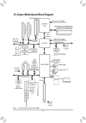
G1.Sniper Motherboard Block Diagram 2 PCI Express x8 LGA1366 CPU CPU CLK+/- (133 MHz) DDR3 2200/1333/1066/800 MHz Dual/3 Channel Memory 1 PCI Express x16 1 PCI Express ...
G1.Sniper Motherboard Block Diagram 2 PCI Express x8 LGA1366 CPU CPU CLK+/- (133 MHz) DDR3 2200/1333/1066/800 MHz Dual/3 Channel Memory 1 PCI Express x16 1 PCI Express ...
Manual
Page 9
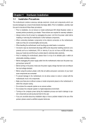
... damage to system components as well as physical harm to the user. • If you are connected tightly and securely. • When handling the motherboard, avoid touching any metal leads or connectors. • It is best to wear an electrostatic discharge (ESD) wrist strap when handling electronic com- Prior... or have it on top of an antistatic pad or within an electrostatic shielding container. • Before unplugging the power supply cable from the motherboard, make sure the power supply has been turned off. • Before turning on the power, make sure the power supply voltage has been ...
... damage to system components as well as physical harm to the user. • If you are connected tightly and securely. • When handling the motherboard, avoid touching any metal leads or connectors. • It is best to wear an electrostatic discharge (ESD) wrist strap when handling electronic com- Prior... or have it on top of an antistatic pad or within an electrostatic shielding container. • Before unplugging the power supply cable from the motherboard, make sure the power supply has been turned off. • Before turning on the power, make sure the power supply voltage has been ...

Manual
Page 12
...138;Š Support for Xpress Install ŠŠ Support for Xpress Recovery2 ŠŠ Support for EasyTune * Available functions in EasyTune may differ by motherboard model. ŠŠ Support for Dynamic Energy Saver™ 2 ŠŠ Support for Smart 6™ ŠŠ Support for Auto Green...;Š Support for Microsoft® Windows 7/Vista/XP Form Factor ŠŠ ATX Form Factor; 30.5cm x 26.4cm * GIGABYTE reserves the right to make any changes to the product specifications and product-related information without prior notice. Hardware Installation - 12 -
...138;Š Support for Xpress Install ŠŠ Support for Xpress Recovery2 ŠŠ Support for EasyTune * Available functions in EasyTune may differ by motherboard model. ŠŠ Support for Dynamic Energy Saver™ 2 ŠŠ Support for Smart 6™ ŠŠ Support for Auto Green...;Š Support for Microsoft® Windows 7/Vista/XP Form Factor ŠŠ ATX Form Factor; 30.5cm x 26.4cm * GIGABYTE reserves the right to make any changes to the product specifications and product-related information without prior notice. Hardware Installation - 12 -

Manual
Page 13
... Socket Alignment Key Alignment Key LGA1366 CPU Triangle Pin One Marking on the computer if the CPU cooler is not recommended that the motherboard supports the CPU. (Go to GIGABYTE's website for the peripherals. age of the CPU. • Do not turn off the computer and unplug the power cord from the..., graphics card, memory, hard drive, etc. 1-3-1 Installing the CPU A. It is not installed, otherwise overheating and dam- Hardware Installation Locate the alignment keys on the motherboard CPU socket and the notches on the CPU.
... Socket Alignment Key Alignment Key LGA1366 CPU Triangle Pin One Marking on the computer if the CPU cooler is not recommended that the motherboard supports the CPU. (Go to GIGABYTE's website for the peripherals. age of the CPU. • Do not turn off the computer and unplug the power cord from the..., graphics card, memory, hard drive, etc. 1-3-1 Installing the CPU A. It is not installed, otherwise overheating and dam- Hardware Installation Locate the alignment keys on the motherboard CPU socket and the notches on the CPU.

Manual
Page 14
B. Step 3: Use your thumb and index finger to correctly install the CPU into the motherboard CPU socket. Then completely lift the CPU socket lever. Step 2: Lift the metal load plate from the power outlet to prevent damage to turn off ...
B. Step 3: Use your thumb and index finger to correctly install the CPU into the motherboard CPU socket. Then completely lift the CPU socket lever. Step 2: Lift the metal load plate from the power outlet to prevent damage to turn off ...

Manual
Page 15
... CPU cooler to your CPU cooler installation manual for instructions on installing the cooler.) Step 5: After the installation, check the back of the motherboard. Hardware Installation Inadequately removing the CPU cooler may adhere to the CPU. Push down each push pin. Use extreme care when removing the CPU... installed CPU. If the push pin is inserted as the picture above shows, the installation is to correctly install the CPU cooler on the motherboard. (The following procedure uses Intel® boxed cooler as the example cooler.) Step 1: Apply an even and thin layer of thermal grease ...
... CPU cooler to your CPU cooler installation manual for instructions on installing the cooler.) Step 5: After the installation, check the back of the motherboard. Hardware Installation Inadequately removing the CPU cooler may adhere to the CPU. Push down each push pin. Use extreme care when removing the CPU... installed CPU. If the push pin is inserted as the picture above shows, the installation is to correctly install the CPU cooler on the motherboard. (The following procedure uses Intel® boxed cooler as the example cooler.) Step 1: Apply an even and thin layer of thermal grease ...

Manual
Page 16
...enabled if only one DDR3 memory module is recommended that memory of the same capacity, brand, speed, and chips be used. (Go to GIGABYTE's website for the latest supported memory speeds and momery moudles.) • Always turn off the computer and unplug the power cord from the ... and capacity of the same capacity, brand, speed, and chips be sure to insert the memory, switch the direction. 1-4-1 Dual/3 Channel Memory Configuration This motherboard provides six DDR3 memory sockets and supports Dual/3 Channel Technology. Four Modules DS/SS DS/SS DS/SS DS/SS - - - - 3 Channel Memory...
...enabled if only one DDR3 memory module is recommended that memory of the same capacity, brand, speed, and chips be used. (Go to GIGABYTE's website for the latest supported memory speeds and momery moudles.) • Always turn off the computer and unplug the power cord from the ... and capacity of the same capacity, brand, speed, and chips be sure to insert the memory, switch the direction. 1-4-1 Dual/3 Channel Memory Configuration This motherboard provides six DDR3 memory sockets and supports Dual/3 Channel Technology. Four Modules DS/SS DS/SS DS/SS DS/SS - - - - 3 Channel Memory...

Manual
Page 17
..., make sure to turn off the computer and unplug the power cord from the power outlet to prevent damage to install DDR3 DIMMs on this motherboard.
..., make sure to turn off the computer and unplug the power cord from the power outlet to prevent damage to install DDR3 DIMMs on this motherboard.
Manual
Page 18
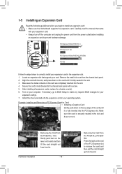
... Express slot. Remove the metal slot cover from the slot. If necessary, go to BIOS Setup to install an expansion card: • Make sure the motherboard supports the expansion card. Example: Installing and Removing a PCI Express Graphics Card: • Installing a Graphics Card: Gently push down on your card. Carefully read the...
... Express slot. Remove the metal slot cover from the slot. If necessary, go to BIOS Setup to install an expansion card: • Make sure the motherboard supports the expansion card. Example: Installing and Removing a PCI Express Graphics Card: • Installing a Graphics Card: Gently push down on your card. Carefully read the...
Manual
Page 19
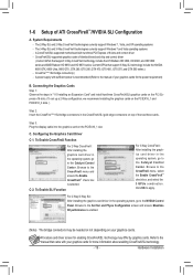
... 3800, HD 4800, and HD 5800 series and AMD Radeon HD 6950 and HD 6970 series. 1-6 Setup of the two/three cards. A CrossFireX/SLI-supported motherboard with sufficient power is recommended (Refer to the Set SLI and Physx Configuration screen and ensure Maximize 3D performance is selected. Configuring the Graphics Card...
... 3800, HD 4800, and HD 5800 series and AMD Radeon HD 6950 and HD 6970 series. 1-6 Setup of the two/three cards. A CrossFireX/SLI-supported motherboard with sufficient power is recommended (Refer to the Set SLI and Physx Configuration screen and ensure Maximize 3D performance is selected. Configuring the Graphics Card...
Manual
Page 20
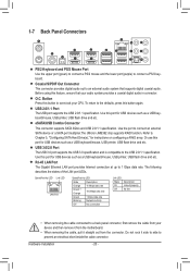
... this port for USB devices such as a USB keyboard/mouse, USB printer, USB flash drive and etc. Do not rock it straight out from the motherboard. • When removing the cable, pull it side to side to Chapter 5, "Configuring SATA Hard Drive(s)," for USB devices such as a USB keyboard/mouse, USB...
... this port for USB devices such as a USB keyboard/mouse, USB printer, USB flash drive and etc. Do not rock it straight out from the motherboard. • When removing the cable, pull it side to side to Chapter 5, "Configuring SATA Hard Drive(s)," for USB devices such as a USB keyboard/mouse, USB...
Manual
Page 22
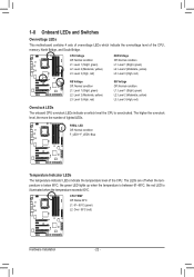
.... The higher the overclock level, the more the number of the CPU, memory, North Bridge, and South Bridge. 1-8 Onboard LEDs and Switches Overvoltage LEDs This motherboard contains 4 sets of overvoltage LEDs which level the CPU is between 61~80oC; CPU TEMP Off: Below 60oC L1: 61~ 80oC (green) L2: Over 80oC...
.... The higher the overclock level, the more the number of the CPU, memory, North Bridge, and South Bridge. 1-8 Onboard LEDs and Switches Overvoltage LEDs This motherboard contains 4 sets of overvoltage LEDs which level the CPU is between 61~80oC; CPU TEMP Off: Below 60oC L1: 61~ 80oC (green) L2: Over 80oC...

Manual
Page 25
... 7) SATA2_0/1/2/3/4/5 8) GSATA3_6/7 9) F_PANEL 10) F_AUDIO 11) SPDIF_O 12) F_USB1/F_USB2/F_USB3 13) F_USB30 14) CLR_CMOS 15) BAT Read the following guidelines before turning on the motherboard. - 25 -
... 7) SATA2_0/1/2/3/4/5 8) GSATA3_6/7 9) F_PANEL 10) F_AUDIO 11) SPDIF_O 12) F_USB1/F_USB2/F_USB3 13) F_USB30 14) CLR_CMOS 15) BAT Read the following guidelines before turning on the motherboard. - 25 -
Manual
Page 26
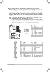
...-pin ATX) Hardware Installation - 26 - Before connecting the power connector, first make sure the power supply is turned off and all the components on the motherboard. The power connector possesses a foolproof design. The 12V power connector mainly supplies power to the power connector in the correct orientation. If a power supply is...
...-pin ATX) Hardware Installation - 26 - Before connecting the power connector, first make sure the power supply is turned off and all the components on the motherboard. The power connector possesses a foolproof design. The 12V power connector mainly supplies power to the power connector in the correct orientation. If a power supply is...


