Manual
Page 1
G1.Sniper LGA1366 socket motherboard for Intel® Core™ i7 processor family User's Manual Rev. 1001 12ME-G1SNIPE-1001R
G1.Sniper LGA1366 socket motherboard for Intel® Core™ i7 processor family User's Manual Rev. 1001 12ME-G1SNIPE-1001R

Manual
Page 3
... Installation Guide included with the product. For detailed product information, carefully read the User's Manual. Check your motherboard looks like this product, GIGABYTE provides the following types of documentations: For quick set-up of this manual may be made by any means without prior notice. For product-related information, check on...
... Installation Guide included with the product. For detailed product information, carefully read the User's Manual. Check your motherboard looks like this product, GIGABYTE provides the following types of documentations: For quick set-up of this manual may be made by any means without prior notice. For product-related information, check on...
Manual
Page 5
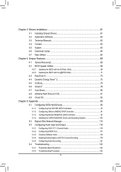
Chapter 3 Drivers Installation 61 3-1 Installing Chipset Drivers 61 3-2 Application Software 62 3-3 Technical Manuals 62 3-4 Contact...63 3-5 System...63 3-6 Download Center 64 3-7 New Utilities...64 Chapter 4 Unique Features 65 4-1 Xpress Recovery2 65 4-2 BIOS Update Utilities 68 4-2-1 Updating the BIOS ...
Chapter 3 Drivers Installation 61 3-1 Installing Chipset Drivers 61 3-2 Application Software 62 3-3 Technical Manuals 62 3-4 Contact...63 3-5 System...63 3-6 Download Center 64 3-7 New Utilities...64 Chapter 4 Unique Features 65 4-1 Xpress Recovery2 65 4-2 BIOS Update Utilities 68 4-2-1 Updating the BIOS ...
Manual
Page 6
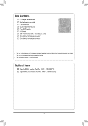
Optional Items 2-port USB 2.0 bracket (Part No. 12CR1-1UB030-5*R) 2-port SATA power cable (Part No. 12CF1-2SERPW-0*R) - 6 - The box contents are for reference only. Box Contents G1.Sniper motherboard Motherboard driver disk User's Manual Quick Installation Guide Four SATA cables I/O Shield 3.5" Front Panel with 2 USB 3.0/2.0 ports One 2-Way SLI bridge connector One 3-Way SLI bridge connector • The box contents above are subject to change without notice. • The motherboard image is for reference only and the actual items shall depend on the product package you obtain.
Optional Items 2-port USB 2.0 bracket (Part No. 12CR1-1UB030-5*R) 2-port SATA power cable (Part No. 12CF1-2SERPW-0*R) - 6 - The box contents are for reference only. Box Contents G1.Sniper motherboard Motherboard driver disk User's Manual Quick Installation Guide Four SATA cables I/O Shield 3.5" Front Panel with 2 USB 3.0/2.0 ports One 2-Way SLI bridge connector One 3-Way SLI bridge connector • The box contents above are subject to change without notice. • The motherboard image is for reference only and the actual items shall depend on the product package you obtain.
Manual
Page 9
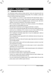
... the motherboard, please have a problem related to wear an electrostatic discharge (ESD) wrist strap when handling electronic com- Prior to installation, carefully read the user's manual and follow these procedures: • Prior to installation, do not remove or break motherboard S/N (Serial Number) sticker or warranty sticker provided by unplugging the power...
... the motherboard, please have a problem related to wear an electrostatic discharge (ESD) wrist strap when handling electronic com- Prior to installation, carefully read the user's manual and follow these procedures: • Prior to installation, do not remove or break motherboard S/N (Serial Number) sticker or warranty sticker provided by unplugging the power...

Manual
Page 15
.... If the push pin is to the CPU. Check that the Male and Female push pins are joined closely. (Refer to your CPU cooler installation manual for instructions on installing the cooler.) Step 5: After the installation, check the back of arrow is to remove the cooler, on the contrary, is inserted...
.... If the push pin is to the CPU. Check that the Male and Female push pins are joined closely. (Refer to your CPU cooler installation manual for instructions on installing the cooler.) Step 5: After the installation, check the back of arrow is to remove the cooler, on the contrary, is inserted...
Manual
Page 18
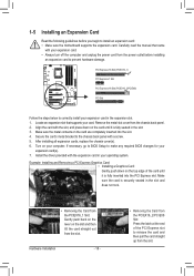
Carefully read the manual that supports your computer. Install the driver provided with your expansion card(s). 7. Hardware Installation - 18 - • Removing the Card from the PCIEX16_2/PCIEX8 Slot: Press ...
Carefully read the manual that supports your computer. Install the driver provided with your expansion card(s). 7. Hardware Installation - 18 - • Removing the Card from the PCIEX16_2/PCIEX8 Slot: Press ...
Manual
Page 19
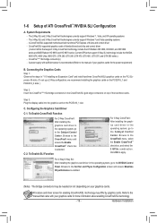
A CrossFireX/SLI-supported motherboard with sufficient power is recommended (Refer to the manual of ATI CrossFireX™/NVIDIA SLI Configuration A. Current GPUs that came with your graphics cards for more information about enabling CrossFireX/SLI technology. - 19 - ...To Enable CrossFireX Function For 2-Way CrossFireX: After installing the graphics card driver in the operating system, go to the manual that support 3-Way SLI technology include the NVIDIA 8800 GTX, 8800 Ultra, 9800 GTX, GTX 260, GTX 280, GTX 470, GTX 480, GTX 570, and...
A CrossFireX/SLI-supported motherboard with sufficient power is recommended (Refer to the manual of ATI CrossFireX™/NVIDIA SLI Configuration A. Current GPUs that came with your graphics cards for more information about enabling CrossFireX/SLI technology. - 19 - ...To Enable CrossFireX Function For 2-Way CrossFireX: After installing the graphics card driver in the operating system, go to the manual that support 3-Way SLI technology include the NVIDIA 8800 GTX, 8800 Ultra, 9800 GTX, GTX 260, GTX 280, GTX 470, GTX 480, GTX 570, and...

Manual
Page 30
... Audio Header) The front panel audio header supports Intel High Definition audio (HD). For information about connecting the S/PDIF digital audio cable, carefully read the manual for digital audio output from your chassis front panel audio module to this header. Incorrect connection between the module connector and the motherboard header will...
... Audio Header) The front panel audio header supports Intel High Definition audio (HD). For information about connecting the S/PDIF digital audio cable, carefully read the manual for digital audio output from your chassis front panel audio module to this header. Incorrect connection between the module connector and the motherboard header will...
Manual
Page 32
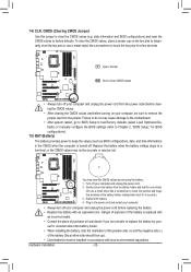
... do so may cause damage to the motherboard. • After system restart, go to BIOS Setup to load factory defaults (select Load Optimized Defaults) or manually configure the BIOS settings (refer to Chapter 2, "BIOS Setup," for BIOS configurations). 15) BAT (Battery) The battery provides power to keep the values (such as...
... do so may cause damage to the motherboard. • After system restart, go to BIOS Setup to load factory defaults (select Load Optimized Defaults) or manually configure the BIOS settings (refer to Chapter 2, "BIOS Setup," for BIOS configurations). 15) BAT (Battery) The battery provides power to keep the values (such as...
Manual
Page 40
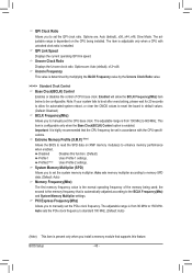
... wait for automated system reboot, or clear the CMOS values to reset the board to default values. (Default: Disabled) BCLK Frequency(Mhz) Allows you to manually set the CPU base clock. Uncore Clock Ratio Displays the Uncore clock ratio. This item is configurable only when the Base Clock(BCLK) Control option... Frequency(Mhz) and System Memory Multiplier settings. Profile2 (Note) Uses Profile 2 settings. Uncore Frequency This value is enabled. Auto sets the PCIe clock frequency to manually set the PCIe clock frequency.
... wait for automated system reboot, or clear the CMOS values to reset the board to default values. (Default: Disabled) BCLK Frequency(Mhz) Allows you to manually set the CPU base clock. Uncore Clock Ratio Displays the Uncore clock ratio. This item is configurable only when the Base Clock(BCLK) Control option... Frequency(Mhz) and System Memory Multiplier settings. Profile2 (Note) Uses Profile 2 settings. Uncore Frequency This value is enabled. Auto sets the PCIe clock frequency to manually set the PCIe clock frequency.

Manual
Page 47
... set this item to None so the system will skip the detection of the device during the POST. (Default) • Manual Allows you wish to enter the parameters manually, refer to manually enter the specifications of the device during the POST for faster system startup. • Auto Lets the BIOS automatically detect SATA...
... set this item to None so the system will skip the detection of the device during the POST. (Default) • Manual Allows you wish to enter the parameters manually, refer to manually enter the specifications of the device during the POST for faster system startup. • Auto Lets the BIOS automatically detect SATA...

Manual
Page 56
... to control the CPU fan speed. Check the fan condition or fan connection when this occurs. (Default: Disabled) CPU Smart FAN Control Allows you to Manual. Current CPU FAN/SYS FAN/FAN1/FAN2/FAN3 Speed (RPM) Displays current CPU/system fan speeds detected by each fan header on the motherboard. Options... system requirements. (Default) Silent Allows the CPU fan to run at different speeds according to control the CPU fan speed under the Slope PWM item. Manual Allows you to the CPU temperature. Current CPU Temperature Displays current CPU temperature. BIOS Setup - 56 -
... to control the CPU fan speed. Check the fan condition or fan connection when this occurs. (Default: Disabled) CPU Smart FAN Control Allows you to Manual. Current CPU FAN/SYS FAN/FAN1/FAN2/FAN3 Speed (RPM) Displays current CPU/system fan speeds detected by each fan header on the motherboard. Options... system requirements. (Default) Silent Allows the CPU fan to run at different speeds according to control the CPU fan speed under the Slope PWM item. Manual Allows you to the CPU temperature. Current CPU Temperature Displays current CPU temperature. BIOS Setup - 56 -
Manual
Page 61
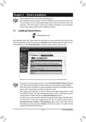
... install. • Please ignore the popup dialog box(es) (e.g. Or click No if you wish to install new GIGABYTE utilities. Or click Install Single Items to manually select the drivers you want to manually select the utilities to install. Click Yes to do so may affect the driver installation. • Some device drivers...
... install. • Please ignore the popup dialog box(es) (e.g. Or click No if you wish to install new GIGABYTE utilities. Or click Install Single Items to manually select the drivers you want to manually select the utilities to install. Click Yes to do so may affect the driver installation. • Some device drivers...

Manual
Page 62
Drivers Installation - 62 - 3-2 Application Software This page displays all the utilities and applications that GIGABYTE develops and some free software. You can click the Install button on the right of an item to install it. 3-3 Technical Manuals This page provides GIGABYTE's application guides, content descriptions for this driver disk, and the motherboard manuals.
Drivers Installation - 62 - 3-2 Application Software This page displays all the utilities and applications that GIGABYTE develops and some free software. You can click the Install button on the right of an item to install it. 3-3 Technical Manuals This page provides GIGABYTE's application guides, content descriptions for this driver disk, and the motherboard manuals.
Manual
Page 68
... enter operating systems like MS-DOS or Window first. During the POST, press the key to access Q-Flash. G1.Sniper F1f . . . . : BIOS Setup : XpressRecovery2 : Boot Menu : Qflash 01/19/2011-X58-ICH10-... through complicated BIOS flashing process. What is saved to enter MS-DOS mode. 4-2 BIOS Update Utilities GIGABYTE motherboards provide two unique BIOS update tools, Q-Flash™ and @BIOS™. What is Q-Flash&#...safety and stability of system safety, users cannot update the backup BIOS manually. Note: You can update the system BIOS without the need to a hard drive in system malfunction....
... enter operating systems like MS-DOS or Window first. During the POST, press the key to access Q-Flash. G1.Sniper F1f . . . . : BIOS Setup : XpressRecovery2 : Boot Menu : Qflash 01/19/2011-X58-ICH10-... through complicated BIOS flashing process. What is saved to enter MS-DOS mode. 4-2 BIOS Update Utilities GIGABYTE motherboards provide two unique BIOS update tools, Q-Flash™ and @BIOS™. What is Q-Flash&#...safety and stability of system safety, users cannot update the backup BIOS manually. Note: You can update the system BIOS without the need to a hard drive in system malfunction....

Manual
Page 71
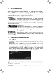
... Update Function" below. 2. Make sure that matches your system after the system restarts. Do not use the G.O.M. (GIGABYTE Online Management) function when using @BIOS. 4. Save the Current BIOS File: Click Save Current BIOS to File to ...GIGABYTE's website and follow the instructions in a corrupted BIOS or a system that is not present on -screen instructions to complete. 3. 4-2-2 Updating the BIOS with an incorrect BIOS file could cause your motherboard model. After Updating the BIOS Restart your motherboard model. Follow the on the @BIOS server site, please manually...
... Update Function" below. 2. Make sure that matches your system after the system restarts. Do not use the G.O.M. (GIGABYTE Online Management) function when using @BIOS. 4. Save the Current BIOS File: Click Save Current BIOS to File to ...GIGABYTE's website and follow the instructions in a corrupted BIOS or a system that is not present on -screen instructions to complete. 3. 4-2-2 Updating the BIOS with an incorrect BIOS file could cause your motherboard model. After Updating the BIOS Restart your motherboard model. Follow the on the @BIOS server site, please manually...
Manual
Page 81
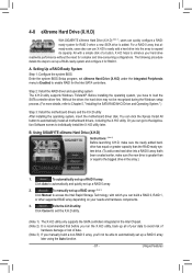
...to exit the X.H.D utility. (Note 1) The X.H.D utility only supports the SATA controllers integrated in the array. ) 1. 4-8 eXtreme Hard Drive (X.H.D) With GIGABYTE eXtreme Hard Drive (X.H.D) (Note 1), users can quickly configure a RAIDready system for RAID 0 when a new SATA drive is greater than the RAID-ready system... data to avoid risk of hardware damage or lost of a button, X.H.D helps to individually install the X.H.D utility later. To manually set up a RAID 0 array. 2. The following procedure details the steps to enable RAID for complex and time-consuming configurations. ...
...to exit the X.H.D utility. (Note 1) The X.H.D utility only supports the SATA controllers integrated in the array. ) 1. 4-8 eXtreme Hard Drive (X.H.D) With GIGABYTE eXtreme Hard Drive (X.H.D) (Note 1), users can quickly configure a RAIDready system for RAID 0 when a new SATA drive is greater than the RAID-ready system... data to avoid risk of hardware damage or lost of a button, X.H.D helps to individually install the X.H.D utility later. To manually set up a RAID 0 array. 2. The following procedure details the steps to enable RAID for complex and time-consuming configurations. ...

Manual
Page 89
...under the Select Disks item. e. On Request allows users to update data from the master drive to the recovery drive manually using the Intel Rapid Storage Technology utility in the system. Intel(R) Matrix Storage Manager option ROM v8.9.1.1002 ICH10R/DO wRAID5... Disks : Select Disks Strip Size : N/A Capacity : 0.0 GB Sync : Continuous Create Volume [ HELP ] Select a sync option: On Request: volume is updated manually Continuous: volume is updated automatically [hi]-Change [TAB]-Next [ESC]-Previous Menu Figure 11 [ENTER]-Select Step 5: Finally press on the hard drive you want...
...under the Select Disks item. e. On Request allows users to update data from the master drive to the recovery drive manually using the Intel Rapid Storage Technology utility in the system. Intel(R) Matrix Storage Manager option ROM v8.9.1.1002 ICH10R/DO wRAID5... Disks : Select Disks Strip Size : N/A Capacity : 0.0 GB Sync : Continuous Create Volume [ HELP ] Select a sync option: On Request: volume is updated manually Continuous: volume is updated automatically [hi]-Change [TAB]-Next [ESC]-Previous Menu Figure 11 [ENTER]-Select Step 5: Finally press on the hard drive you want...

Manual
Page 108
... to replace a failed drive to rebuild a RAID 1 array. (Note: The new drive must have to Non-RAID "Degrad2e.d DvoeluetmeeRaAnIdDdVisokluamvaeilable for more details). Reset Disks to manually rebuild the array in the operating system (see the next page for rebuilding detected. Select the port of restoring data to be performed after you...
... to replace a failed drive to rebuild a RAID 1 array. (Note: The new drive must have to Non-RAID "Degrad2e.d DvoeluetmeeRaAnIdDdVisokluamvaeilable for more details). Reset Disks to manually rebuild the array in the operating system (see the next page for rebuilding detected. Select the port of restoring data to be performed after you...


