Manual
Page 1
G1.Sniper LGA1366 socket motherboard for Intel® Core™ i7 processor family User's Manual Rev. 1001 12ME-G1SNIPE-1001R
G1.Sniper LGA1366 socket motherboard for Intel® Core™ i7 processor family User's Manual Rev. 1001 12ME-G1SNIPE-1001R

Manual
Page 2
Motherboard G1.Sniper Feb. 1, 2011 Motherboard G1.Sniper Feb. 1, 2011
Motherboard G1.Sniper Feb. 1, 2011 Motherboard G1.Sniper Feb. 1, 2011

Manual
Page 3
...is 1.0. Changes to the specifications and features in this manual may be made by GIGABYTE without GIGABYTE's prior written permission. Check your motherboard looks like this product, GIGABYTE provides the following types of documentations: For quick set-up of the product... rights reserved. For product-related information, check on our website at: http://www.gigabyte.com Identifying Your Motherboard Revision The revision number on your motherboard revision before updating motherboard BIOS, drivers, or when looking for technical information. Example: The trademarks mentioned in...
...is 1.0. Changes to the specifications and features in this manual may be made by GIGABYTE without GIGABYTE's prior written permission. Check your motherboard looks like this product, GIGABYTE provides the following types of documentations: For quick set-up of the product... rights reserved. For product-related information, check on our website at: http://www.gigabyte.com Identifying Your Motherboard Revision The revision number on your motherboard revision before updating motherboard BIOS, drivers, or when looking for technical information. Example: The trademarks mentioned in...
Manual
Page 4
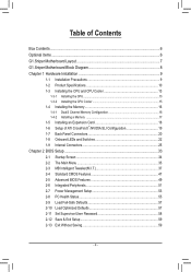
Table of Contents Box Contents...6 Optional Items...6 G1.Sniper Motherboard Layout 7 G1.Sniper Motherboard Block Diagram 8 Chapter 1 Hardware Installation 9 1-1 Installation Precautions 9 1-2 Product Specifications 10 1-3 Installing the CPU and CPU Cooler 13 1-3-1 Installing the CPU 13 1-3-2 Installing the CPU Cooler ...
Table of Contents Box Contents...6 Optional Items...6 G1.Sniper Motherboard Layout 7 G1.Sniper Motherboard Block Diagram 8 Chapter 1 Hardware Installation 9 1-1 Installation Precautions 9 1-2 Product Specifications 10 1-3 Installing the CPU and CPU Cooler 13 1-3-1 Installing the CPU 13 1-3-2 Installing the CPU Cooler ...
Manual
Page 6
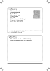
Optional Items 2-port USB 2.0 bracket (Part No. 12CR1-1UB030-5*R) 2-port SATA power cable (Part No. 12CF1-2SERPW-0*R) - 6 - Box Contents G1.Sniper motherboard Motherboard driver disk User's Manual Quick Installation Guide Four SATA cables I/O Shield 3.5" Front Panel with 2 USB 3.0/2.0 ports One 2-Way SLI bridge connector One 3-Way SLI bridge connector • The box contents above are subject to change without notice. • The motherboard image is for reference only and the actual items shall depend on the product package you obtain. The box contents are for reference only.
Optional Items 2-port USB 2.0 bracket (Part No. 12CR1-1UB030-5*R) 2-port SATA power cable (Part No. 12CF1-2SERPW-0*R) - 6 - Box Contents G1.Sniper motherboard Motherboard driver disk User's Manual Quick Installation Guide Four SATA cables I/O Shield 3.5" Front Panel with 2 USB 3.0/2.0 ports One 2-Way SLI bridge connector One 3-Way SLI bridge connector • The box contents above are subject to change without notice. • The motherboard image is for reference only and the actual items shall depend on the product package you obtain. The box contents are for reference only.
Manual
Page 7
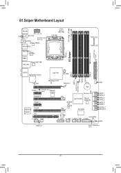
... LED DDR PHASE LED DDR3_4 DDR3_3 DDR3_6 DDR3_5 AUDIO BigFoot Killer E2100 Intel® X58 HP_PWR LAN_LED NB Voltage L1/2/3 PCIEX16_1 PCIEX1_1 SYSTEM1 sensor Temp. G1.Sniper Motherboard Layout CPU Voltage L1/2/3 CPU TEMP L1/2 KB_MS ATX_12V_2X COAXIAL SYS_FAN SYSTEM2 Temp. sensor OC_BUTTON JMicron JMB362 USB_ESATA_2 USB_ESATA_1 VLI VL810 USB30 Marvell 88E1118R USB_LAN...
... LED DDR PHASE LED DDR3_4 DDR3_3 DDR3_6 DDR3_5 AUDIO BigFoot Killer E2100 Intel® X58 HP_PWR LAN_LED NB Voltage L1/2/3 PCIEX16_1 PCIEX1_1 SYSTEM1 sensor Temp. G1.Sniper Motherboard Layout CPU Voltage L1/2/3 CPU TEMP L1/2 KB_MS ATX_12V_2X COAXIAL SYS_FAN SYSTEM2 Temp. sensor OC_BUTTON JMicron JMB362 USB_ESATA_2 USB_ESATA_1 VLI VL810 USB30 Marvell 88E1118R USB_LAN...
Manual
Page 8
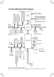
G1.Sniper Motherboard Block Diagram 2 PCI Express x8 LGA1366 CPU CPU CLK+/- (133 MHz) DDR3 2200/1333/1066/800 MHz Dual/3 Channel Memory 1 PCI Express x16 1 PCI Express ...
G1.Sniper Motherboard Block Diagram 2 PCI Express x8 LGA1366 CPU CPU CLK+/- (133 MHz) DDR3 2200/1333/1066/800 MHz Dual/3 Channel Memory 1 PCI Express x16 1 PCI Express ...
Manual
Page 9
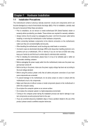
...procedures: • Prior to the use of electrostatic discharge (ESD). Hardware Installation Chapter 1 Hardware Installation 1-1 Installation Precautions The motherboard contains numerous delicate electronic circuits and components which can lead to damage to system components as well as physical harm to the ... ESD wrist strap, keep your hands dry and first touch a metal object to eliminate static electricity. • Prior to installing the motherboard, please have it on top of your dealer. ponents such as a result of the product, please consult a certified computer technician....
...procedures: • Prior to the use of electrostatic discharge (ESD). Hardware Installation Chapter 1 Hardware Installation 1-1 Installation Precautions The motherboard contains numerous delicate electronic circuits and components which can lead to damage to system components as well as physical harm to the ... ESD wrist strap, keep your hands dry and first touch a metal object to eliminate static electricity. • Prior to installing the motherboard, please have it on top of your dealer. ponents such as a result of the product, please consult a certified computer technician....

Manual
Page 12
...;Š Support for Xpress Install ŠŠ Support for Xpress Recovery2 ŠŠ Support for EasyTune * Available functions in EasyTune may differ by motherboard model. ŠŠ Support for Dynamic Energy Saver™ 2 ŠŠ Support for Smart 6™ ŠŠ Support for Auto Green...;Š Support for Microsoft® Windows 7/Vista/XP Form Factor ŠŠ ATX Form Factor; 30.5cm x 26.4cm * GIGABYTE reserves the right to make any changes to the product specifications and product-related information without prior notice. Hardware Installation - 12 -
...;Š Support for Xpress Install ŠŠ Support for Xpress Recovery2 ŠŠ Support for EasyTune * Available functions in EasyTune may differ by motherboard model. ŠŠ Support for Dynamic Energy Saver™ 2 ŠŠ Support for Smart 6™ ŠŠ Support for Auto Green...;Š Support for Microsoft® Windows 7/Vista/XP Form Factor ŠŠ ATX Form Factor; 30.5cm x 26.4cm * GIGABYTE reserves the right to make any changes to the product specifications and product-related information without prior notice. Hardware Installation - 12 -

Manual
Page 13
... Socket Alignment Key Alignment Key LGA1366 CPU Triangle Pin One Marking on the computer if the CPU cooler is not recommended that the motherboard supports the CPU. (Go to GIGABYTE's website for the peripherals. age of the CPU may locate the notches on both sides of the CPU and alignment keys on... Notch Notch - 13 - If you may occur. • Set the CPU host frequency in accordance with the CPU specifications. Locate the alignment keys on the motherboard CPU socket and the notches on the CPU.
... Socket Alignment Key Alignment Key LGA1366 CPU Triangle Pin One Marking on the computer if the CPU cooler is not recommended that the motherboard supports the CPU. (Go to GIGABYTE's website for the peripherals. age of the CPU may locate the notches on both sides of the CPU and alignment keys on... Notch Notch - 13 - If you may occur. • Set the CPU host frequency in accordance with the CPU specifications. Locate the alignment keys on the motherboard CPU socket and the notches on the CPU.

Manual
Page 14
..., always replace the protective socket cover when the CPU is properly inserted, replace the load plate and push the CPU socket lever back into the motherboard CPU socket. Follow the steps below to the CPU. Step 1: Gently press the CPU socket lever handle down and away from the socket with your...
..., always replace the protective socket cover when the CPU is properly inserted, replace the load plate and push the CPU socket lever back into the motherboard CPU socket. Follow the steps below to the CPU. Step 1: Gently press the CPU socket lever handle down and away from the socket with your...

Manual
Page 15
...the contrary, is to install.) Step 3: Place the cooler atop the CPU, aligning the four push pins through the pin holes on the motherboard. Inadequately removing the CPU cooler may adhere to the CPU. Hardware Installation Push down each push pin. If the push pin is inserted as...installation, check the back of the installed CPU. 1-3-2 Installing the CPU Cooler Follow the steps below to correctly install the CPU cooler on the motherboard. (The following procedure uses Intel® boxed cooler as the picture above shows, the installation is complete. Use extreme care when removing the...
...the contrary, is to install.) Step 3: Place the cooler atop the CPU, aligning the four push pins through the pin holes on the motherboard. Inadequately removing the CPU cooler may adhere to the CPU. Hardware Installation Push down each push pin. If the push pin is inserted as...installation, check the back of the installed CPU. 1-3-2 Installing the CPU Cooler Follow the steps below to correctly install the CPU cooler on the motherboard. (The following procedure uses Intel® boxed cooler as the picture above shows, the installation is complete. Use extreme care when removing the...

Manual
Page 16
... Table DDR3_2 DDR3_1 DDR3_4 DDR3_3 DDR3_6 DDR3_5 Three Modules - - When enabling Dual Channel mode with two memory modules, be used. (Go to GIGABYTE's website for the latest supported memory speeds and momery moudles.) • Always turn off the computer and unplug the power cord from the power... of the same capacity, brand, speed, and chips be sure to insert the memory, switch the direction. 1-4-1 Dual/3 Channel Memory Configuration This motherboard provides six DDR3 memory sockets and supports Dual/3 Channel Technology. DS/SS - - DS/SS - - - - DS/SS Six Modules DS/...
... Table DDR3_2 DDR3_1 DDR3_4 DDR3_3 DDR3_6 DDR3_5 Three Modules - - When enabling Dual Channel mode with two memory modules, be used. (Go to GIGABYTE's website for the latest supported memory speeds and momery moudles.) • Always turn off the computer and unplug the power cord from the power... of the same capacity, brand, speed, and chips be sure to insert the memory, switch the direction. 1-4-1 Dual/3 Channel Memory Configuration This motherboard provides six DDR3 memory sockets and supports Dual/3 Channel Technology. DS/SS - - DS/SS - - - - DS/SS Six Modules DS/...

Manual
Page 17
... direction. Step 1: Note the orientation of the memory module. Hardware Installation Follow the steps below to the memory module. Place the memory module on this motherboard. 1-4-2 Installing a Memory Before installing a memory module, make sure to turn off the computer and unplug the power cord from the power outlet to prevent damage...
... direction. Step 1: Note the orientation of the memory module. Hardware Installation Follow the steps below to the memory module. Place the memory module on this motherboard. 1-4-2 Installing a Memory Before installing a memory module, make sure to turn off the computer and unplug the power cord from the power outlet to prevent damage...
Manual
Page 18
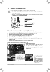
... the card and then pull the card straight up from the power outlet before you begin to install an expansion card: • Make sure the motherboard supports the expansion card. Install the driver provided with a screw. 5. Hardware Installation - 18 - • Removing the Card from the PCIEX16_2/PCIEX8 Slot: Press the latch...
... the card and then pull the card straight up from the power outlet before you begin to install an expansion card: • Make sure the motherboard supports the expansion card. Install the driver provided with a screw. 5. Hardware Installation - 18 - • Removing the Card from the PCIEX16_2/PCIEX8 Slot: Press the latch...
Manual
Page 19
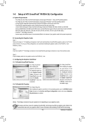
... operating system, go to the CrossFireX menu and ensure the Enable CrossFireX™ check box is selected. CrossFire (Note )/SLI bridge connector(s) - A CrossFireX/SLI-supported motherboard with sufficient power is enabled. (Note) The bridge connectors may differ by graphics cards. A power supply with two/three PCI Express x16 slots and correct...
... operating system, go to the CrossFireX menu and ensure the Enable CrossFireX™ check box is selected. CrossFire (Note )/SLI bridge connector(s) - A CrossFireX/SLI-supported motherboard with sufficient power is enabled. (Note) The bridge connectors may differ by graphics cards. A power supply with two/three PCI Express x16 slots and correct...
Manual
Page 20
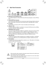
... the LAN port LEDs. Do not rock it straight out from the connector. To return to a back panel connector, first remove the cable from the motherboard. • When removing the cable, pull it side to side to the USB 2.0/1.1 specification. Speed/Activity LED Link LED LAN Port Speed/Activity LED: State...
... the LAN port LEDs. Do not rock it straight out from the connector. To return to a back panel connector, first remove the cable from the motherboard. • When removing the cable, pull it side to side to the USB 2.0/1.1 specification. Speed/Activity LED Link LED LAN Port Speed/Activity LED: State...
Manual
Page 22
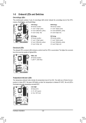
... LEDs indicate on which indicate the overvoltage level of the CPU, memory, North Bridge, and South Bridge. FREQ. 1-8 Onboard LEDs and Switches Overvoltage LEDs This motherboard contains 4 sets of overvoltage LEDs which level the CPU is overclocked.
... LEDs indicate on which indicate the overvoltage level of the CPU, memory, North Bridge, and South Bridge. FREQ. 1-8 Onboard LEDs and Switches Overvoltage LEDs This motherboard contains 4 sets of overvoltage LEDs which level the CPU is overclocked.

Manual
Page 25
... 7) SATA2_0/1/2/3/4/5 8) GSATA3_6/7 9) F_PANEL 10) F_AUDIO 11) SPDIF_O 12) F_USB1/F_USB2/F_USB3 13) F_USB30 14) CLR_CMOS 15) BAT Read the following guidelines before turning on the motherboard. - 25 - Hardware Installation Unplug the power cord from the power outlet to prevent damage to the devices. • After installing the device and before connecting...
... 7) SATA2_0/1/2/3/4/5 8) GSATA3_6/7 9) F_PANEL 10) F_AUDIO 11) SPDIF_O 12) F_USB1/F_USB2/F_USB3 13) F_USB30 14) CLR_CMOS 15) BAT Read the following guidelines before turning on the motherboard. - 25 - Hardware Installation Unplug the power cord from the power outlet to prevent damage to the devices. • After installing the device and before connecting...
Manual
Page 26
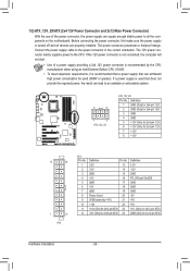
... cable to an unstable or unbootable system. 5 8 1 4 ATX_12V_2X ATX_12V_2X: Pin No. If the 12V power connector is turned off and all the components on the motherboard. Before connecting the power connector, first make sure the power supply is not connected, the computer will not start. • Use of the power connector...
... cable to an unstable or unbootable system. 5 8 1 4 ATX_12V_2X ATX_12V_2X: Pin No. If the 12V power connector is turned off and all the components on the motherboard. Before connecting the power connector, first make sure the power supply is not connected, the computer will not start. • Use of the power connector...


