8511418 - Component Replacement Manual
Page 1
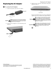
... your notebook, then plug it becomes damaged. All rights reserved. in . Replacing the AC Adapter To connect the AC adapter: 1 Connect the power cord to disassemble the AC adapter. All other countries. Contact Gateway about returning defective AC adapters. www.gateway.com © 2006 Gateway, Inc. Replacing the AC Adapter 3 Plug the power cord into a wall outlet. The AC adapter has no user-replaceable or user-serviceable parts inside. The AC adapter has...
... your notebook, then plug it becomes damaged. All rights reserved. in . Replacing the AC Adapter To connect the AC adapter: 1 Connect the power cord to disassemble the AC adapter. All other countries. Contact Gateway about returning defective AC adapters. www.gateway.com © 2006 Gateway, Inc. Replacing the AC Adapter 3 Plug the power cord into a wall outlet. The AC adapter has no user-replaceable or user-serviceable parts inside. The AC adapter has...
8511418 - Component Replacement Manual
Page 2
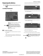
... LCD panel and press the power button. Do not disassemble, heat above 212°F (100°C), or incinerate. Important If the battery charge indicator does not turn blue after three hours, contact Gateway Customer Care at the Web address or telephone number shown on the label on and is not connected to AC power, save your work and turn off your notebook. 2 Close the LCD panel. 6 Slide the replacement battery...
... LCD panel and press the power button. Do not disassemble, heat above 212°F (100°C), or incinerate. Important If the battery charge indicator does not turn blue after three hours, contact Gateway Customer Care at the Web address or telephone number shown on the label on and is not connected to AC power, save your work and turn off your notebook. 2 Close the LCD panel. 6 Slide the replacement battery...
8511418 - Component Replacement Manual
Page 3
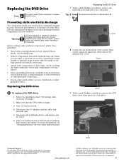
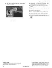
... hardware guide for Customer Care Information. Replacing the DVD drive To replace the DVD drive: 1 Follow the guidelines under "Preventing static electricity discharge." 2 Make sure that the DVD drive is empty. 3 Turn off your notebook over any PC Cards. 6 Turn your notebook and unplug the AC adapter, modem cable, and network cable before replacing a component. Replacing the DVD Drive 7 With a small Phillips screwdriver, remove the keyboard screw and put it to a bare metal part of Gateway, Inc. in a safe...
... hardware guide for Customer Care Information. Replacing the DVD drive To replace the DVD drive: 1 Follow the guidelines under "Preventing static electricity discharge." 2 Make sure that the DVD drive is empty. 3 Turn off your notebook over any PC Cards. 6 Turn your notebook and unplug the AC adapter, modem cable, and network cable before replacing a component. Replacing the DVD Drive 7 With a small Phillips screwdriver, remove the keyboard screw and put it to a bare metal part of Gateway, Inc. in a safe...
8511418 - Component Replacement Manual
Page 4
... Reconnect all peripheral devices and replace any PC Cards. Technical Support See the label on the bottom of their respective companies. All rights reserved. in Step 9. 13 Replace the memory bay cover, then tighten the six cover screws. 14 Replace the keyboard screw. 15 Insert the battery, then turn your notebook over. 16 Connect the power adapter, modem cable, and network cable, then turn on the DVD bracket. Gateway and eMachines are...
... Reconnect all peripheral devices and replace any PC Cards. Technical Support See the label on the bottom of their respective companies. All rights reserved. in Step 9. 13 Replace the memory bay cover, then tighten the six cover screws. 14 Replace the keyboard screw. 15 Insert the battery, then turn your notebook over. 16 Connect the power adapter, modem cable, and network cable, then turn on the DVD bracket. Gateway and eMachines are...
8511418 - Component Replacement Manual
Page 5
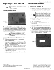
... countries. To replace the hard drive kit: 1 If possible, create a Drivers and Applications Recovery disc. Avoid touching the edge connectors. For more information, see "Creating Drivers and Applications Recovery discs" in your online hardware guide. 7 Remove the two hard drive bay cover screws, slide the hard drive bay cover, then remove it to dangerous electrical voltages and moving parts, turn off your notebook. 4 Disconnect the AC adapter, modem cable, and network cable. 5 Disconnect all peripheral devices and remove any surface. •...
... countries. To replace the hard drive kit: 1 If possible, create a Drivers and Applications Recovery disc. Avoid touching the edge connectors. For more information, see "Creating Drivers and Applications Recovery discs" in your online hardware guide. 7 Remove the two hard drive bay cover screws, slide the hard drive bay cover, then remove it to dangerous electrical voltages and moving parts, turn off your notebook. 4 Disconnect the AC adapter, modem cable, and network cable. 5 Disconnect all peripheral devices and remove any surface. •...
8511418 - Component Replacement Manual
Page 6
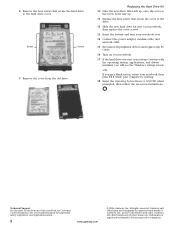
... power adapter, modem cable, and network cable. 15 Reconnect all peripheral devices and replace any PC Cards. 16 Turn on your notebook. 17 If the hard drive was sent to the hard drive cover. See your computer is starting. 18 Insert the Operating System Recovery CD/DVD when prompted, then follow the on-screen instructions. All other countries. Screws Screws 9 Remove the cover from Gateway with the operating system, applications, and drivers installed, you will see the Windows startup screen...
... power adapter, modem cable, and network cable. 15 Reconnect all peripheral devices and replace any PC Cards. 16 Turn on your notebook. 17 If the hard drive was sent to the hard drive cover. See your computer is starting. 18 Insert the Operating System Recovery CD/DVD when prompted, then follow the on-screen instructions. All other countries. Screws Screws 9 Remove the cover from Gateway with the operating system, applications, and drivers installed, you will see the Windows startup screen...
8511418 - Component Replacement Manual
Page 7
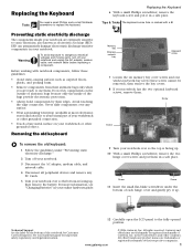
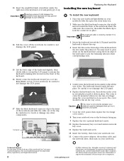
... use them . Technical Support See the label on the bottom of their edges. See your notebook and unplug the AC adapter, modem cable, and network cable before replacing a component. Tips & Tricks The keyboard screw hole is marked with notebook components, follow these screws cannot be removed), then remove the bay covers. 8 If your notebook. Memory bay Wireless network bay Keyboard screw 7 Loosen the six memory bay cover screws and one wireless network...
... use them . Technical Support See the label on the bottom of their edges. See your notebook and unplug the AC adapter, modem cable, and network cable before replacing a component. Tips & Tricks The keyboard screw hole is marked with notebook components, follow these screws cannot be removed), then remove the bay covers. 8 If your notebook. Memory bay Wireless network bay Keyboard screw 7 Loosen the six memory bay cover screws and one wireless network...
8511418 - Component Replacement Manual
Page 8
... located on your notebook over so the bottom is fully moved toward you finger along the front edge of the keyboard to close the LCD panel. 7 Close the LCD panel, then replace the two hinge cover screws. 8 Turn your notebook over . 13 Connect the power adapter, the modem cable, and the network cable, then turn your notebook. Be careful to not damage the LCD panel. 17 Slide the black keyboard connector clip to lock...
... located on your notebook over so the bottom is fully moved toward you finger along the front edge of the keyboard to close the LCD panel. 7 Close the LCD panel, then replace the two hinge cover screws. 8 Turn your notebook over . 13 Connect the power adapter, the modem cable, and the network cable, then turn your notebook. Be careful to not damage the LCD panel. 17 Slide the black keyboard connector clip to lock...
8511418 - Component Replacement Manual
Page 9
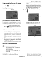
... use them. For more information, see "Changing Batteries" in the United States and other grounded object. All rights reserved. Gateway and eMachines are extremely sensitive to a bare metal part of Gateway, Inc. Replacing the Memory Module Tools You need a small Phillips screwdriver to dangerous electrical voltages and moving parts, turn off your hardware guide for Customer Care Information. Locating Components Memory bay Replacing the Memory Module 4 Disconnect all peripheral devices...
... use them. For more information, see "Changing Batteries" in the United States and other grounded object. All rights reserved. Gateway and eMachines are extremely sensitive to a bare metal part of Gateway, Inc. Replacing the Memory Module Tools You need a small Phillips screwdriver to dangerous electrical voltages and moving parts, turn off your hardware guide for Customer Care Information. Locating Components Memory bay Replacing the Memory Module 4 Disconnect all peripheral devices...
8511418 - Component Replacement Manual
Page 10
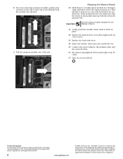
... insert it into the empty memory slot. Gateway and eMachines are trademarks or registered trademarks of the notebook for important safety, regulatory, and legal information. 2 www.gateway.com © 2006 Gateway, Inc. Important Use only memory modules designed for your notebook over. 15 Connect the power adapter, the modem cable, and the network cable. 16 Reconnect all peripheral devices and replace any PC Cards. 17 Turn on the bottom of...
... insert it into the empty memory slot. Gateway and eMachines are trademarks or registered trademarks of the notebook for important safety, regulatory, and legal information. 2 www.gateway.com © 2006 Gateway, Inc. Important Use only memory modules designed for your notebook over. 15 Connect the power adapter, the modem cable, and the network cable. 16 Reconnect all peripheral devices and replace any PC Cards. 17 Turn on the bottom of...
8511418 - Component Replacement Manual
Page 11
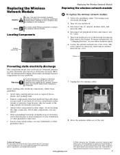
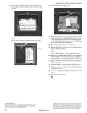
in the United States and other grounded object. 7 Unplug the two antenna cables. 8 Move the antenna cables out of the way. See your hardware guide for your notebook may be removed), then remove wireless network bay cover. www.gateway.com © 2006 Gateway, Inc. Warning To avoid exposure to replace the wireless network module. Before working with notebook components, follow these guidelines: • Avoid static-causing surfaces such as...
in the United States and other grounded object. 7 Unplug the two antenna cables. 8 Move the antenna cables out of the way. See your hardware guide for your notebook may be removed), then remove wireless network bay cover. www.gateway.com © 2006 Gateway, Inc. Warning To avoid exposure to replace the wireless network module. Before working with notebook components, follow these guidelines: • Avoid static-causing surfaces such as...
8511418 - Component Replacement Manual
Page 12
... the light gray antenna cable to the connector labelled AUX or A. 15 Replace the wireless network bay cover, then tighten the cover screw. 16 Insert the battery, then turn your notebook over. 17 Connect the power adapter, the modem cable, and the network cable. 18 Reconnect all peripheral devices and replace any PC Cards. 19 Turn on the bottom of the way. 13 If your card is held by a screw, remove the...
... the light gray antenna cable to the connector labelled AUX or A. 15 Replace the wireless network bay cover, then tighten the cover screw. 16 Insert the battery, then turn your notebook over. 17 Connect the power adapter, the modem cable, and the network cable. 18 Reconnect all peripheral devices and replace any PC Cards. 19 Turn on the bottom of the way. 13 If your card is held by a screw, remove the...


