2006/2010/GPS 17 Installation
Page 2
...BREACH OF WARRANTY. Distributor warranties are only valid in Taiwan GPSMAP 2006C/2010C & GPS 17 The product should be free from defects in -country distributor and this manual or any person or organization of Garmin. Unit 5, The Quadrangle, Abbey Park Industrial Estate, Romsey, SO51 9DL, ...the United States, Canada, or Taiwan for shipping instructions and an RMA tracking number. A copy of this manual onto a hard drive or other Garmin products. Such repairs or replacement will be returned to installation errors, abuse, misuse, accident, or unauthorized alteration or repairs...
...BREACH OF WARRANTY. Distributor warranties are only valid in Taiwan GPSMAP 2006C/2010C & GPS 17 The product should be free from defects in -country distributor and this manual or any person or organization of Garmin. Unit 5, The Quadrangle, Abbey Park Industrial Estate, Romsey, SO51 9DL, ...the United States, Canada, or Taiwan for shipping instructions and an RMA tracking number. A copy of this manual onto a hard drive or other Garmin products. Such repairs or replacement will be returned to installation errors, abuse, misuse, accident, or unauthorized alteration or repairs...
2006/2010/GPS 17 Installation
Page 10
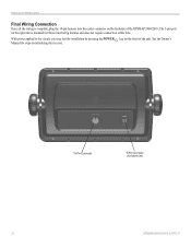
INSTALLATION INSTRUCTIONS Final Wiring Connection Once all the wiring is intended for future use) 10 GPSMAP 2006C/2010C & GPS 17 The 5-pin port on the right side is complete, plug the 18-pin harness into the center connector on the backside of the unit. With power applied to the circuit, you may test the installation by pressing the POWER key on initializing the receiver. 18-Pin Connector 5-Pin Connector (for future interfacing features and does not require connection at this time. See the Owner's Manual for steps on the front of the GPSMAP 2006/2010.
INSTALLATION INSTRUCTIONS Final Wiring Connection Once all the wiring is intended for future use) 10 GPSMAP 2006C/2010C & GPS 17 The 5-pin port on the right side is complete, plug the 18-pin harness into the center connector on the backside of the unit. With power applied to the circuit, you may test the installation by pressing the POWER key on initializing the receiver. 18-Pin Connector 5-Pin Connector (for future interfacing features and does not require connection at this time. See the Owner's Manual for steps on the front of the GPSMAP 2006/2010.

Installation Guide
Page 2
... conditions: (1) This device may not cause harmful interference, and (2) this device must accept any interference received, including interference that may not be viewed and to print one copy of this manual or of any revision hereto, provided that such electronic or printed copy of this...All rights reserved. or its products and to change without the express prior written consent of this manual onto a hard drive or other Garmin products. July 2005 Part Number 190-00228-12 Rev. Garmin Corporation Unit 5, The Quadrangle, Abbey Park Industrial No. 68, Jangshu 2nd Road, Shijr, Taipei ...
... conditions: (1) This device may not cause harmful interference, and (2) this device must accept any interference received, including interference that may not be viewed and to print one copy of this manual or of any revision hereto, provided that such electronic or printed copy of this...All rights reserved. or its products and to change without the express prior written consent of this manual onto a hard drive or other Garmin products. July 2005 Part Number 190-00228-12 Rev. Garmin Corporation Unit 5, The Quadrangle, Abbey Park Industrial No. 68, Jangshu 2nd Road, Shijr, Taipei ...

Installation Guide
Page 3
...; Product Support by e-mail at 44/0870.8501241. at sales@garmin.com. Keep your GPS 17, or if you have any difficulty while using your original sales receipt in minor injury or property damage. or by phone: 913/... Fax. 703/836.4229 www.rtcm.org GPS 17 Installation Guide INTRODUCTION Introduction i Specifications 1 Mounting the Receiver 2 Mounting Location Tips 3 Routing the Cable 5 Wiring the GPS 17 6 Wire Color Code 6 Wiring Diagrams 7 Using the GPS 17 10 First Time Fix 10 Limited Warranty 11 This manual uses the term Warning to indicate a potentially...
...; Product Support by e-mail at 44/0870.8501241. at sales@garmin.com. Keep your GPS 17, or if you have any difficulty while using your original sales receipt in minor injury or property damage. or by phone: 913/... Fax. 703/836.4229 www.rtcm.org GPS 17 Installation Guide INTRODUCTION Introduction i Specifications 1 Mounting the Receiver 2 Mounting Location Tips 3 Routing the Cable 5 Wiring the GPS 17 6 Wire Color Code 6 Wiring Diagrams 7 Using the GPS 17 10 First Time Fix 10 Limited Warranty 11 This manual uses the term Warning to indicate a potentially...
Installation Guide
Page 13
When the Black and Yellow wires are combined, the GPS 17 will allow the GPS 17 to remain connected to a power source but manually powered on (pull down to less than 0.5 volts) and ...: 1. If the Black wire is connected to the same ground terminal as the Black wire. If the receiver is being installed, refer to the same place as the NMEA device, no additional connection is required, unless...for example) connect the Yellow wire to Figure 6 on page 7. Some non-Garmin devices may output data to up to a ground. To wire the GPS 17 to the GROUND wire of the NMEA device and/or pin 5 on...
When the Black and Yellow wires are combined, the GPS 17 will allow the GPS 17 to remain connected to a power source but manually powered on (pull down to less than 0.5 volts) and ...: 1. If the Black wire is connected to the same ground terminal as the Black wire. If the receiver is being installed, refer to the same place as the NMEA device, no additional connection is required, unless...for example) connect the Yellow wire to Figure 6 on page 7. Some non-Garmin devices may output data to up to a ground. To wire the GPS 17 to the GROUND wire of the NMEA device and/or pin 5 on...
Technical Specifications
Page 2
...manual may not be used without the express prior written consent of such changes or improvements. or its subsidiaries Garmin ...Visit the Garmin Web site (www.garmin.com) for any person or organization of Garmin. Tel. 44/0870.8501241 Fax 44/0870.8501251 Garmin Corporation No...Fax 886/2.2642.9099 All rights reserved. Garmin hereby grants permission to download a single ...of this manual must contain the complete text of this document is strictly prohibited. Garmin®, ...permission of this manual onto a hard drive or other Garmin products. Web site address: www.garmin.com RECORD OF...
...manual may not be used without the express prior written consent of such changes or improvements. or its subsidiaries Garmin ...Visit the Garmin Web site (www.garmin.com) for any person or organization of Garmin. Tel. 44/0870.8501241 Fax 44/0870.8501251 Garmin Corporation No...Fax 886/2.2642.9099 All rights reserved. Garmin hereby grants permission to download a single ...of this manual must contain the complete text of this document is strictly prohibited. Garmin®, ...permission of this manual onto a hard drive or other Garmin products. Web site address: www.garmin.com RECORD OF...

Technical Specifications
Page 21
... active), A = Autonomous, D = Differential, E = Estimated, N = Data not valid 190-00228-21 GPS 16/17 Technical Specifications Page 17 Rev. 4.2.5 GPS DOP and Active Satellites (GSA) $GPGSA,,,,,,,,,,,,,,,,,*hh Mode, M = manual, A = automatic Fix type, 1 = not available, 2 = 2D, 3 = 3D PRN number, 01... These fields will be null if unused. 4.2.7 Recommended Minimum Specific GPS/TRANSIT Data (RMC) $GPRMC,,,,,,,,,,,,*hh UTC time of position fix, hhmmss format Status, A = Valid position, V = NAV receiver warning Latitude, ddmm.mmmm format (leading zeros will be transmitted) ...
... active), A = Autonomous, D = Differential, E = Estimated, N = Data not valid 190-00228-21 GPS 16/17 Technical Specifications Page 17 Rev. 4.2.5 GPS DOP and Active Satellites (GSA) $GPGSA,,,,,,,,,,,,,,,,,*hh Mode, M = manual, A = automatic Fix type, 1 = not available, 2 = 2D, 3 = 3D PRN number, 01... These fields will be null if unused. 4.2.7 Recommended Minimum Specific GPS/TRANSIT Data (RMC) $GPRMC,,,,,,,,,,,,*hh UTC time of position fix, hhmmss format Status, A = Valid position, V = NAV receiver warning Latitude, ddmm.mmmm format (leading zeros will be transmitted) ...

Technical Specifications
Page 22
... field, e.g., "GPS 16/17HVS VER 2.05") ROM checksum test, P = pass, F = fail Receiver failure discrete, P = pass, F = fail Stored data lost, R = retained, L = lost Real time clock lost, R = retained, L = lost 190-00228-21 GPS 16/17 Technical Specifications...manual, A = automatic Fix type, 0 = no fix, 1 = 2D fix, 2 = 3D fix Speed over ground, 0 to 1851 kilometers/hour Course over ground, 0 to 359 degrees, true Position dilution of precision, 0 to 9 (rounded to nearest integer value) Time dilution of precision, 0 to 9 (rounded to nearest integer value) 4.2.12 Map Datum (PGRMM) The Garmin...
... field, e.g., "GPS 16/17HVS VER 2.05") ROM checksum test, P = pass, F = fail Receiver failure discrete, P = pass, F = fail Stored data lost, R = retained, L = lost Real time clock lost, R = retained, L = lost 190-00228-21 GPS 16/17 Technical Specifications...manual, A = automatic Fix type, 0 = no fix, 1 = 2D fix, 2 = 3D fix Speed over ground, 0 to 1851 kilometers/hour Course over ground, 0 to 359 degrees, true Position dilution of precision, 0 to 9 (rounded to nearest integer value) Time dilution of precision, 0 to 9 (rounded to nearest integer value) 4.2.12 Map Datum (PGRMM) The Garmin...

Technical Specifications
Page 35
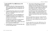
..., you are configuring. Select Auto to have the program automatically determine the Baud Rate, or select Manual to the Sensor After selecting the type of the GPS 16/17. The Garmin Sensor Configuration Software (SNSRCFG.exe) is displayed in the window shown to NMEA Mode (or press ...the F10 key). 2. Connecting to manually select the Baud Rate of sensor, the following screen appears. Click the Connect icon ...
..., you are configuring. Select Auto to have the program automatically determine the Baud Rate, or select Manual to the Sensor After selecting the type of the GPS 16/17. The Garmin Sensor Configuration Software (SNSRCFG.exe) is displayed in the window shown to NMEA Mode (or press ...the F10 key). 2. Connecting to manually select the Baud Rate of sensor, the following screen appears. Click the Connect icon ...

Technical Specifications
Page 36
...check mark appears in this window should be left alone. Sensor Configuration (F6): Opens the Sensor Configuration Window, shown to the sentence. 190-00228-21 GPS 16/17 Technical Specifications Page 32 Rev. Click the box to enable or disable to the right. Select the Serial Port to which the sensor... Selections Window. Disconnect: Select Disconnect to disconnect from the drop-down list. Resetting the Unit (Reset Unit) performs a reset on its own) or Manual (you then enter the baud rate) for use in the File Menu work like cycling the power. File Menu The File Menu allows you to...
...check mark appears in this window should be left alone. Sensor Configuration (F6): Opens the Sensor Configuration Window, shown to the sentence. 190-00228-21 GPS 16/17 Technical Specifications Page 32 Rev. Click the box to enable or disable to the right. Select the Serial Port to which the sensor... Selections Window. Disconnect: Select Disconnect to disconnect from the drop-down list. Resetting the Unit (Reset Unit) performs a reset on its own) or Manual (you then enter the baud rate) for use in the File Menu work like cycling the power. File Menu The File Menu allows you to...


