2006/2010/GPS 17 Installation
Page 2
... this manual must be returned to installation errors, abuse, misuse, accident, or unauthorized alteration or repairs. Except as the proof of purchase. The product should then be viewed and to change or improve its subsidiaries Garmin International, Inc. 1200 East 151st Street, Olathe, Kansas 66062, U.S.A. July 2005 2 Part Number 190-00228-01 Rev.F Printed in accordance with the tracking number clearly...
... this manual must be returned to installation errors, abuse, misuse, accident, or unauthorized alteration or repairs. Except as the proof of purchase. The product should then be viewed and to change or improve its subsidiaries Garmin International, Inc. 1200 East 151st Street, Olathe, Kansas 66062, U.S.A. July 2005 2 Part Number 190-00228-01 Rev.F Printed in accordance with the tracking number clearly...
2006/2010/GPS 17 Installation
Page 6
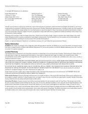
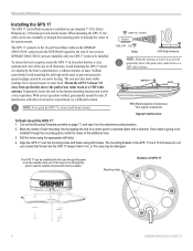
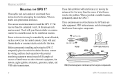
... a VHF radio antenna. If the coax is experienced, try a different location. INSTALLATION INSTRUCTIONS Installing the GPS 17 The GPS 17 can be flush mounted or installed on the mast to prevent inaccurate speed readings caused by excessive heeling. The mounting threads in the desired mounting location and test for the unit. EMI BETTER BEST GOOD SS JAYHAWK EMI (Electromagnetic Interference) from engine components Signal Interference...
... a VHF radio antenna. If the coax is experienced, try a different location. INSTALLATION INSTRUCTIONS Installing the GPS 17 The GPS 17 can be flush mounted or installed on the mast to prevent inaccurate speed readings caused by excessive heeling. The mounting threads in the desired mounting location and test for the unit. EMI BETTER BEST GOOD SS JAYHAWK EMI (Electromagnetic Interference) from engine components Signal Interference...

Installation Guide
Page 3
....nmea.org Radio Technical Commission For Maritime Services (RTCM) 1800 Diagonal Road, Suite 600, Alexandria, VA 22314-2480, USA Info line 703/684.4481 Fax. 703/836.4229 www.rtcm.org GPS 17 Installation Guide INTRODUCTION Introduction i Specifications 1 Mounting the Receiver 2 Mounting Location Tips 3 Routing the Cable 5 Wiring the GPS 17 6 Wire Color Code 6 Wiring Diagrams 7 Using the GPS 17 10 First Time Fix 10 Limited Warranty 11 This manual uses the term Warning...
....nmea.org Radio Technical Commission For Maritime Services (RTCM) 1800 Diagonal Road, Suite 600, Alexandria, VA 22314-2480, USA Info line 703/684.4481 Fax. 703/836.4229 www.rtcm.org GPS 17 Installation Guide INTRODUCTION Introduction i Specifications 1 Mounting the Receiver 2 Mounting Location Tips 3 Routing the Cable 5 Wiring the GPS 17 6 Wire Color Code 6 Wiring Diagrams 7 Using the GPS 17 10 First Time Fix 10 Limited Warranty 11 This manual uses the term Warning...

Installation Guide
Page 4
....garmin.com/prop65. ii The Global Positioning System (GPS) is operated by the United States government, which could result in an accident or collision resulting in conjunction with California's Proposition 65. The government's system is being provided in accordance with the GPS 17 only to facilitate, not to replace, the use the GPS 17 for aircraft navigation. GPS 17 Installation Guide When navigating, carefully compare information received...
....garmin.com/prop65. ii The Global Positioning System (GPS) is operated by the United States government, which could result in an accident or collision resulting in conjunction with California's Proposition 65. The government's system is being provided in accordance with the GPS 17 only to facilitate, not to replace, the use the GPS 17 for aircraft navigation. GPS 17 Installation Guide When navigating, carefully compare information received...

Installation Guide
Page 5
...). SPECIFICATIONS SPECIFICATIONS Physical Characteristics Size: 3.58" (91.0 mm) diameter, 3.60" (91.5 mm) high Weight: GPS 17 only: 7.1 oz (201 g) With 30 foot cable: 16.8 oz (465 g) With pole mount adapter & cable: 18.2 oz (516 grams) Pole mount adapter alone: 1.4 oz (40 grams) Cable alone: 9.7 oz (275 g) Cable: White PVC-jacketed, 30 foot, foil-shielded, 8-conductor 28 AWG with JST connector...
...). SPECIFICATIONS SPECIFICATIONS Physical Characteristics Size: 3.58" (91.0 mm) diameter, 3.60" (91.5 mm) high Weight: GPS 17 only: 7.1 oz (201 g) With 30 foot cable: 16.8 oz (465 g) With pole mount adapter & cable: 18.2 oz (516 grams) Pole mount adapter alone: 1.4 oz (40 grams) Cable alone: 9.7 oz (275 g) Cable: White PVC-jacketed, 30 foot, foil-shielded, 8-conductor 28 AWG with JST connector...
Installation Guide
Page 6
When in the desired location, connect the wiring, and then check operation with your Garmin dealer or a marine retailer for a suitable mount for the installation location. Check with potential interfering equipment turned on the control console. You can use an antenna mount to the receiver may be controlled by an on/off switch, such as a switch on and off. Examples of sources of interference for this item. If...
When in the desired location, connect the wiring, and then check operation with your Garmin dealer or a marine retailer for a suitable mount for the installation location. Check with potential interfering equipment turned on the control console. You can use an antenna mount to the receiver may be controlled by an on/off switch, such as a switch on and off. Examples of sources of interference for this item. If...
Installation Guide
Page 7
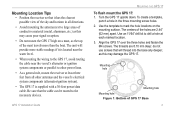
... poor signal reception. • Do not mount the GPS 17 high on the mounting surface. To create a template, punch a hole in all other antennas and the vessel's electrical system components (alternator/ignition system). • The GPS 17 is supplied with a 30-foot power/data cable. Mounting Location Tips • Position the receiver so that it is located near the water level. • When routing the wiring...
... poor signal reception. • Do not mount the GPS 17 high on the mounting surface. To create a template, punch a hole in all other antennas and the vessel's electrical system components (alternator/ignition system). • The GPS 17 is supplied with a 30-foot power/data cable. Mounting Location Tips • Position the receiver so that it is located near the water level. • When routing the wiring...

Installation Guide
Page 10
WIRING THE GPS 17 WIRING THE GPS 17 After mounting the GPS 17 in the desired location, connect the wiring. This ground connection acts as the (signal) Return line. You need a DB-9 or DB-25 serial connector (normally female) if you install a 1A fuse on the power (+) line of the receiving device. Check with a PC or electronics supplier for RTCM input only. Wire Color Code Red: Power (+) 8-40 VDC. Wire the unit to its own...
WIRING THE GPS 17 WIRING THE GPS 17 After mounting the GPS 17 in the desired location, connect the wiring. This ground connection acts as the (signal) Return line. You need a DB-9 or DB-25 serial connector (normally female) if you install a 1A fuse on the power (+) line of the receiving device. Check with a PC or electronics supplier for RTCM input only. Wire Color Code Red: Power (+) 8-40 VDC. Wire the unit to its own...
Installation Guide
Page 13
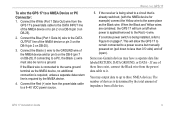
... DATA OUTPUT line of devices is already switched, (with the NMEA device for example) connect the Yellow wire to pin 2 on a DB-9 (pin 3 on DB-25). 3. You may have a separate data line labeled RETURN, DATA GROUND, or DATA -. If the receiver is being installed, refer to a NMEA Device or PC Connector: 1. Some non-Garmin devices may output data to up to a ground. The number of the NMEA device or pin 3 on the DB-9 (pin 2 on DB-25). 2. GPS 17 Installation Guide...
... DATA OUTPUT line of devices is already switched, (with the NMEA device for example) connect the Yellow wire to pin 2 on a DB-9 (pin 3 on DB-25). 3. You may have a separate data line labeled RETURN, DATA GROUND, or DATA -. If the receiver is being installed, refer to a NMEA Device or PC Connector: 1. Some non-Garmin devices may output data to up to a ground. The number of the NMEA device or pin 3 on the DB-9 (pin 2 on DB-25). 2. GPS 17 Installation Guide...
Installation Guide
Page 14
... SBAS systems use the same receiver frequency and are capable of Alaska. When turned on the Garmin Web site. Eventually, there will be given an opportunity to collect satellite data and determine its present position. USING THE GPS 17 USING THE GPS 17 First Time Fix The first time you turn on either coast, collect data from the factory in AutoLocate® mode, which allows the receiver to "fi...
... SBAS systems use the same receiver frequency and are capable of Alaska. When turned on the Garmin Web site. Eventually, there will be given an opportunity to collect satellite data and determine its present position. USING THE GPS 17 USING THE GPS 17 First Time Fix The first time you turn on either coast, collect data from the factory in AutoLocate® mode, which allows the receiver to "fi...
Installation Guide
Page 15
... replace the unit or software or offer a full refund of the purchase price at no charge to abuse, misuse, accident or unauthorized alteration or repairs. Tel. 913/397.8200 Fax. 913/397.8282 Garmin (Europe) Ltd. To obtain warranty service, an original or copy of the sales receipt from the date of purchase for shipping instructions and an RMA tracking number...
... replace the unit or software or offer a full refund of the purchase price at no charge to abuse, misuse, accident or unauthorized alteration or repairs. Tel. 913/397.8200 Fax. 913/397.8282 Garmin (Europe) Ltd. To obtain warranty service, an original or copy of the sales receipt from the date of purchase for shipping instructions and an RMA tracking number...
Technical Specifications
Page 4
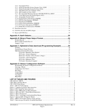
... Appendix D: Sensor Configuration Software 31 Downloading the Sensor Configuration Software 31 Selecting a Model...31 Connecting to the Sensor...31 File Menu ...32 Comm Menu...32 Config Menu ...32 View Menu...33 Help Menu...33 LIST OF TABLES AND FIGURES GPS 16LVS & 16HVS ...4 GPS17HVS with Pole Mount ...4 GPS 17HVS Flush Mount ...4 Table 1: GPS 16/17 Wire Pinout ...7 Figure 1: Computer Serial Port Interconnection...8 Figure 2: PDA Serial Port Interconnection...8 Figure 3: Basic NMEA Device Interconnection...8 Figure 4: GPS 16 & GPS 17 Flush Mount Dimensions 9 Figure 5: GPS 17 Dimensions...
... Appendix D: Sensor Configuration Software 31 Downloading the Sensor Configuration Software 31 Selecting a Model...31 Connecting to the Sensor...31 File Menu ...32 Comm Menu...32 Config Menu ...32 View Menu...33 Help Menu...33 LIST OF TABLES AND FIGURES GPS 16LVS & 16HVS ...4 GPS17HVS with Pole Mount ...4 GPS 17HVS Flush Mount ...4 Table 1: GPS 16/17 Wire Pinout ...7 Figure 1: Computer Serial Port Interconnection...8 Figure 2: PDA Serial Port Interconnection...8 Figure 3: Basic NMEA Device Interconnection...8 Figure 4: GPS 16 & GPS 17 Flush Mount Dimensions 9 Figure 5: GPS 17 Dimensions...
Technical Specifications
Page 7
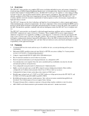
... position accuracy (see Section 1.7 Technical Specifications). • Compact, rugged design ideal for applications with software intelligence makes the GPS 16/17 easy to the prevailing weather conditions at most locations. • GPS 17HVS can be flush mounted or pole mounted on COM 1 port. • Flexible input voltage levels of high-performance aircraft. 1.4 Overview The GPS 16/17 series products are complete GPS sensors including embedded receiver and antenna, designed...
... position accuracy (see Section 1.7 Technical Specifications). • Compact, rugged design ideal for applications with software intelligence makes the GPS 16/17 easy to the prevailing weather conditions at most locations. • GPS 17HVS can be flush mounted or pole mounted on COM 1 port. • Flexible input voltage levels of high-performance aircraft. 1.4 Overview The GPS 16/17 series products are complete GPS sensors including embedded receiver and antenna, designed...
Technical Specifications
Page 10
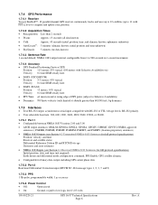
... position, time, and almanac known; ephemeris unknown) • AutoLocate®: 5 minutes (almanac known; initial position and time unknown) • SkySearch: 5 minutes (no data known) 1.7.4.3 Sentence Rate 1 second default; 1.7.4 GPS Performance 1.7.4.1 Receiver WAAS Enabled™; 12 parallel channel GPS receiver continuously tracks and uses up to 12 satellites (up to 11 with PPS active) to 900 seconds in 1-second increments 1.7.4.4 Accuracy • GPS Standard Positioning Service (SPS) Position...
... position, time, and almanac known; ephemeris unknown) • AutoLocate®: 5 minutes (almanac known; initial position and time unknown) • SkySearch: 5 minutes (no data known) 1.7.4.3 Sentence Rate 1 second default; 1.7.4 GPS Performance 1.7.4.1 Receiver WAAS Enabled™; 12 parallel channel GPS receiver continuously tracks and uses up to 12 satellites (up to 11 with PPS active) to 900 seconds in 1-second increments 1.7.4.4 Accuracy • GPS Standard Positioning Service (SPS) Position...
Technical Specifications
Page 11
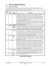
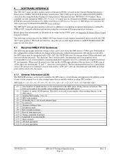
... Technical Specifications Page 7 Rev. A 2 GPS 16/17 WIRING AND PINOUTS 2.1 GPS 16/17 Pinout The GPS 16LVS and GPS 16HVS sensors utilize an 8-pin RJ-45 plug. The GPS 17HVS terminates in the range of 300 to heat rapidly and eventually power the unit off and drops the supply current to receive serial differential GPS data formatted per NMEA 0183, Version 3.0. Typical operating power is 2.4 V. Power and Signal Ground External Power Control Input. Pulling this pin to PORT 1 DATA OUT. First Serial...
... Technical Specifications Page 7 Rev. A 2 GPS 16/17 WIRING AND PINOUTS 2.1 GPS 16/17 Pinout The GPS 16LVS and GPS 16HVS sensors utilize an 8-pin RJ-45 plug. The GPS 17HVS terminates in the range of 300 to heat rapidly and eventually power the unit off and drops the supply current to receive serial differential GPS data formatted per NMEA 0183, Version 3.0. Typical operating power is 2.4 V. Power and Signal Ground External Power Control Input. Pulling this pin to PORT 1 DATA OUT. First Serial...
Technical Specifications
Page 16
Binary phase data information can be received on the GPS sensors' COM 1 port. Null fields in the configuration sentence indicate no change in the unlikely event of non-volatile memory loss or after any number when sending almanac to the GPS sensor. It is based on the National Marine Electronics Association's NMEA 0183 ASCII interface specification. Number of each almanac page Eccentricity Almanac reference time Inclination angle Rate of...
Binary phase data information can be received on the GPS sensors' COM 1 port. Null fields in the configuration sentence indicate no change in the unlikely event of non-volatile memory loss or after any number when sending almanac to the GPS sensor. It is based on the National Marine Electronics Association's NMEA 0183 ASCII interface specification. Number of each almanac page Eccentricity Almanac reference time Inclination angle Rate of...

Technical Specifications
Page 17
... retained between power cycles. Refer to the GPS sensor. $PGRMC,,,,,,,,,,,,,,*hh Fix mode, A = automatic, 2 = 2D exclusively (host system must be obtained by sending $PGRMCE to Appendix A: Earth Datums for satellite acquisition. Configuration parameters are detected. Current default values can also be transmitted) Longitude hemisphere, E or W Current UTC date, ddmmyy format Current UTC time, hhmmss format Receiver Command, A = Auto Locate, R = Unit Reset 4.1.3 Sensor Configuration Information (PGRMC) The $PGRMC sentence provides information used for...
... retained between power cycles. Refer to the GPS sensor. $PGRMC,,,,,,,,,,,,,,*hh Fix mode, A = automatic, 2 = 2D exclusively (host system must be obtained by sending $PGRMCE to Appendix A: Earth Datums for satellite acquisition. Configuration parameters are detected. Current default values can also be transmitted) Longitude hemisphere, E or W Current UTC date, ddmmyy format Current UTC time, hhmmss format Receiver Command, A = Auto Locate, R = Unit Reset 4.1.3 Sensor Configuration Information (PGRMC) The $PGRMC sentence provides information used for...

Technical Specifications
Page 18
... 0.0) at the factory: GPGGA, GPGSA, GPGSV, GPRMC, and PGRMT. 4.1.4 Additional Sensor Configuration Information (PGRMC1) The $PGRMC1 sentence provides additional information used to enable and disable specific output sentences. Configuration parameters are not filtered (or masked to the GPS sensor. $PGRMC1,,,,,,,,,,,,,,*hh NMEA 0183 output time 1-900 (sec) Binary Phase Output Data, 1 = Off, 2 = On. If an error is '0' (disable) or '1' (enable), the target sentence description field must enable Garmin Data Transfer format to...
... 0.0) at the factory: GPGGA, GPGSA, GPGSV, GPRMC, and PGRMT. 4.1.4 Additional Sensor Configuration Information (PGRMC1) The $PGRMC1 sentence provides additional information used to enable and disable specific output sentences. Configuration parameters are not filtered (or masked to the GPS sensor. $PGRMC1,,,,,,,,,,,,,,*hh NMEA 0183 output time 1-900 (sec) Binary Phase Output Data, 1 = Off, 2 = On. If an error is '0' (disable) or '1' (enable), the target sentence description field must enable Garmin Data Transfer format to...

Technical Specifications
Page 35
... Serial Port to NMEA Mode (or press the F10 key). 2. Refer to this section when using the software to configure your sensor, you are configuring. Selecting a Model After opening the program (snsrcfg.exe), the following window opens. Select Config > Switch to which the sensor is displayed in the window shown to open the Comm Setup Window. 3. To view the current programming of Garmin sensor you must first connect...
... Serial Port to NMEA Mode (or press the F10 key). 2. Refer to this section when using the software to configure your sensor, you are configuring. Selecting a Model After opening the program (snsrcfg.exe), the following window opens. Select Config > Switch to which the sensor is displayed in the window shown to open the Comm Setup Window. 3. To view the current programming of Garmin sensor you must first connect...

Technical Specifications
Page 36
... GPS 16/17 Technical Specifications Page 32 Rev. This is enabled, a check mark appears in the File Menu work like cycling the power. The items in the box to open, save, and print sensor configurations. Click the box to enable or disable to change or view the configuration. Config Menu The Config (Configuration) Menu allows you to the left of the data from the drop-down list. Resetting...
... GPS 16/17 Technical Specifications Page 32 Rev. This is enabled, a check mark appears in the File Menu work like cycling the power. The items in the box to open, save, and print sensor configurations. Click the box to enable or disable to change or view the configuration. Config Menu The Config (Configuration) Menu allows you to the left of the data from the drop-down list. Resetting...


