Owner's Manual
Page 8
... Interface Cable • MapSource Points of Interest CD-ROM • Beacon Receiver for differential corrections: GBR21 (E-Field Antenna), or GBR23 (H-Field Antenna) • Internal Antenna, Bail Mount (International model only) • 2nd Mounting Station Introduction Packing List vi Before installing and getting started with package containing the internal antenna. Standard Package: • GPS 152...
... Interface Cable • MapSource Points of Interest CD-ROM • Beacon Receiver for differential corrections: GBR21 (E-Field Antenna), or GBR23 (H-Field Antenna) • Internal Antenna, Bail Mount (International model only) • 2nd Mounting Station Introduction Packing List vi Before installing and getting started with package containing the internal antenna. Standard Package: • GPS 152...

Owner's Manual
Page 45
Use the ARROW KEYPAD to a computer using an optional PC cable and interface software or write them down manually. deletes waypoints that use the same symbol. • Delete All - It is advisable to back up important ...
Use the ARROW KEYPAD to a computer using an optional PC cable and interface software or write them down manually. deletes waypoints that use the same symbol. • Delete All - It is advisable to back up important ...
Owner's Manual
Page 90
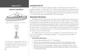
... available at most marine dealers. If you may skip this section and proceed to lock the cable into place. Use the appropriate tie-wraps, fasteners and sealant to secure the cable along the route and through or outside the antenna mount. Once the GPS 152 unit has been ... The GARMIN antenna screws directly onto any standard 1" x 14-thread antenna mount. To complete the installation, you turn the antenna cable connector 1/4 turn clockwise to the next page. Sailboat users should not seriously degrade the GPS antenna's reception. Route the cable to route the coaxial cable either ...
... available at most marine dealers. If you may skip this section and proceed to lock the cable into place. Use the appropriate tie-wraps, fasteners and sealant to secure the cable along the route and through or outside the antenna mount. Once the GPS 152 unit has been ... The GARMIN antenna screws directly onto any standard 1" x 14-thread antenna mount. To complete the installation, you turn the antenna cable connector 1/4 turn clockwise to the next page. Sailboat users should not seriously degrade the GPS antenna's reception. Route the cable to route the coaxial cable either ...
Owner's Manual
Page 91
... (in storage or operating conditions) may be blocked by the boat's superstructure, a radar arch, or mast. , The temperature range for the GPS 152 is designed for mounting in exposed locations or at least a 3" (5 cm) clearance behind the case to allow connection of the antenna (external ... G Unit Installation 81 Connect the power/data and antenna cables (external antenna only) to the back of the sky in internal bail mount antenna, it will be surface mounted or flush mounted. Mounting the GPS 152 Unit The GPS 152's compact, waterproof case is suitable for a tight fi...
... (in storage or operating conditions) may be blocked by the boat's superstructure, a radar arch, or mast. , The temperature range for the GPS 152 is designed for mounting in exposed locations or at least a 3" (5 cm) clearance behind the case to allow connection of the antenna (external ... G Unit Installation 81 Connect the power/data and antenna cables (external antenna only) to the back of the sky in internal bail mount antenna, it will be surface mounted or flush mounted. Mounting the GPS 152 Unit The GPS 152's compact, waterproof case is suitable for a tight fi...
Owner's Manual
Page 92
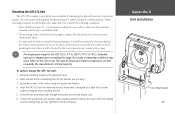
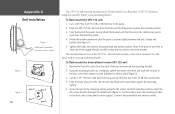
... International version of the panel for more support. From the front, place the GPS 152 into the hole from the back of .08-.52" thickness using the M5 screws. Connect the power/data and antenna cables. Using the mounting bracket as a template, outline the center relief hole and mark... mm) screw holes. 4. Tighten the knobs and connect the power/data and antenna cables. Note: if the panel is pinched tightly between the unit's flange and bracket lobe (figure 1). 5. Place the GPS 152 into the relief hole until cam lobe contacts surface. From the back of the panel...
... International version of the panel for more support. From the front, place the GPS 152 into the hole from the back of .08-.52" thickness using the M5 screws. Connect the power/data and antenna cables. Using the mounting bracket as a template, outline the center relief hole and mark... mm) screw holes. 4. Tighten the knobs and connect the power/data and antenna cables. Note: if the panel is pinched tightly between the unit's flange and bracket lobe (figure 1). 5. Place the GPS 152 into the relief hole until cam lobe contacts surface. From the back of the panel...
Owner's Manual
Page 93
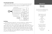
... copy of GARMIN's proprietary communication protocol the Help and Support section of external devices: GARMIN proprietary Differential GPS (DGPS), NMEA 0183 (version 2.3), RTCM SC-104 input (version 2.0). Connecting the Power/Data The power/data cable connects the GPS 152 to NMEA In.../NMEA Out. The following formats are the sentences for NMEA 0183, version 2.3 output: Approved sentences - GPBOD, GPBWC, GPGGA, GPGLL, GPGSA, GPGSV, GPRMB, GPRMC, GPRTE, GPVTG, GPWPL, and GPXTE; PGRME, PGRMM, PGRMZ, and PSLIB. Brown GBR 23 Beacon Blue Receiver...
... copy of GARMIN's proprietary communication protocol the Help and Support section of external devices: GARMIN proprietary Differential GPS (DGPS), NMEA 0183 (version 2.3), RTCM SC-104 input (version 2.0). Connecting the Power/Data The power/data cable connects the GPS 152 to NMEA In.../NMEA Out. The following formats are the sentences for NMEA 0183, version 2.3 output: Approved sentences - GPBOD, GPBWC, GPGGA, GPGLL, GPGSA, GPGSV, GPRMB, GPRMC, GPRTE, GPVTG, GPWPL, and GPXTE; PGRME, PGRMM, PGRMZ, and PSLIB. Brown GBR 23 Beacon Blue Receiver...


