Product Manual
Page 12
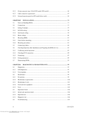
4.3.2 4.3.3 4.3.4 68-pin connector type 16-bit SCSI model (NP model 60 Cable connector requirements 67 External operator panel (on NP model drives only 68 CHAPTER 5 INSTALLATION 71 5.1 Notes on Handling HDDs 71 5.2 Connections...73 5.3 Setting Terminals ...75 5.3.1 SCSI ID setting...76 5.3.2 Each mode setting ...78 5.3.3 Mode settings ...80 5.4 Mounting HDDs...81 5.4.1 Check before mounting ...81...
4.3.2 4.3.3 4.3.4 68-pin connector type 16-bit SCSI model (NP model 60 Cable connector requirements 67 External operator panel (on NP model drives only 68 CHAPTER 5 INSTALLATION 71 5.1 Notes on Handling HDDs 71 5.2 Connections...73 5.3 Setting Terminals ...75 5.3.1 SCSI ID setting...76 5.3.2 Each mode setting ...78 5.3.3 Mode settings ...80 5.4 Mounting HDDs...81 5.4.1 Check before mounting ...81...
Product Manual
Page 16
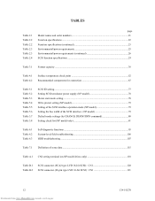
...interface operation mode (NP model 79 Setting the bus width of the SCSI interface (NP model 79 Default mode settings (by CHANGE DEFINITION command 80 Setting check list (NP model only 81 Table 6.1 Table 6.2 Table 6.3 Self-diagnostic functions ...95 System-level field troubleshooting 106 HDD troubleshooting ... 7.1 Definition of sense data ...115 Table A.1 CN2 setting terminal (on NP model drives only 118 Table B.1 Table B.2 SCSI connector (SCA2 type LVD 16-bit SCSI): CN1 120 SCSI connector (68-pin type LVD 16-bit SCSI): CN1 121 12 Downloaded from www.Manualslib.com manuals search...
...interface operation mode (NP model 79 Setting the bus width of the SCSI interface (NP model 79 Default mode settings (by CHANGE DEFINITION command 80 Setting check list (NP model only 81 Table 6.1 Table 6.2 Table 6.3 Self-diagnostic functions ...95 System-level field troubleshooting 106 HDD troubleshooting ... 7.1 Definition of sense data ...115 Table A.1 CN2 setting terminal (on NP model drives only 118 Table B.1 Table B.2 SCSI connector (SCA2 type LVD 16-bit SCSI): CN1 120 SCSI connector (68-pin type LVD 16-bit SCSI): CN1 121 12 Downloaded from www.Manualslib.com manuals search...
Product Manual
Page 33
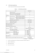
... × Differential type Position where the terminating resistor is mounted on the PCA × TERMPWR signal send function Ο (NP model) Connector 68-pin P cable connector 80-pin SCA2 connector Ο (NP model) Ο (NC model) Data bus parity (Data bus CRC) Ο Bus arbitration function Ο Disconnection... Refer to #15 (Jumper selection, NP model) #0 fixed Ο 20 MB/s max. Ο 40 MB/s max. Ο 40 MB/s max. Ο 80 MB/s max. Ο 160 MB/s max. Ο 320 MB/s max. 2.2 SCSI Function Specifications Table 2.4 shows the SCSI functions provided with the HDD.
... × Differential type Position where the terminating resistor is mounted on the PCA × TERMPWR signal send function Ο (NP model) Connector 68-pin P cable connector 80-pin SCA2 connector Ο (NP model) Ο (NC model) Data bus parity (Data bus CRC) Ο Bus arbitration function Ο Disconnection... Refer to #15 (Jumper selection, NP model) #0 fixed Ο 20 MB/s max. Ο 40 MB/s max. Ο 40 MB/s max. Ο 80 MB/s max. Ο 160 MB/s max. Ο 320 MB/s max. 2.2 SCSI Function Specifications Table 2.4 shows the SCSI functions provided with the HDD.

Product Manual
Page 81
... Short Open Short Open Short Open Short Open Short Open Short NC model (CN1) Pin 79 Pin 40 Open Open Short Short Open Open Short Short Open Open Short Short Open Open Short... Short Short Open Open Open Open Short Short Short Short Pin 80 Open Open Open Open Open Open Open Open Short Short Short Short Short Short Short Short Pin pair 1/2 Open Short Open Short Open Short Open Short ...Open Short Open Short Open Short Open Short NP model (CN2) Pin pair Pin pair Pin pair 3/4 5/6 7/8 Open Open Open Open Open Open Short Open Open Short Open Open Open Short...
... Short Open Short Open Short Open Short Open Short Open Short NC model (CN1) Pin 79 Pin 40 Open Open Short Short Open Open Short Short Open Open Short Short Open Open Short... Short Short Open Open Open Open Short Short Short Short Pin 80 Open Open Open Open Open Open Open Open Short Short Short Short Short Short Short Short Pin pair 1/2 Open Short Open Short Open Short Open Short ...Open Short Open Short Open Short Open Short NP model (CN2) Pin pair Pin pair Pin pair 3/4 5/6 7/8 Open Open Open Open Open Open Short Open Open Short Open Open Open Short...

Product Manual
Page 124
B.1 SCSI Connector Signal Allocation: SCA2 type LVD 16-bit SCSI Pin No. 01 02 03 04 05 06 07 08 09 10 11 12 13 14 15 16 17 18 19 20 21 22 23 24 ... DB03 DB02 DB01 DB00 DBP1 DB15 DB14 DB13 DB12 5V RETURN (MATED 2) 5V RETURN (GND) 5V RETURN (GND) -LED DLYD START SCSI ID1 SCSI ID3 Pin No. 41 42 43 44 45 46 47 48 49 50 51 52 53 54 55 56 57 58 59 60 61 62 63 64... 65 66 67 68 69 70 71 72 73 74 75 76 77 78 79 80 120 Downloaded from www.Manualslib.com manuals search engine C141-E270 RMT START SCSI ID0 SCSI ID2 Signal 12V RETURN (GND) 12V...
B.1 SCSI Connector Signal Allocation: SCA2 type LVD 16-bit SCSI Pin No. 01 02 03 04 05 06 07 08 09 10 11 12 13 14 15 16 17 18 19 20 21 22 23 24 ... DB03 DB02 DB01 DB00 DBP1 DB15 DB14 DB13 DB12 5V RETURN (MATED 2) 5V RETURN (GND) 5V RETURN (GND) -LED DLYD START SCSI ID1 SCSI ID3 Pin No. 41 42 43 44 45 46 47 48 49 50 51 52 53 54 55 56 57 58 59 60 61 62 63 64... 65 66 67 68 69 70 71 72 73 74 75 76 77 78 79 80 120 Downloaded from www.Manualslib.com manuals search engine C141-E270 RMT START SCSI ID0 SCSI ID2 Signal 12V RETURN (GND) 12V...

